
Related Manuals for Kitronik 2136


Summary of Contents for Kitronik 2136
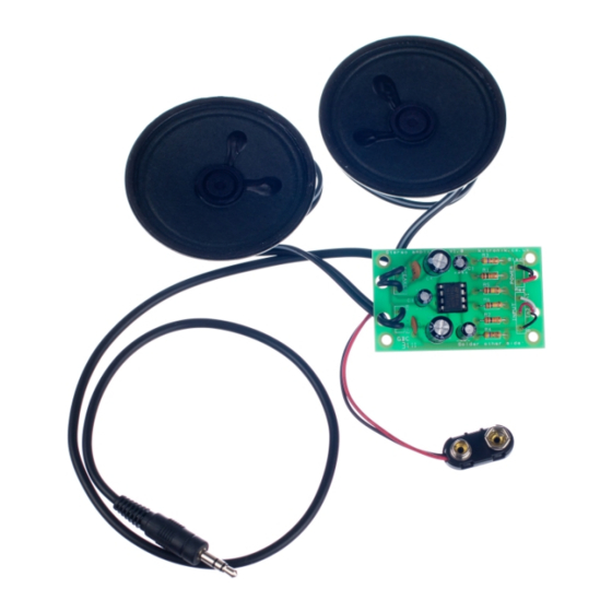
- Page 1 ESSENTIAL INFORMATION BUILD INSTRUCTIONS CHECKING YOUR PCB & FAULT-FINDING MECHANICAL DETAILS HOW THE KIT WORKS CREATE YOUR OWN SPEAKER DOCK WITH THIS STEREO AMPLIFIER KIT Version 2.0...
-
Page 2: Build Instructions
Stereo Amplifier Essentials www.kitronik.co.uk/2136 Build Instructions Before you start, take a look at the Printed Circuit Board (PCB). The components go in the side with the writing on and the solder goes on the side with the tracks and silver pads. -
Page 3: Checking Your Amplifier Pcb
Stereo Amplifier Essentials www.kitronik.co.uk/2136 ATTACH THE BATTERY CLIP The PP3 battery clip should be attached to the terminals labelled ‘POWER’. Connect the red wire to ‘+’ and the black wire to ‘-’ after feeding it through the strain relief hole. -
Page 4: Adding An On / Off Switch
Stereo Amplifier Essentials www.kitronik.co.uk/2136 Adding an On / Off Switch If you wish to add a power switch, don’t solder both ends of the battery clip directly into the board, instead: Solder one end of the battery clip to the PCB, either black to ‘-‘ or red to ‘+’. -
Page 5: Fault Finding
Stereo Amplifier Essentials www.kitronik.co.uk/2136 Fault finding flow chart Start Fault Finding Power up the board with it connected to a music source Check IC1 is in the right way around For dry joints on the power connectors The input connector is in the... -
Page 6: Designing The Enclosure
Stereo Amplifier Essentials www.kitronik.co.uk/2136 Designing the Enclosure When you design the enclosure, you will need to consider: The size of the PCB (below left, height including components = 15mm). How big the batteries are. How to mount the two speakers (below right). -
Page 7: How The Amplifier Works
Stereo Amplifier Essentials www.kitronik.co.uk/2136 How the Amplifier Works TDA2822 Input 100K 470 F Speaker 1 In 1 + Out 1 In 1 - Battery In 2 + (15V max) 100K Out 2 In 2 - 470 F Speaker 2 10 F... -
Page 8: Online Information
/ omissions in the notes. Kitronik Ltd - Any unauthorised copying / duplication of this booklet or part thereof for purposes except for use with Kitronik project kits is not allowed without Kitronik’s prior consent.
Need help?
Do you have a question about the 2136 and is the answer not in the manual?
Questions and answers