Advertisement
Table of Contents
- 1 Unpacking the Equipment
- 2 Installing the BUC Equipment
- 3 Power Supply Units
- 4 DC-Powered Bucs
- 5 Pin Description
- 6 AC-Powered Bucs
- 7 Cable Installation
- 8 General Guidelines
- 9 Securing Cables
- 10 Sealing the Connectors
- 11 Typical BUC System Configurations
- 12 Essential Risk Management for Safeguarding Personnel, Protecting Equipment, and Dissipating Lightning
- 13 Mounting Kits
- 14 Flange Kits
- 15 Sealing Kits
- Download this manual
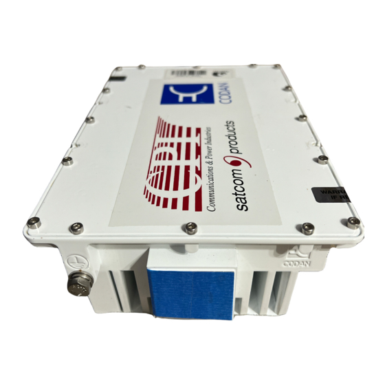
Ku-Band BUC systems
Overview
Codan provides a range of BUCs of varying power ranges that operate in basic
single-BUC systems or redundancy systems. These BUCs operate in the
C-Band and Ku-Band frequency ranges. For information on the C-Band and
Ku-Band ranges of products see Application Notes 17-60114 and 17-60115
respectively.
These installation instructions describe cabling and mechanical fitting
guidelines. They are applicable to single-stream Ku-Band BUC installations.
These instructions provide the following information:
•
general installation requirements
•
a complete list of the contents of each kit
•
mounting drawings with instructions
For technical setup and operating information, see specific Application Notes
on the Codan web site or the Satcom Technical Information CD.
© 12-50176-EN Issue 2, December 2010
Head office
Codan Limited
ABN 77 007 590 605
81 Graves Street
Newton SA 5074
AUSTRALIA
Telephone
+61 8 8305 0311
Facsimile
+61 8 8305 0411
www.codan.com.au
Asia Pacific
Codan Limited
81 Graves Street
Newton SA 5074
AUSTRALIA
Telephone
+61 8 8305 0427
Facsimile
+61 8 8305 0410
asiatech.support@codan.com.au
4916L-W/E-DC/EX-CE-NI
4908L-W/E-DC/EX-CE-NI
4916-W/E-DC/EX-CE-NI
4908-W/E-DC/EX-CE-NI
4916-MINIBUC
4908-MINIBUC
EMEA
Codan (UK) Ltd
Unit C4 Endeavour Place
Coxbridge Business Park
Farnham Surrey GU10 5EH
UNITED KINGDOM
Telephone
+44 1252 717 272
Facsimile
+44 1252 717 337
uktech.support@codan.com.au
Page 1 of 18
Americas
Codan Satcom
(Locus Microwave, Inc.)
176 Technology Drive, Suite 200
Boalsburg PA 16827
USA
Telephone
+1 814 777 4762
Facsimile
+1 814 466 1104
ustech.support@codan.com.au
Advertisement
Table of Contents

Related Manuals for Codan 4916L-W/E-DC/EX-CE-NI

Summary of Contents for Codan 4916L-W/E-DC/EX-CE-NI
- Page 1 Ku-Band BUC systems 4908-MINIBUC Overview Codan provides a range of BUCs of varying power ranges that operate in basic single-BUC systems or redundancy systems. These BUCs operate in the C-Band and Ku-Band frequency ranges. For information on the C-Band and Ku-Band ranges of products see Application Notes 17-60114 and 17-60115 respectively.
-
Page 2: Unpacking The Equipment
If anything is missing or damaged, please contact your nearest Codan office immediately to obtain the correct warranty service procedures. This ensures prompt assistance, minimal turnaround time, and avoids any freight issues. - Page 3 Ku-Band BUC systems Figure 1: Installation flow chart Install power to the site. Install antenna as per manufacturer’s instructions. Install any other mounting structures. See instructions provided with mounting kits and Install BUC system page 4, General guidelines for installing single- as per mounting instructions.
- Page 4 LNB. BUCs are supplied with W/G outputs and an optional pole or universal boom mounting kit suitable for the Codan range of L/M/RBUCs. Contact your antenna manufacturer if you have specific installation requirements. It is recommended that BUCs are installed as close as possible to the antenna feed to minimise losses.
-
Page 5: Power Supply Units
Ku-Band BUC systems M&C For more information on the M&C interfaces see Application Note: M&C NOTE interface diagrams of the BUC and 7586L Controller, 17-60132. For remote monitor and control of the ODU, you can use a 6570 Remote Controller, or a computer connected to the serial interface or the LAN interface (RBUCs only). -
Page 6: Dc-Powered Bucs
Ku-Band BUC systems DC-powered BUCs The BUCs can be DC-powered from: • an L-Band modem or an appropriate PSU via the IF cable to the IF INPUT connector on the BUC (up to 16 W) • an appropriate PSU via a separate DC power cable to the DC INPUT connector on the BUC (BUCs with external power connector only) Before applying power to the BUC, ensure that the installation complies WARNING... -
Page 7: Ac-Powered Bucs
Ku-Band BUC systems AC-powered BUCs AC-powered BUCs operate with an AC input voltage in the range 115 to 240 V AC. Check BUC specifications for the exact voltage range of your BUC. WARNING Voltages outside of these limits may cause damage to the BUC. If you need to make your own AC mains cable, or re-terminate the cable supplied, Table 2 lists the pin connections and describes the input functions available on the... -
Page 8: Cable Installation
Where required, you must use standard shielded Codan cables for the power and control cabling to ensure safety and EMI/EMC standards are met. In installations where the cables are not supplied by Codan, all power and control cables must be assembled in accordance with drawings supplied by Codan. -
Page 9: Sealing The Connectors
Ku-Band BUC systems Sealing the connectors After the equipment has been set up and tested to your requirements, seal all connections of the BUC and antenna feed according to Application Note: Sealing N-type and MS connectors in satellite equipment installations, 17-60094 (provided in Kit, Connector Sealing (15-40202)), and Application Note: Sealing waveguide connections, 17-60128. -
Page 10: Typical Buc System Configurations
Ku-Band BUC systems Typical BUC system configurations Figure 2: BUC with L-Band modem and LNB External AC power connector or +48 V DC power L-Band Tx IF, +24/48 V DC power (DC-powered BUC only), Tx to 10 MHz Ref, FSK M&C antenna M&C RS232/422/485... - Page 11 Ku-Band BUC systems Figure 3: BUC with L-Band modem, external in-line PSU, and LNB L-Band Tx IF, 48 V DC, Tx to 10 MHz Ref, FSK M&C antenna External AC mains in-line BUC PSU RS232/422/485 LAN M&C M&C (RBUC only) M&C L-Band Tx IF, 10 MHz Ref,...
-
Page 12: Essential Risk Management For Safeguarding Personnel, Protecting Equipment, And Dissipating Lightning
Ku-Band BUC systems Essential risk management for safeguarding personnel, protecting equipment, and dissipating lightning Precautions must be taken to ensure the installation is adequately WARNING protected against voltage potential differences that may occur between the outdoor and indoor equipment. These potential differences may occur: •... -
Page 13: Mounting Kits
Ku-Band BUC systems Kits Mounting kits Table 3: Kit, Boom Mounting, Universal to 100 W (15-42072-000) Description Component part number Channel, Mounting (qty 2) 05-06876 Rod, Threaded M8 × 250 mm (qty 4) 05-06904 Bracket, Mounting (qty 2) 05-07272 Spacer (qty 8) 05-07273 Rod, Threaded M8 ×... - Page 14 Ku-Band BUC systems Table 5: Kit, Mounting, 8” Pole, PSU (15-40128) Description Component part number Rod, Threaded, M8 × 250 mm (qty 4) 05-06904 Bracket, Mounting (qty 4) 05-07532 Fitting Instruction, PSU/Controller 15-40128-001 Nut, M8, Stainless steel, Hex (qty 18) 32-00800-080 Washer, M8, Stainless steel, Flat (qty 22) 32-00801-080...
-
Page 15: Flange Kits
Ku-Band BUC systems Flange kits Table 7: Kit, Flange, WR75, Thick groove (15-40172) Description Component part number Nut, M4, Stainless steel, Hex (qty 5) 31-24000-080 Washer, M4, Stainless steel, Normal (qty 10) 31-24001-080 Washer, M4, Stainless steel, Spring (qty 5) 31-24001-580 Screw, M4 ×... -
Page 16: Sealing Kits
Ku-Band BUC systems Sealing kits Table 9: Kit, Connector Sealing (15-40202) Description Component part number Application Note, Sealing N-type and MS connectors in 17-60094 satellite equipment installations Tape, Vinyl Elec 19 mm × 6 m 30-39301-007 Tape, Self-amalgamating 19 mm, Wide 30-39304-002 Page 16 of 18 12-50176-EN Issue 2, December 2010... - Page 17 Drawings Use these drawings as a guideline for installing your products. Table 10: Mounting drawings Title Codan part number Boom Mounting, Universal to 100 W (BUC) 15-42072-001 (sheet 1) Boom Mounting, Universal (7580 PSU) 15-42072-001 (sheet 2) Pole Mounting, 8" to 12", RBUC, C/Ku 15-42098-001 PSU/5586 8"...
- Page 18 Ku-Band BUC systems This page has been left blank intentionally. Page 18 of 18 12-50176-EN Issue 2, December 2010...
- Page 19 15-42072-001 (sheet 1)
- Page 20 15-42072-001 (sheet 2)
- Page 21 15-42098-001...
- Page 22 15-40128-001...
- Page 23 15-40147-001...
- Page 24 01-01192...
- Page 25 01-01828...
- Page 26 01-01302...
- Page 27 01-01689...
- Page 28 01-01785...
Need help?
Do you have a question about the 4916L-W/E-DC/EX-CE-NI and is the answer not in the manual?
Questions and answers