Table of Contents
Advertisement
Advertisement
Table of Contents

Related Manuals for WELDPRO TIGACDC200GD


Summary of Contents for WELDPRO TIGACDC200GD
- Page 1 TIGACDC200GD LINLONG LIMITED Operator’s Manual www.weldpro.com...
- Page 2 Introduction Thank you for purchasing the Weldpro TIGACDC200GD welder. This welder is designed and built using the very best quality components to afford a great welding experience and great performance. This manual contains the description of the hardware and the operating instructions of the equipment. For your safety and that of others, please read this manual carefully.
-
Page 3: Table Of Contents
CONTENTS 1 SAFETY WARNING........................ 2 PRODUCT DESCRIPTION....................... 3 TWO YEAR WARRANTY......................4 TECHNICAL PARAMETERS....................GENERAL WELDING FACTS ....................ELECTRICAL VOLTAGE ......................INSTALLATION ........................OPERATION .......................... TROUBLESHOOTING ...................... -
Page 4: Safety Warning
SAFETY WARNING The safety notes contained in this manual are to ensure the correct use of the machinery and to prevent injury to the user or other persons. The welding machine was designed and manufactured with safety in mind. Please refer to the safety warning contained in the manual to avoid accidents. - Page 5 DANGER Please observe the following rules to avoid serious accidents • Never use the equipment for purposes other than welding. • Follow related regulations regarding the characteristics of the power source, choice of place, usage of high- pressure gas, storage, configuration, safe-keeping of the workpiece after welding and disposal of waste, etc. •...
- Page 6 WARNING The gases and fumes are hazardous to health, please wear personal protective equipment according to regulations • Wear exhaust equipment and respiratory protective equipment to prevent gas poisoning or choke. • Use suggested exhaust ventilation system and respiratory protective equipment to prevent injuries or poisoning by gas or dust.
- Page 7 ATTENTION For better work efficiency and power source maintenance, please note the following: • Take precautions to prevent toppling. • Never use welding equipment to unfreeze a pipe. • Lift the power source from side when using a forklift to avoid toppling. •...
-
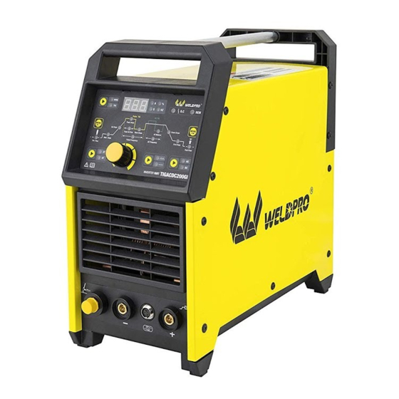
Page 8: Product Description
This is no longer a concern with the Weldpro ACDCTIG200 since all amperage control settings are made from the console on the machines face. -
Page 9: Two Year Warranty
Weldpro will not be responsible in the event of a product failure, for lost time in operation or use of said product. Rather it will honor solely the product itself only. -
Page 10: Technical Parameters
TECHNICAL PARAMETERS Model TIGACDC200GD Parameters Supply voltage (V) 115V±15% 230V±15% Frequency (Hz) TIG: 26.4 TIG: 26.8 Rated input current (A) MMA: 44.3 MMA: 36.5 No-load voltage (V) TIG: 120 TIG: 200 Output current (A) MMA: 120 MMA: 180 TIG: 14.8... - Page 11 INSTALLATION Component setup of this welding machine is a simple, straight forward process. This welder is fitted with a Power Voltage Compensator that takes into consideration a + / - 15% of the rated voltage for this machine. However it is most important to be sure your power supply to this welding is of the proper voltage and is in good condition with clean connections, proper wiring and the correct circuit breakers.
- Page 12 Simply put, the 2T function require 2 Trigger button movements to start and end a weld. 1 push to start the weld, and 2 release to end the weld. The 4T function requires 4 Trigger button movements to start and end a weld. 1 push to start the weld, 2 release to maintain the weld and continue, 3 push the trigger button once again as the first step to ending the weld, and finally 4, release the button to stop the weld.
-
Page 13: Installation
• Installation diagram • Blow is setup for MMA Stick welding This is NEGATIVE ground clamp here This is the PLUS connector Electrode holder goes here not ground clamp... -
Page 14: Operation
Along the middle / center row of functions you will find a selection of all the advanced features of the TIGACDC200GD machine. At each end of the center row you will find a menu button. Depending on how far along the line of options you are, you can click either menu button to proceed left to right or right to left. - Page 15 The TIGACDC200GD welder has a very adjustable Pulse feature which can be adjusted multiple ways to offer an almost infinite range of variables. Pulse is just as it implies, a pulsing of amperage power while welding. Pulse Frequency is the number of times per second amperage pulses will occur. The range is 0.5 to 200 HZ, or times per second.
- Page 16 Below is an illustrated explanation of the functions 1 Panel Layout Digital Display Meter Abnormal Indicator Light Remote Control Indicator Light STICK/TIG Selector Button Move Right Selector Menu Button Move Left Selector Menu Button 2T/4T Selector Button AC/DC Selector Button Parameter Adjustment Knob (Pressed in the knob tuning parameters is for Pulse /No pulse Button...
- Page 17 2 Operation interface specification The picture 4 shows when under 4T mode, press the Move Left Selector Menu Button to Up Slope indicator light on, adjust the parameter knob, the meter reads 0-10s adjustable. Picture 2 The picture 2 shows the digital display meter reads “LL”when the machine starts working.
- Page 18 Picture 7 Picture 10 The picture 7 shows press the Move Right Selector Menu The picture 10 shows press the Move Right Selector Menu Button to Pulse Frequency indicator light on, adjust the Button to Base Amps indicator light on, adjust the parameter knob, the meter reads 0.5-200 HZ adjustable.
- Page 19 Picture 13 Picture 16 The picture 13 shows when choose under AC mode, press The picture 16 shows when the temperature is too high or the Move Right Selector Menu Button to AC balance abnormal the digital display show"Err", abnormal light O.C indicator light on, adjust the parameter knob, the meter lights up, this time no output, will have to wait until the reads 30-70% adjustable.
- Page 20 INSTRUCTION NOTES 1 Operation environment Welding operation should be carried out in a relatively dry environment with air humidity usually less than 90%. Ambient temperature should be kept between -10C ~40C. Welding in the sun or rain should be avoided and water or rainwater should never be seeped into the welder interior. Welding in the dusty area or under a corrosive gas environment should be avoided.
- Page 21 MAINTENANCE AND CHECK TROUBLE 1 Maintenance Dust should be removed with dry and clean compressed air regularly. If the welder is used in a heavily polluted environment with dense smoke and polluted air, dust must be removed from the welder each month. The pressure of compressed air should be reasonable so that damage is not done to small elements in the welder.
-
Page 22: Troubleshooting
D Unstable current in the operation of the welder: This may be attributed to the following factors: Change in grid voltage; Interference from the power grid or other power equipment. E Severely burn of the tungsten needle The duty cycle is adjusted too large, causing emission from the workpiece to the tungsten electron for too long, resulting in severe heat of the tungsten needles. - Page 23 Fan is working ,indicator is not lit Positive and negative electrodes of VH-07 insert component voltage and sound of HF arc-striking can not should be about DC310V from power panel to MOS board . be heard ,wiping welding can not (1) If circuit is broken and silicon bridge is poor contact .
- Page 24 LINLONG LIMITED www.weldpro.com...
Need help?
Do you have a question about the TIGACDC200GD and is the answer not in the manual?
Questions and answers