Table of Contents

Related Manuals for Kinesys apexDRIVE Series

Summary of Contents for Kinesys apexDRIVE Series
- Page 1 USER GUIDE apexDRIVE Variable Speed Chain Hoist Controller November 2017 Version 0v10 Kinesys Projects Ltd Unit 2 Kempton Gate Business Centre Oldfield Road HAMPTON Middlesex TW12 2AF United Kingdom apexDRIVE User Guide 9200162 0v10...
- Page 2 USER GUIDE apexDRIVE User Guide 9200162 0v10...
- Page 3 The contents of this manual are believed to be correct at the time of printing. In a commitment to a policy of continuous development and improvement, Kinesys reserves the right to change the specification of the product, its performance, or the contents of this manual, without notice.
- Page 4 USER GUIDE Document Revisions Version Redmine Edited Date Document Changes Number 24/11/17 0v10 #1579 DD / First customer release apexDRIVE User Guide 9200162 0v10...
- Page 5 Makes allowance for the chain, hoist or container when measuring a loads weight. Underload A measurement of weight lower than that required. Vector Kinesys Motion Control Software. Miniature Circuit Breaker, resettable thermal overcurrent protection device apexDRIVE User Guide 9200162 0v10...
-
Page 6: Table Of Contents
USER GUIDE Table of Contents SCOPE AND PURPOSE................10 INTRODUCTION ..................10 General Description & Safety Warnings................ 10 Do’s and Don’ts ........................10 2.1.1 Transportation and storage .................... 11 2.2.1 Condensation ........................11 2.2.2 Shocks ..........................11 2.2.3 Handling ..........................11 2.2.4 Packaging .......................... - Page 7 USER GUIDE FRONT PANEL CONTROLS ............... 24 Emergency Stop ......................24 Mode Key switch ......................25 Touch screen display and menu system ..............25 7.3.1 Menu system overview ......................26 7.3.2 Home screen ........................27 7.3.3 Alarms screen ........................28 7.3.4 Settings screen ........................
- Page 8 USER GUIDE Periodic testing ........................ 43 Spare parts ........................43 RECALIBRATION OF TOUCHSCREEN ..........44 PRODUCT SPECIFICATION ..............45 DECLARATION OF CONFORMITY ............48 PACKAGING .................... 49 SERVICE & END OF LIFE ............... 49 SPARE PARTS..................49 apexDRIVE User Guide 9200162 0v10...
- Page 9 USER GUIDE Table of figures Figure 1 Front panel layout .................... 12 Figure 2 Rear panel layout (400V) ................. 13 Figure 3 Rear panel layout (208V) ................. 13 Figure 4 Truss Mount for apexDRIVE & (typical) half-coupler ........14 Figure 5 Locking DZUS fasteners.................. 15 Figure 6 Safety bond .....................
-
Page 10: Scope And Purpose
The apexDRIVE is a variable speed electric chain hoist controller designed for use in the entertainment and events industry. It is designed exclusively for use with the Kinesys apexHOIST range and ancillary equipment to form a complete motion control system. -
Page 11: Transportation And Storage
2.2.4 Packaging The use of a purpose made flight case (available from Kinesys as an accessory) is recommended for regular transportation such as in touring applications. Otherwise, where possible, please use the original packaging to transport the apexDRIVE. -
Page 12: Overview
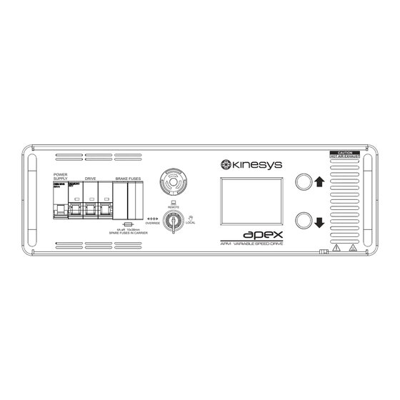
USER GUIDE 3 Overview 3.1.1 Layout This section describes the layout of the front panel controls and the rear panel connection option on an apexDRIVE 3.1.2 Front Panel Figure 1 Front panel layout 1. ‘Power Supply’ MCB – Used to isolate power to the control systems within the apexDRIVE, refer to page 22 for more details. -
Page 13: Rear Panel
USER GUIDE 3.1.3 Rear Panel 400V Version Figure 2 Rear panel layout (400V) 208V Version Figure 3 Rear panel layout (208V) 1. Air Intake Filters – Cooling air intakes for internal cooling fans. DO NOT OBSTRUCT. These feature replaceable filter media, refer to page 43 for more details. -
Page 14: Installation
The apexDRIVE shall only be truss mounted using the optional Truss Mount Bracket kit (Kinesys APM-01-0010) including the supplied Safety Bond. 4.1.1 Truss Mount Bracket (Primary Support) The truss mount bracket enables the apexDRIVE to be mounted on truss using (2/4) standard half couplers (not supplied). -
Page 15: Safety Bond (Secondary Support)
4.1.1.1 Installing the Trust mount Bracket Bolt the half couplers to the truss mount bracket to suit the truss layout; refer to Kinesys drawing 9200166 for layout of common truss types. Position the truss mount bracket on top of the apexDRIVE and locate the four DZUS fasteners onto the corresponding holes in the drive. -
Page 16: Rack Mount Kit
USER GUIDE 4.1.3 Rack Mount Kit A Rack Mount Kit is available to enable installation of the apexDRIVE in an industry standard 19” rack (3U height required). The rack mount kit includes: 1x pair of front ‘rack ear’ brackets ... -
Page 17: Figure 9 Rack Mount - Attaching Rack Slides To The Rack Frame
USER GUIDE 3) Checking the correct position, attach the rack slides to the rear of the rack using cage nuts and bolts. Figure 9 Rack mount - attaching rack slides to the rack frame 4) Use the rack guides on the side of apexDRIVE to slide the unit in to the fixed rack slide and line up the rack mount holes in the desired position. -
Page 18: Connections
The Ethernet standard states a 100m maximum link length between devices. In order to extend further than 100m the use of a fibre connection will be required. Please consult with Kinesys for further details on using a fibre connection with an apexDRIVE. -
Page 19: Mains Power Connection
USER GUIDE 5.2 Mains power connection The mains power connection to the apexDRIVE should always be the last connection made. The apexDRIVE is available configured for 400V mains supply or 208V mains supply. 5.2.1 400V apexDRIVE Power IN The 400V apexDRIVE is fitted with a 5-pole 32A type IEC 60309 CEE power connector and requires a 3 phase mains power supply with neutral (230V Ø-N, 400V Ø-Ø, 3Ø+N+E). -
Page 20: Power Cable Pinout Information
5.3 Power cable pinout information WARNING! Serious damage may be caused by misconnection of apexDRIVE. It is recommended that Kinesys supplied cables are used with apexDRIVE. The following sections detail the pinout of the power connections for the apexDRIVE . Wiring standards vary and there is always the possibility that pinouts on cables may not be compatible. -
Page 21: Hoist Connection
USER GUIDE 5.4 Hoist connection The hoist connection is made using a Harting modular connector with two locking levers. The apexHOIST has a captive tail cable assembly with a mating connector. Figure 17 (apexDRIVE) (apexHOIST) Figure 17 apexDRIVE and apexHOIST Harting connectors Check the orientation of the connector and socket, the connector can only be inserted one way round. -
Page 22: Circuit Protection
If the power MCB should trip in to the down position try to move the lever up to restore power. If the MCB immediately trips again this indicates a fault. Switch over to an alternative apexDRIVE and contact your supplier or Kinesys for support. WARNING! -
Page 23: Drive' Mcb
If the Drive MCB should trip in to the down position, try to move the lever back up to restore power. If the MCB immediately trips again this indicates a fault. Switch over to an alternative apexDRIVE and contact your supplier or Kinesys for support. WARNING! -
Page 24: Front Panel Controls
USER GUIDE 7 Front panel controls 7.1 Emergency Stop Figure 22 Emergency Stop button Each apexDRIVE is fitted with an Emergency Stop button. Pressing the Emergency Stop button at any time will stop all movement of the locally connected hoist as well as any apexDRIVE units connected to the same system. The Emergency Stop button will flash if it has been triggered and a fault condition will be displayed on the display. -
Page 25: Mode Key Switch
USER GUIDE 7.2 Mode Key switch Figure 23 Mode Key Switch The Mode Key Switch is used to define the preferred mode the drive will operate Override is used to set the apexDRIVE to be controlled manually from the front panel controls. In this mode certain limits may be overridden. Speed is deliberately limited in this mode. -
Page 26: Menu System Overview
USER GUIDE 7.3.1 Menu system overview Pressing the Home icon at any time will return the touch screen display to the home screen. Figure 24 ApexDRIVE menu system overview apexDRIVE User Guide 9200162 0v10... -
Page 27: Home Screen
USER GUIDE 7.3.2 Home screen Figure 25 Home screen The Home screen is the default menu screen. The background colour indicates the current status of the drive, RED for an alarm or fault, YELLOW for warnings, GREEN for OK. The Home screen also displays the following information: Drive Number indicates the specific number associated with the drive. -
Page 28: Alarms Screen
USER GUIDE 7.3.3 Alarms screen Figure 26 Alarm screen Press the Alarms icon from the Home screen or Manual control screen to display the Alarms screen which lists any current alarm conditions and status messages. A full list of alarm and status conditions can be found on page 37 to 38. Details Pressing any of the listed alarms followed by the Details icon will show more information on the current alarm, the status of the apexDRIVE or the connected apexHOIST. -
Page 29: Settings Screen
USER GUIDE 7.3.4 Settings screen Press the Settings icon to access the main settings screen from the Home screen. Figure 27 Settings screen 7.3.4.1 Brightness Press this icon to adjust the brightness of the touch screen display. Use the slider bar to set the desired brightness of the display. -
Page 30: Figure 30 Version Screen
USER GUIDE 7.3.4.3 Version Press this icon to display the apexDRIVE current software version. Figure 30 Version screen 7.3.4.4 Units Press this icon to configure the preferred measurement units for the apexDRIVE display. Select Imperial or Metric units using the arrows on either side of the screen. Figure 31 Units screen Next press this icon to access the engineering / support section of the... -
Page 31: Hoist Information
Effective RunTime Hours hoist accumulated running time in hours based on current running conditions. This time in hours determines when the hoist requires servicing. This value is reset by Kinesys during servicing. Total Eff RunT Hours hoist usage time overall. This value cannot be cleared. -
Page 32: Operation
USER GUIDE 7.4 Operation 7.4.1 Manual [LOCAL] operation Figure 33 Display screen Each apexDRIVE has the facility to control the apexHOIST directly from the front panel controls. To access manual controls turn the Mode Key Switch to the LOCAL position. The following screen will be displayed on the touch screen display. -
Page 33: Manual [Override] Operation
USER GUIDE While moving a connected apexHOIST using manual controls, the ramp up and down speed is fixed and determined by the speed of movement. This is adjustable when controlling hoists remotely using Vector or K2 motion control software. Alarms Pressing this icon will display the Alarm screen. See page 28 for details. -
Page 34: Remote [Remote] Operation
For more details on the Mentor 401 and its connections please refer to the operating manual for the Mentor 401. Contact either your local Kinesys distributor or Kinesys directly. apexDRIVE User Guide 9200162 0v10... -
Page 35: Troubleshooting Guide
Refer to pages 36. This screen also allows configuration of the e-stop system to allow compatibility with Kinesys ‘EVO v2’ based e-stop controllers, refer to section 8.1.1 on page 36. apexDRIVE User Guide 9200162 0v10... -
Page 36: E-Stop Configuration
Refer to the fault code tables in this chapter. Check the reported fault code against the relevant list and follow the suggested course of action. If a fault is not listed (or states ‘Refer to Kinesys’) contact either your reseller or Kinesys directly for further technical support. -
Page 37: Alarm Conditions
Alarm Description Action Brake Fuse Fault There is a fault with the brake Replace the fuse if possible or contact Kinesys fuse. Support. A Dead Man’s Handle is not active The switch on a dead man’s handle connected in the system to the system is not being pressed to release movement. -
Page 38: Alarm Conditions Continued
Status Description Action EVO V2 ON Legacy e-stop mode selected No action required if using Kinesys DC8 e-stop hub. If using Mentor 40x then use the icon on Safety Status screen to select APEX. Apex Mentor safety Mentor 40x series controlled... -
Page 39: Status Conditions Continued
USER GUIDE 8.5 Status Conditions continued Status Description Action Decelerating The connected apexHOIST is decelerating from its set speed to a stopped position Stationary The connected apexHOIST is currently stationary Safe Up Limit The hoist has reached the limit of The apexHOIST will not move past this point. -
Page 40: System Menu
Each apexDRIVE has an Engineering / Support sub menu which is password protected. This menu is only used for technical support and repair. Access to this menu is not required for normal operation of the apexDRIVE. Please contact Kinesys for more details. -
Page 41: Figure 40 Numeric Keypad For Password Entry
Enter the password when the numeric keypad appears: Figure 40 Numeric keypad for password entry Note! For safety reasons password access is strictly limited to Kinesys and other trained personnel. Refer to service manual or training documentation for use of protected menu functions. -
Page 42: Maintenance & Repair
In normal use no user maintenance should be required beyond periodic functional and safety testing, basic cleaning and filter replacement. In the event of damage or premature failure please contact Kinesys, or your local distributor to arrange service support or repair. -
Page 43: Checking And Replacing Air Intake Filters
It is recommended to check the condition of filters regularly. Depending on the nature of the contamination it may be possible to clean the filter media. Alternatively, packs of spare filter media can be supplied by Kinesys to allow replacement when needed. -
Page 44: Recalibration Of Touchscreen
USER GUIDE 10 Recalibration of Touchscreen The display touchscreen is calibrated during manufacture and, usually, should not require recalibration. However if the screen is replaced or it is found that, in use, icons do not respond centrally to touch, then recalibration should be carried out. IMPORTANT! Before starting please confirm that the apexDRIVE is level and positioned with the front panel text readable left to right as shown in Figure 41: Figure 41 Correct orientation of apexDRIVE for screen calibration... -
Page 45: Product Specification
USER GUIDE 11 Product specification Feature Specification Environmental Operating Temperature Range 5C to 40C Storage & Transportation Temperature Range -25C to + 55C Humidity RH <50% at maximum 40C Altitude 1000m For indoor use only! Mains power supply 400V version 3Ø+N+E 47-63Hz, 9A / Ø... - Page 46 USER GUIDE Brakes – 4A gR 10x38mm ‘CC’ fuse (x2) ApexHOIST interface Multi-function Harting connector Kinesys apexHOIST Motor 208V / 400V compatibility Nominal 3kW (4hp) maximum Do NOT connect other hoist types Brakes 205V DC Front panel controls Resistive touch screen TFT...
- Page 47 USER GUIDE Dimensions 423mm x 132mm x 520mm (excluding handles, connectors, cabling and mounting hardware) Refer to Kinesys drawings: 9200174 (400V) or 9200175 (208V) 3U 19” rack mount Rack mount Truss mount Optional truss mounting kit APM-01-0010 including safety bond Refer to Kinesys drawings: 9200174 (400V) or 9200175 (208V) &...
-
Page 48: Declaration Of Conformity
USER GUIDE 12 Declaration of Conformity An individual Declaration of Conformity shall be provided with each apexDRIVE: apexDRIVE User Guide 9200162 0v10... -
Page 49: Packaging
15 Spare parts The following table shows some common spare parts and accessories for the apexDRIVE. This is not an exhaustive list. Please contact Kinesys, or your local distributor for any component that is not listed. Item... - Page 50 USER GUIDE Back Page. apexDRIVE User Guide 9200162 0v10...
Need help?
Do you have a question about the apexDRIVE Series and is the answer not in the manual?
Questions and answers