Table of Contents
Advertisement
Advertisement
Table of Contents

Subscribe to Our Youtube Channel
Related Manuals for Kinesys Elevation 1 Plus

Summary of Contents for Kinesys Elevation 1 Plus
- Page 1 Elevation 1+ Product Manual Manual Version 1.8.0 © 2011 Kinesys Projects Ltd...
- Page 2 Elevation 1+ © 2011 Kinesys Projects Ltd All rights reserved. No parts of this work may be reproduced in any form or by any means - graphic, electronic, or mechanical, including photocopying, recording, taping, or information storage and retrieval systems - without the written permission of the publisher.
-
Page 3: Table Of Contents
Part 14 System Integration 1 Elevation 1+ System Diagram Simple ........................... 30 2 Elevation 1+ Full System Diagram ........................... 31 Part 15 Replacing an Elevation Part 16 Using an Elevation with RCDs Part 17 Contact Information © 2011 Kinesys Projects Ltd... -
Page 4: Part 1 Introduction
© 2011 Kinesys Projects Ltd... -
Page 5: Part 2 Safety Advice
• Use extreme caution when using any limit bypass facilities in the system. • Carry out a full risk assessment for your particular application. • Only allow competent personnel to operate the system. © 2011 Kinesys Projects Ltd... -
Page 6: Left Side
Elevation 1+ Left Side 1. Mains Inlet Gland - supplied with cable to a 32A 3PN+E plug. 2. Mains Outlet Connector - unprotected pass-through. 3. Air Intake Grilles - these must not be obstructed or blocked. © 2011 Kinesys Projects Ltd... -
Page 7: Part 4 Right Side
5. Fan Outlet – this must be kept clear at all times to allow the free flow of air through the unit. 6. Hoist Connection – motor, brake and control voltage to the hoist, limit and encoder feedback from the hoist are all provided through this connector. © 2011 Kinesys Projects Ltd... -
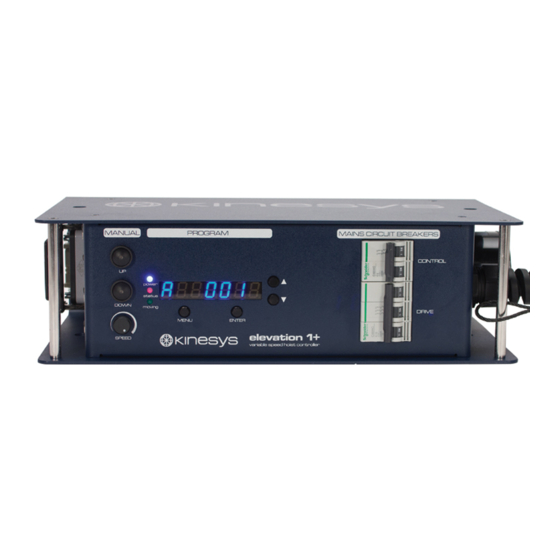
Page 8: Part 5 Front View
8. Manual Up Button – enables the hoist to be run upwards locally without the use of an external controller. 9. Manual Down Button – enables the hoist to be run downwards locally without the use of an external controller. 10.Manual Speed Control – set the speed of all local manual moves. © 2011 Kinesys Projects Ltd... -
Page 9: Part 6 Specifications
RS485 specification Control Signals 0 - 24v d.c. Emergency Stop Single wire 12v system – category 2 rated Dimensions 424w x 240h x 130d Excluding fixing hardware and cable glands Weight 9.5 Kg Excluding fixing hardware © 2011 Kinesys Projects Ltd... -
Page 10: Part 7 Cable Specification
Cable: 5-core 6mm² 400V/700V rated (H07) e.g. Lapp Cable 1600 1313 (H07RN-F) for portable use Cable Colour Code Function Colour Earth green/yellow L1/R Live 1 brown L2/S Live 2 black L3/T Live 3 grey Neutral blue © 2011 Kinesys Projects Ltd... -
Page 11: Part 8 Software
A complete list of menus and parameters is included in this manual. The majority of parameters can also be downloaded from the controlling computer allowing rapid initial set-up and alteration of these settings. © 2011 Kinesys Projects Ltd... -
Page 12: Part 9 Menus
This timer is reset to 2 minutes every time the unit is run in manual mode. After two minutes of inactivity the unit will revert to automatic mode as if the menu and enter buttons had been pressed. © 2011 Kinesys Projects Ltd... -
Page 13: Menu Operation
Pressing enter will save the new value and return to the previous sub-menu. The scroll is variable speed with the speed of value change increasing the longer the button is pressed. © 2011 Kinesys Projects Ltd... -
Page 14: Fault Conditions
OSpeed - Overspeed detected, the motor is traveling faster than demanded USpeed - Underspeed detected, the motor is traveling slower than demanded Udog - Comms watchdog trip, a status stationary message was received while a move was in progress © 2011 Kinesys Projects Ltd... - Page 15 (Shown on display for 15 seconds after timeout occurs, even if comms returns - cleared after 15 seconds) Enc 1 - No encoder count detected Enc 2 - Encoder reversed Emergency Stop Trip Unit is resetting Running ROM firmware. Firmware update required © 2011 Kinesys Projects Ltd...
-
Page 16: Menu Structure
Upper Data Max Lower Travel Lower Bypass Default selectable when ultimate struck Ultimate Bypass Default setting Data mm/s Speed Default mm/s/s Data Accel mm/s/s Data Decel Data mm/s/s Fast Decel © 2011 Kinesys Projects Ltd... - Page 17 Data Speed Data Accel Data Decel Data Offset Data Down Data Encoder Pulses per mm Encoder Data Proportional Gain Parameters Integral Gain Data Data Derivative Gain © 2011 Kinesys Projects Ltd...
- Page 18 Elevation 1+ Data Min Drive Speed Max Drive Speed Data Data Pos Trip Distance Data Default Analog Default Display Flip Comms Comms Address Data Address Data Current Position Data Position © 2011 Kinesys Projects Ltd...
- Page 19 Menus Data Software Version Version Product Identification Code Data Product ID Product License Code Data License © 2011 Kinesys Projects Ltd...
-
Page 20: Part 10 Position Controller
(Default value 5000 = 100hz) The maximum raw speed value that can be sent to the drive. This value is measured in units of 0.02Hz. Used to set the maximum drive speed that may be permitted. This value © 2011 Kinesys Projects Ltd... - Page 21 This is the amount of time that the brake release is delayed on start. This gives the drive time to build up current to hold the load. This parameter needs to be set to a value other than 0 only for very fast acting brakes. © 2011 Kinesys Projects Ltd...
-
Page 22: Part 11 Unit Configuration
10,000. If you are using V4.xx elevation software or below then divide the encoder scaling by a factor of 10. Hoist Model Old Enc Scale Enc Scale <= V4.xx >= V5.00 LodeStar LL 7590 © 2011 Kinesys Projects Ltd... - Page 23 Switching frequency of the inverter. These are factory set to a value of 45000 for the boost and 20000 for the switching frequency. These values only need to be modified if instructed to by Kinesys. They can be set by accessing drive parameters 16 (Boost) and 18 (Switching Frequency) in Vector or K2.
-
Page 24: Part 12 Limits
An ultimate limit trip will be shown on the menu display on the unit and reported back to the controlling computer. Ultimate Limit Override Due to the severity off hitting an ultimate limit both a software and hardware bypass is © 2011 Kinesys Projects Ltd... - Page 25 Once the limit is cleared the ultimate bypass parameter in the menu will automatically clear itself and normal operation can be resumed. © 2011 Kinesys Projects Ltd...
-
Page 26: Setting The Software Travel Limits Without A Computer
Limit (mm) Limits Upper Max Lower Travel Data Limit (mm) Lower Data Data Current Position (mm) Position For example if a hoist was run to its lowest position, which was 1000mm off the stage, © 2011 Kinesys Projects Ltd... - Page 27 It should be noted that an Elevation may have old limits programmed into it and these may cause movement to stop before the desired position is reached. In this case the existing limits would need to be opened out. © 2011 Kinesys Projects Ltd...
-
Page 28: Part 13 Manual And Remote Running
The hoist is ramped up and down when the run buttons on the pendant are pressed and released and the buttons must be held during the entire movement of the hoist. © 2011 Kinesys Projects Ltd... -
Page 29: Part 14 System Integration
Ethernet and RS485 is done by a Transform 485 unit which is either supplied as a stand-alone unit or is integrated into the power distribution rack to create a very compact control solution. © 2011 Kinesys Projects Ltd... -
Page 30: Elevation 1+ System Diagram Simple
Elevation 1+ 14.1 Elevation 1+ System Diagram Simple © 2011 Kinesys Projects Ltd... -
Page 31: Elevation 1+ Full System Diagram
System Integration 14.2 Elevation 1+ Full System Diagram © 2011 Kinesys Projects Ltd... -
Page 32: Part 15 Replacing An Elevation
The following parameters are normally the same for all Elevation 1+ controllers connected to the same type of motor within an installation. Their values should be checked on the replacement controller. © 2011 Kinesys Projects Ltd... - Page 33 Data mm/s/s Accel mm/s/s Data Decel mm/s/s Data Fast Decel Data Clamps Speed Data Accel Data Decel Data Speed Data Accel Data Decel Data Offset © 2011 Kinesys Projects Ltd...
- Page 34 Encoder Pulses per mm Data Encoder Proportional Gain Data Parameters Data Integral Gain Derivative Gain Data Data Min Drive Speed Max Drive Speed Data Data Pos Trip Distance Data © 2011 Kinesys Projects Ltd...
-
Page 35: Part 16 Using An Elevation With Rcds
Using an Elevation with RCDs Using an Elevation with RCDs The Kinesys Elevation 1+ is designed to comply with European legislation for variable speed drives, which require that an RFI (Radio Frequency Interference) filter is included to prevent the noise generated by the drive from interfering with nearby computer systems, radio equipment etc. -
Page 36: Part 17 Contact Information
Elevation 1+ Contact Information If you would like to get in touch with Kinesys then please use any of the following methods. Email: info@kinesys.co.uk Website: www.kinesys.co.uk Tel: +44 (0) 20 8481 9850 Fax: +44 (0) 20 8487 0396 Mail: Unit 2 Kempton Gate Business Centre...
Need help?
Do you have a question about the Elevation 1 Plus and is the answer not in the manual?
Questions and answers