Table of Contents
Advertisement
Advertisement
Table of Contents

Subscribe to Our Youtube Channel
Related Manuals for Yamaha C-5000


Summary of Contents for Yamaha C-5000
- Page 1 Pre-Amplifier Owner´s Manual...
-
Page 2: Features
¡ To use the product properly and safely, we suggest that you read this manual and Safety Brochure (separate booklet) thoroughly. Keep the manual in a safe, accessible place for future reference. You can download a PDF version of this manual from the following Yamaha website. https://download.yamaha.com/ Features ¡... -
Page 3: Table Of Contents
Operating the unit from another room . . 25 Remote connection between Yamaha components . . . . . . . . . . . . . . . . . . . 25... -
Page 4: Supplied Accessories
. • If you wipe the surface area in the vicinity of the Yamaha logo with force, the logo might peel off or fiber from the cloth might stick to the surface . -
Page 5: Part Names And Functions
Part Names and Functions This section lists the names and describes the function of various parts on the front and rear panels, and the remote control. -
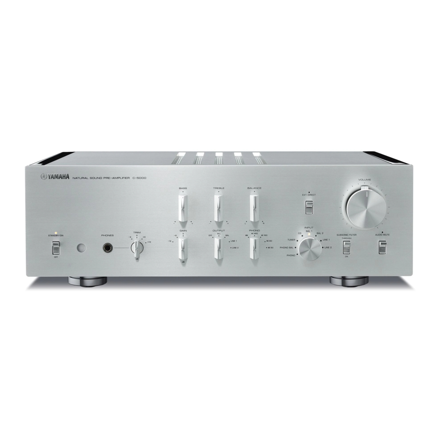
Page 6: Front Panel
Front panel STANDBY/ON/OFF (Power) Note switch/ indicator After you turn on the unit, it will take a few seconds before the unit can reproduce sound . Turns the power to the unit on (standby) or off. STANDBY/ON: Switches between standby and on using NOTICE the A AMP key on the remote control. - Page 7 TRIM selector OUTPUT selector Switches the headphone amp gain. The unit will adjust LINE1 LINE2 the volume level when headphones are plugged in to avoid sudden changes in volume by modifying the level — Output Output — — balance between the audio output from the PHONES jack jacks and from the speakers.
- Page 8 Front panel BASS control EXT. DIRECT switch/indicator Adjusts the low-frequency response in the range from If you press the EXT. DIRECT switch once, the EXT. −10 dB to +10 dB (in 0.5 dB steps). The center position DIRECT indicator will light up, and the audio source produces a flat response.
- Page 9 µ ¸ ¹ INPUT selector/indicator AUDIO MUTE switch/indicator Enables you to select the input source to play back. Press this switch to reduce the current volume level by Options are: PHONO, PHONO BAL, TUNER, CD, BAL 1, approximately 20 dB. The indicator will light up. Press BAL 2, LINE 1, and LINE 2.
-
Page 10: Rear Panel
Rear panel Note CAUTION For information regarding the connection procedure, refer to “Connections” (page 19) . Handle the shorting plugs carefully . Do not allow children to play with the shorting plug; otherwise they might swallow it . PHONO jacks NOTICE RCA and XLR-type jacks. - Page 11 * The illustration above shows the model for Europe BAL 1/BAL 2 jacks PHASE selector These are two sets of XLR-type balanced input jacks. If Specifies the HOT pin position for the XLR-type the INPUT selector is set to BAL 1 or BAL 2, signals at balanced input jacks (BAL 1 and BAL 2 jacks).
- Page 12 Rear panel µ CD jacks Note • Connect the LINE 2 IN jacks and LINE 2 OUT (recording) These are RCA input jacks. If the INPUT selector is set jacks to the same component . to CD, signals at these jacks will be the input source. • The LINE 2 OUT (recording) jacks will not output any Connect your CD player here.
- Page 13 µ ¸ ¹ * The illustration above shows the model for Europe REMOTE IN/REMOTE OUT jacks Note The volume level is fixed . Operating the VOLUME control or These are monaural mini jacks. Connect external GAIN selector on this unit will not change the volume level components that support the remote function here.
-
Page 14: Balanced And Unbalanced Connections
. The pin polarity of these jacks is standard and Lever fixed . • Pin #2 is Hot on Yamaha players . When connecting a cable to an input jack, be sure to align the pins on the connector with the holes in the jack, and then insert the connector into the jack until you hear a click. - Page 15 Unbalanced connection If you are connecting an audio component that features only standard RCA jacks, use the RCA jacks on this unit for unbalanced connections. For unbalanced connections, unbalanced cables with RCA connectors should be used. These jacks and connectors do not feature a male or female design nor polarity differences.
-
Page 16: Remote Control
Tuner control keys Enable you to control the functions of the connected MUTE Yamaha tuner. Use the BAND key to switch the reception band, and the PRESET er keys to select a preset station. For more information, refer to the owner’s manual for your tuner. - Page 17 A CD key VOLUME +/− keys Turns on the power to a connected Yamaha CD player, or Adjust the volume level. switches it to standby mode. Note The VOLUME +/− keys on the remote control will not affect OPEN/CLOSE key the volume level if EXT .
-
Page 18: Installing Batteries In The Remote Control
Installing batteries in the remote CAUTION control • Do not use a new and old batteries at the same time . Otherwise, fire, burns, or irritation due to leaking battery liquid might be caused . Remove the battery compartment cover • Do not use two different types of batteries at the same time . -
Page 19: Connections
Connections This section explains how to connect the unit to an audio source, such as a tuner or CD player, and a power amplifier. CAUTION Turn off the power to all components before making any connections . NOTICE • Do not use balanced and unbalanced connections between two components simultaneously . Doing so would create a ground loop that could generate static and noise . -
Page 20: Connecting An External Component
Connecting an external component Turntable Turntable CD player CD player BD player Network audio player Tuner Hard disk recorder,... - Page 21 Other preamplifier Power amplifier Active subwoofer AV amplifier, etc Power amplifier NOTICE Do not use balanced and unbalanced connections between two components simultaneously . Doing so would create a ground loop that could generate static and noise .
-
Page 22: Connecting A Turntable
Connecting a turntable Connecting a recording component Connect your turntable to the PHONO jacks on this unit. The unit provides XLR-type balanced jacks and RCA- You can connect a recording device, such as a hard disk type unbalanced input jacks. recorder to the unit, and record audio input from the unit. -
Page 23: Connecting Another Preamplifier
Connecting another Connecting a power amplifier preamplifier and an active subwoofer If you connect the output of another preamplifier to the You can connect a power amplifier and an active EXT. IN jacks on this unit and press the EXT. DIRECT subwoofer to the BAL, LINE 1, or LINE 2 output jacks switch, the source signal will pass through the unit and on this unit. -
Page 24: Trigger Connections
You can control the unit’s power on-and-off operation connected component, such as a Yamaha CD player or in sync with a connected component, such as a Yamaha power amplifier, in sync with this unit. AV receiver. Use an optional system cable to connect the unit’s TRIGGER IN jack to the connected component’s... -
Page 25: Remote Connections
Yamaha components If you connect an infrared receiver and transmitter to If you have another Yamaha component that supports the unit’s REMOTE IN/OUT jacks, you will be able to remote connections, as this unit does, an infrared operate the unit and/or external component from another transmitter is not necessary. -
Page 26: Connecting The Power Cord
Otherwise, continued use of the unit might lead to electric shock, fire, or malfunction . Contact your nearest Yamaha dealer or service center for check-up or repair . • Do not touch the power cord or plug during lightning storms . Otherwise, an electric shock might be caused . -
Page 27: Operations
Operations This section explains basic operating procedures. You can follow these procedures to take advantage of the unit’s functions. These procedures are intended only as examples. -
Page 28: Turning The Power On
Turning the power on Selecting the input and output CAUTION Select a pair of output jacks using the OUTPUT selector. Be sure to lower the volume level to minimum before turning the power on . Turn the power on by setting the STANDBY/ON/OFF (Power) switch on the front panel to STANDBY/ON. -
Page 29: Selecting The Input From The Ext.in Jacks
Adjusting the turntable input Selecting the input from the setting EXT.IN jacks PHONO selector Set the PHONO selector according to the turntable cartridge. Options for turntable cartridge Press the EXT. DIRECT switch. The EXT. DIRECT MM-type cartridge indicator will light up. The INPUT selector setting will be disabled, and the audio source input from the EXT. -
Page 30: Subsonic Filter
Adjusting the volume level Subsonic filter Set the gain using the GAIN selector so that you can Turn on the SUBSONIC FILTER switch to apply the subsonic filter, as needed. make fine volume adjustments. A resonating turntable tone arm or a warped vinyl record could cause a very low frequency rumble (subsonic noise) that might apply load and damage to the speakers. -
Page 31: Lowering The Volume Level Momentarily
Adjusting the tone Adjust the volume level balance between the left and Lowering the volume level right speakers using the BALANCE control. momentarily Press the AUDIO MUTE switch to reduce the current volume level by approximately 20 dB. Press the switch again to restore the previous volume level. -
Page 32: Connecting Headphones
Connecting headphones If headphones are connected to the PHONES jack, no signal will be output at the output jacks (BAL, LINE 1, and LINE 2 output jacks) on the rear panel. Use the TRIM selector to switch the headphone amp gain so you can adjust the level balance between the audio output from the PHONES jack and the speakers to avoid sudden changes in volume. -
Page 33: Reference Materials
Reference Materials... -
Page 34: General Specifications
General specifications Rated output voltage/output impedance Total harmonic distortion plus noise (Input 200 mV, 20 Hz to 20 kHz, THD 0 01%) (JEITA, input 0 5 V, 20 Hz to 20 kHz) BAL (BYPASS) ....2 Vrms/150Ω BAL 1/BAL 2/TUNER/CD/LINE 1/LINE 2 IN →... - Page 35 ........19.1 kg * The contents of this manual apply to the latest specifications as of the publishing date. To obtain the latest manual, access the Yamaha website then download the manual file.
-
Page 36: Block Diagram
Block diagram SUBSONIC FILTER TONE CONTROL... -
Page 37: Audio Characteristics
Audio characteristics Frequency response (tone control) +10dB +8dB +6dB +4dB +2dB ±0dB –2dB –2 –4dB –4 –6dB –6 –8dB –8 –10dB –10 –12 –14 200 300 100k Frequency (Hz) Total harmonic distortion (PHONO) 20 Hz 1 kHz 20 kHz 0.05 0.02 0.01 0.005... -
Page 38: Frequency Response (Subsonic Filter)
Frequency response (subsonic filter) THROUGH –5 –10 –15 –20 –25 200 300 20k 30k 100k Frequency (Hz) Volume curve GAIN selector: –6 dB –20 GAIN selector: 0 dB –40 GAIN selector: –12 dB –60 –80 –100 –110 0.00 50.00 100.00 150.00 200.00 250.00... -
Page 39: Troubleshooting
Refer to the table below if this unit does not function properly. If the instructions below do not help, or if the problem you are experiencing is not listed below, turn off the unit, disconnect the power cord, and contact the nearest authorized Yamaha dealer or service center. Problem... - Page 40 Problem Cause Remedy page Connect the cables properly. If the Incorrect input or output cable problem persists, the cables might be connections. defective. The turntable is not grounded to Connect the turntable to the GND A “humming” noise is the GND terminal. terminal of this unit.
-
Page 41: Index
Index AC IN jack ....... 26 OUTPUT selector ......28 Adjusting the turntable input . - Page 44 Yamaha Global Site https://www.yamaha.com/ Yamaha Downloads https://download.yamaha.com/ Manual Development Group © 2018 Yamaha Corporation Published 10/2018 IPEM-A0 VAQ1810 10-1 Nakazawa-cho, Naka-ku, Hamamatsu, 430-8650 Japan...
Need help?
Do you have a question about the C-5000 and is the answer not in the manual?
Questions and answers