Table of Contents
Advertisement
Advertisement
Table of Contents

Subscribe to Our Youtube Channel
Related Manuals for Liquid Controls CENTRILOGiQ LCR.iQ

Summary of Contents for Liquid Controls CENTRILOGiQ LCR.iQ
-
Page 2: Table Of Contents
Table of Contents Adobe PDF Manuals ..................... 4 Register Overview ......................5 Publication Updates ..................... 6 Safety Procedures ....................... 7 ESD Protection ......................9 Specifications ......................11 Regulatory & Certifications ..................16 FCC Compliance ......................19 Dimensions - Panel Mount ..................22 Dimensions - Meter Mount .................. - Page 3 LCR.iQ/MasterLoad.iQ Product Manual LCR.iQ/MasterLoad.iQ Product Manual Congratulations on ownership of the new LCR.iQ or MasterLoad.iQ electronic meter register and controller. This manual provides the technical details on installation, hardware, setup, operation, and regulatory information for your register. NOTE: Throughout this manual, both the LCR.iQ and MASTERLOAD.iQ are referred to as “Register”...
-
Page 4: Adobe Pdf Manuals
LCR.iQ/MasterLoad.iQ Product Manual Adobe PDF Manuals Download either of the manuals using the links below: · Liquid Controls LCR.iQ / MASTERLOAD.iQ Installation Manual · Liquid Controls LCR.iQ / MASTERLOAD.iQ Operations Manual To begin reading the online help, start with the... -
Page 5: Register Overview
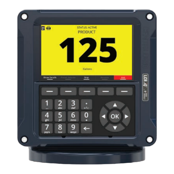
Register function keys and alphanumeric keypad. No lap pads, laptops, or other data entry devices are required. A complete Liquid Controls meter system not only accurately measures product, it also regulates product flow and removes contaminants in order to produce the optimal conditions for measurement. -
Page 6: Publication Updates
LCR.iQ/MasterLoad.iQ Product Manual Publication Updates The most current versions of all Liquid Controls publications are available on our web site, www.LCmeter.com/resources/technical/manuals. If there are questions about the language or interpretation of any LC manuals, instructions, or specification sheets, please first contact your local distributor for help with your inquiry. -
Page 7: Safety Procedures
LCR.iQ/MasterLoad.iQ Product Manual Safety Procedures BE PREPARED · Before using this product, read and understand the instructions. · All work must be performed by qualified personnel trained in the proper application, installation, and maintenance of equipment and/or systems in accordance with all applicable codes and ordinances. ·... - Page 8 LCR.iQ/MasterLoad.iQ Product Manual OBSERVE NATIONAL & LOCAL CODES Power, input, and output (I/O) wiring must be in accordance with the area classification for which it is used (Class I, Div 2). For North America, installations must be per the U. S. National Electrical Code, NFPA 70, or the Canadian Electrical Code in order to maintain Class I, Division 2 ratings.
-
Page 9: Esd Protection
This electric charge can enter the Register from any point in the truck electrical system, including register power and printer cabling. Liquid Controls Grounding Kits All truck installations of the Register must have grounded seats and printers using the following kits: ·... - Page 10 LCR.iQ/MasterLoad.iQ Product Manual The Epson Printer Ground Wire Kit is included with each Epson printer cable kit shipment. For existing installations and previously purchased registers / printers, both ground kits are available from LC. Grounding with a Meter Mount or Remote Mount In an installation where the Register is mounted directly to the meter, the Register housing is grounded through the meter.
-
Page 11: Specifications
LCR.iQ/MasterLoad.iQ Product Manual Specifications Mechanical Housing and Keypad The Register housing and bases are aluminum die castings with chromate protective finishing and powder coated with high durability, urethane powder. The cover internal hinge design provides easy access to the internal connections and keeps all moving hinge parts out of the elements to further prevent corrosion. - Page 12 LCR.iQ/MasterLoad.iQ Product Manual · 800 x 480 pixels (152.4 mm x 91.4 mm) · Luminance: 1500 (cd/m · Display acceptable operation or storage temperature -40 °F to 185 °F (-40 °C to 85 °C). Weight · Approximately 12 lbs (Meter Mount Version, no added accessories) ·...
- Page 13 (meter mount option only). A pulse input can also come from an external device such as a Liquid Controls Pulse Output Device (POD) or another externally mounted pulse generator. If an external LC POD is purchased, these materials are necessary, but are not supplied with the POD: ·...
- Page 14 LCR.iQ/MasterLoad.iQ Product Manual · Voltage: 5 to 28 VDC · Current: 3 mA maximum sink current · Maximum Frequency: 10 kHz OUTPUTS The Register is equipped with six digital outputs and four solenoid outputs. These outputs allow the Register to communicate with meter system accessories such as solenoid- controlled valves, optical air and vapor eliminators, remote displays, printers, and third-party devices.
- Page 15 LCR.iQ/MasterLoad.iQ Product Manual Electrical Protection · 5 A fuse on power cable COMMUNICATIONS · RS-232 · RS-485 · CAN BUS – Consult the applicable Chassis Builder’s Guide, available from the truck chassis manufacturer. · Ethernet (Gigabit) · Bluetooth (wireless) · Wi-Fi (wireless) Printer (Epson Model 295) ·...
-
Page 16: Regulatory & Certifications
LCR.iQ/MasterLoad.iQ Product Manual Regulatory & Certifications The equipment is Listed by UL to applicable US and Canadian standards for use in hazardous locations under Liquid Controls file E180172. LCR.iQ Serial Number tag MASTERLOAD.iQ Serial Number tag Class I · Potentially Explosive Gas/Vapor Atmospheres. - Page 17 LCR.iQ/MasterLoad.iQ Product Manual Division 2 and Zone II · Gases and vapor are not normally present in an explosive concentration but may accidentally exist during abnormal operations. Grp C&D and Grp IIB · Flammable/explosive Gas groups. · ambient temperature. At the rated maximum ambient temperature, the equipment will not generate temperature higher than 135 °C ·...
- Page 18 LCR.iQ/MasterLoad.iQ Product Manual Specifications Get the latest PDF manual: https://www.lcmeter.com/resources/technical/manuals Mobile/online version of this manual: https://www.lcmeter.com/manuals...
-
Page 19: Fcc Compliance
LCR.iQ/MasterLoad.iQ Product Manual FCC Compliance Unique Identifier: LCR.iQ or MasterLoad.iQ Responsible Party: Liquid Controls LLC 105 Albrecht Drive Lake Bluff, IL 60044 USA www.LCmeter.com FCC Compliance Statement: This device complies with Part 15 of the FCC Rules. Operation is subject to the following two conditions: (1) This device may not cause harmful interference, and (2) this device must accept any interference received, including interference that may cause undesired operation. - Page 20 · Consult the dealer or an experienced radio/TV technician for help. Any changes or modifications to this equipment, not expressly approved by Liquid Controls could void the user’s authority to operate the equipment. This device complies with the ISED Canada license-exempt RSS standard(s). Operation is...
- Page 21 LCR.iQ/MasterLoad.iQ Product Manual The antenna for this equipment shall not be co-located with or operated in conjunction with any other antenna or transmitter. The antennas shall be installed and operated to maintain a separation distance of 20 cm or greater between any other radiating antenna. The FCC ID and IC can also be viewed on the Register by pressing <Main Menu>...
-
Page 22: Dimensions - Panel Mount
LCR.iQ/MasterLoad.iQ Product Manual Dimensions - Panel Mount FRONT VIEW BACK VIEW Get the latest PDF manual: https://www.lcmeter.com/resources/technical/manuals Mobile/online version of this manual: https://www.lcmeter.com/manuals... - Page 23 LCR.iQ/MasterLoad.iQ Product Manual SIDE VIEW TOP VIEW Get the latest PDF manual: https://www.lcmeter.com/resources/technical/manuals Mobile/online version of this manual: https://www.lcmeter.com/manuals...
-
Page 24: Dimensions - Meter Mount
LCR.iQ/MasterLoad.iQ Product Manual Dimensions - Meter Mount Front View Get the latest PDF manual: https://www.lcmeter.com/resources/technical/manuals Mobile/online version of this manual: https://www.lcmeter.com/manuals... - Page 25 LCR.iQ/MasterLoad.iQ Product Manual Side view Top View Bottom View Get the latest PDF manual: https://www.lcmeter.com/resources/technical/manuals Mobile/online version of this manual: https://www.lcmeter.com/manuals...
-
Page 26: Installation
LCR.iQ/MasterLoad.iQ Product Manual Installation Check Each Shipment Before installation, check your shipment against the packing list and ensure that no parts are missing. The packing list is inside the red information packet along with the Installation and Operation Manuals. If the Register was ordered as part of a metering system, it may arrive mounted on the meter and pre-wired to peripheral equipment such as an ETVC probe, air eliminator, and valve. - Page 27 LCR.iQ/MasterLoad.iQ Product Manual 7. Setup and calibrate the Register. What this chapter covers This chapter explains and details the mechanical installation of the Register and the temperature probe as well as the electrical and data installation of all components that connect to the Register.
- Page 28 LCR.iQ/MasterLoad.iQ Product Manual Wiring Diagram For better viewing of this diagram, click this link to download a high-resolution PDF image: Full- size wiring diagram. Get the latest PDF manual: https://www.lcmeter.com/resources/technical/manuals Mobile/online version of this manual: https://www.lcmeter.com/manuals...
- Page 29 LCR.iQ/MasterLoad.iQ Product Manual Get the latest PDF manual: https://www.lcmeter.com/resources/technical/manuals Mobile/online version of this manual: https://www.lcmeter.com/manuals...
- Page 30 LCR.iQ/MasterLoad.iQ Product Manual Ground Strap Kit All seat cushions are grounded in a similar manner. The illustrations below detail the following instructions for grounding three typical types of truck seats. ESD Precaution Install the Ground Strap Kit before installing the register. Follow these steps to ground a truck seat: 1.
- Page 31 LCR.iQ/MasterLoad.iQ Product Manual Ensure a Good Ground Remove any dirt or oxidation from the ground strap contact point. Lock washers should penetrate any paint to ensure a good electrical connection. 4. Find an existing screw or hole, or drill a 9/32” hole, in the part of the seat frame—above all pivots and adjustments—that is attached directly to the seat cushion.
-
Page 32: Attach Ground Strap
LCR.iQ/MasterLoad.iQ Product Manual Attach Ground Strap Typical Adjustable Truck Seats The diagrams below demonstrate how to attach the ground strap to typical truck seats. Air Cushion Seat - Adjustable for Height Bench Seats - Adjustable for Distance to the Steering Wheel Get the latest PDF manual: https://www.lcmeter.com/resources/technical/manuals Mobile/online version of this manual:... -
Page 33: Check For A Good Ground
LCR.iQ/MasterLoad.iQ Product Manual Check for a Good Ground After installing the ground kits, use a multimeter to confirm that the seat and printer are both grounded properly. Follow these steps to verify a good ground connection: 1. Turn OFF all accessories, including the dome light, to prevent other currents from distorting the reading. -
Page 34: Mounting Overview
LCR.iQ/MasterLoad.iQ Product Manual Mounting Overview The Register is available in two separate mounting options: meter mount and panel mount. The Register can be mounted directly onto a flow meter; however, it may also be mounted away from the meter in a more ergonomic or advantageous position, on a control panel or control pedestal. - Page 35 LCR.iQ/MasterLoad.iQ Product Manual Panel Mount Housing Adapters are available for other PD meters such as Neptune (PNs 81364, 82641, 82642), FMC Smith (PN 81370), and Brooks/Brodie (PN 81800) meters. Each kit includes installation instructions. Tips for mounting a Register · Leave the cover assembly fastened to the base to protect the internal components.
- Page 36 LCR.iQ/MasterLoad.iQ Product Manual WARNING Relieving Internal Pressure All internal pressure must be relieved to zero pressure before disassembly or inspection of the strainer, vapor eliminator, any valves in the system, the packing gland, and the front or rear covers. WARNING: Serious injury or death from fire or explosion could result in performing maintenance on an improperly depressurized and evacuated system.
- Page 37 LCR.iQ/MasterLoad.iQ Product Manual APPLY Anti-seize Always apply anti-seize to all bolt threads to ensure easy removal at a later date. Get the latest PDF manual: https://www.lcmeter.com/resources/technical/manuals Mobile/online version of this manual: https://www.lcmeter.com/manuals...
-
Page 38: Mounting The Register
LCR.iQ/MasterLoad.iQ Product Manual Mounting the Register Mounting Bolt Pattern The Register base housing contains eight bolt holes in an industry standard bolt pattern. This design allows for horizontal rotation of the housing in 45° increments to conveniently mount the register in various orientations. The holes are ½" deep and take ¼"-20 screws. If the installation requires that you fabricate a bracket, refer to the drawing below. - Page 39 LCR.iQ/MasterLoad.iQ Product Manual Mount the Register Follow these steps: 1. Place the end of the shaft adapter on the pulser drive shaft located on the bottom of the register. 2. Place the cotter pin through the hole, and bend open the ends of the cotter pin. 3.
- Page 40 LCR.iQ/MasterLoad.iQ Product Manual Neptune Meters Remove Existing Registration Equipment Follow these steps: 1. Depressurize the meter completely. See the Warnings in Mounting Overview 2. Remove the mechanical register from the meter. 3. Leave the star-shaped gear and the two square-head studs. 4.
- Page 41 LCR.iQ/MasterLoad.iQ Product Manual 2. Install the bracket on the meter, and fasten with the bolts provided in the kit. 3. Lower the Register on to the bracket, and securely fasten using the four bolts (¼" x ¾") provided. Star Gear and Drive Fork When the register is lowered onto a Neptune meter, make sure the drive fork is not pressed against the star gear on the meter.
- Page 42 LCR.iQ/MasterLoad.iQ Product Manual 5. Place the drive fork and extension piece on the shaft using two more cotter pins. 6. Bolt the flange to the meter and tighten all bolts. Installation kits 82641 (E-26 series) & 82642 (E-36 series) are specifically designed for previously temperature compensated Neptune meters.
-
Page 43: Routing The Data And Power Cables
LCR.iQ/MasterLoad.iQ Product Manual Routing the Data and Power Cables Data and Power Cable The Register shipment typically includes a gray 50-foot power cable and a 50-foot black data cable, pre-wired to terminal blocks on the Register CPU board. On typical truck installations, the cables must be routed from the back of the truck–where the Register is installed–to the front of the truck, where the accessory panel is and the printer is typically installed. - Page 44 LCR.iQ/MasterLoad.iQ Product Manual · Keep cables away from moving suspension components and other moving truck components. · If the cables are shortened, ensure that you use the proper tool for stripping off the insulation on the cables. · Ensure that all cabling and wiring connections are connected to the proper terminal locations.
-
Page 45: Etvc Installation
For meter systems that do not include an LC supplied Strainer mounting kit, Liquid Controls also offers an ETVC kit for pipe mount. A conduit kit (PN 81024)–with a 30-inch length of weatherproof flexible conduit–is available from Liquid Controls to provide protection for the RTD temperature probe wire between the strainer cover and the Register. - Page 46 LCR.iQ/MasterLoad.iQ Product Manual Depressurize the meter completely. See the Warnings in Mounting Overview Remove the old strainer cover. Clean the strainer basket and replace it into the housing. Lightly coat the new cover gasket (included with the ETVC kit) with lubricant. DO NOT use the included copper grease.
- Page 47 LCR.iQ/MasterLoad.iQ Product Manual Disconnect Power Disconnect the power before working on the CPU board. Get the latest PDF manual: https://www.lcmeter.com/resources/technical/manuals Mobile/online version of this manual: https://www.lcmeter.com/manuals...
-
Page 48: Valves
LCR.iQ/MasterLoad.iQ Product Manual Valves When ordered as part of a meter system with a Register, Liquid Controls control valves are bolted onto the meter and wired to the Register at the factory. Electronic control valves can also be ordered separately and retrofitted onto meter systems already in service. These valves will need to be piped and wired in the field. - Page 49 LCR.iQ/MasterLoad.iQ Product Manual A2847-11 Valve This single stage control valve has a S1 solenoid operated valve located at the meeting point of three external pipes: one pipe from the inlet side of the valve, one from the top of the block valve, and one from the outlet side of the valve.
- Page 50 V-7 valve. These valves are typically used in high viscosity applications, such as lube oil. Two-Stage Valves The three most common Liquid Controls meter systems with two stage valves are: · a block valve with a S1 and a S2 solenoid-operated valve fitted onto external piping (A2848-11) ·...
- Page 51 LCR.iQ/MasterLoad.iQ Product Manual side of the valve, one from the top of the block valve, and one from the outlet side of the valve. The S2 solenoid valve is located on a bypass pipe that connects the inlet and outlet sides of the control valve.
- Page 52 Valve Installation If you install the valve yourself, refer to the valve installation and operation manual for mechanical installation. Instructions for wiring Liquid Controls valves to the Register can be found below. Materials needed for wiring valves These materials are necessary, but are not supplied with the valve: ·...
- Page 53 LCR.iQ/MasterLoad.iQ Product Manual Disconnect Power Disconnect the power before working on the CPU board. Follow these steps to wire valves to the Register: 1. Attach cable glands and/or conduit connectors to the solenoid valve(s) and the Register port(s). Be sure to use thread sealant on NPT threads. 2.
- Page 54 Solenoid Operated Valve Cables The 81527 solenoid operated valve (3-way LPG solenoid) has 3 cables potted into the housing. All other solenoid operated valves on Liquid Controls valves use cable assembly 81859, which has 2 cables. Valves with 110VAC Solenoids In order for the Register to control valves with solenoids on 110 VAC circuits, you must install a relay switch on the positive leg of the solenoid’s circuit.
- Page 55 LCR.iQ/MasterLoad.iQ Product Manual Relay switch specifications: · Switch: SPST (single pole, single throw) · Switch Position: Normally open · Contact Rating: Greater than maximum current of solenoid · Voltage: +12 VDC Materials needed for wiring valves with 110 VAC solenoids These materials are necessary, but are not supplied with the valve: ·...
- Page 56 LCR.iQ/MasterLoad.iQ Product Manual Get the latest PDF manual: https://www.lcmeter.com/resources/technical/manuals Mobile/online version of this manual: https://www.lcmeter.com/manuals...
-
Page 57: Optical Air And Vapor Eliminators
LCR.iQ/MasterLoad.iQ Product Manual Optical Air and Vapor Eliminators Optical Air and Vapor Eliminator Installations When ordered as part of a meter system with a Register, the Liquid Control optical air and vapor eliminators are bolted onto the strainer and wired to the Register at the factory. Optical air and vapor eliminators can also be ordered separately and installed onto meter systems already in service. - Page 58 S3 solenoid to a Register port 3. Run the weatherproof conduit between the S3 solenoid operated valve and the Register housing. Pull the wires through the ports, and tighten the connectors. Liquid Controls recommends running the optical sensor wire through weatherproof conduit as well.
- Page 59 LCR.iQ/MasterLoad.iQ Product Manual 4. Connect the two 20 AWG wires to the S3 solenoid operated valve terminals and to terminals 17 and 18 on the J2 terminal block of the Register board. 5. Connect the optical sensor wires to terminals 10, 11, and 12 on the J2 terminal block of the Register board.
- Page 60 LCR.iQ/MasterLoad.iQ Product Manual Get the latest PDF manual: https://www.lcmeter.com/resources/technical/manuals Mobile/online version of this manual: https://www.lcmeter.com/manuals...
-
Page 61: Pulse Output Device
Pulse Output Device Pulse Output Device (POD) Installation When ordered as part of a meter system with a Register, the Liquid Controls Pulse Output Device (POD) is typically installed onto the meter and wired to the Register at the factory. The POD can also be ordered separately and installed onto meter systems already in service. - Page 62 LCR.iQ/MasterLoad.iQ Product Manual These materials are necessary, but are not supplied with the POD: · 16-22 AWG 4 conductor Shielded Cable (Consult the POD manual for complete specifications) · Weather Proof flexible conduit or loom · ½” Conduit connectors or cable glands ·...
- Page 63 LCR.iQ/MasterLoad.iQ Product Manual Single Channel Pulse Inputs The Register is compatible with the many single channel pulse output devices. To wire a single channel pulse output to the Register: 1. Go to Main Menu / Setup Menu / Meter Settings. Select Pulse Input Type, Single Channel. 2.
-
Page 64: Differential Pressure Transducer
LCR.iQ/MasterLoad.iQ Product Manual Differential Pressure Transducer Differential Pressure (∆P) Transducer Installation When ordered as part of a meter system with a Register, the Liquid Control ∆P transducer is wired to the Register at the factory. The ∆P transducer can also be ordered separately and installed onto a meter system already in service. - Page 65 Route a two-wire cable from the shutdown control device through a cable gland in a port on the back of the Register. Secure the cable gland. Make sure to use thread sealant on NPT threads. Liquid Controls recommends running the cable through weatherproof conduit.
- Page 66 LCR.iQ/MasterLoad.iQ Product Manual Current Draw on Shutdown Device The shutdown device should draw no more than 1 Amp. Get the latest PDF manual: https://www.lcmeter.com/resources/technical/manuals Mobile/online version of this manual: https://www.lcmeter.com/manuals...
-
Page 67: Printers
LCR.iQ/MasterLoad.iQ Product Manual Printers Printer Installation (J1 RS-232) A Liquid Controls meter system with a Register typically includes an Epson slip printer or roll printer. The installation is the same for either printer. See instructions in Routing Data and Power Cables for routing the data cable from the back of the truck to the cab. - Page 68 LCR.iQ/MasterLoad.iQ Product Manual Routing Data Cables See the instructions on Routing Data and Power Cables for routing the data cable from the back of the truck to the cab. To install the printer: 1. Mount the printer in the truck cab where drivers can easily operate it. 2.
- Page 69 4. Place the other end terminal of the ground wire over the ground screw and return the screw to its original place. 5. Check the strap for a good ground connection (see page 13). Additional Terminal brackets that are not purchased from Liquid Controls. Get the latest PDF manual: https://www.lcmeter.com/resources/technical/manuals Mobile/online version of this manual:...
-
Page 70: Power Supply
· Inspect the electrical equipment on the vehicle to ensure proper installation and operation. · Determine whether the vehicle is grounded positively or negatively. Consult Liquid Controls if the vehicle has a positive ground. · Ensure that any radio antennas are installed according to manufacturer specifications to prevent RF interference. - Page 71 LCR.iQ/MasterLoad.iQ Product Manual This is the wiring diagram for the power supply: Cable routing Routing Data and Power Cables describes the best practices for routing the gray power cable to the truck cab accessory panel. 50-foot Gray Power Cable The gray power cable (PN 84512050) is prewired to the Register board at the factory (meter mount version).
- Page 72 LCR.iQ/MasterLoad.iQ Product Manual Follow these steps to connect power to the Register and the Epson printer: 1. Route the gray power cable to the accessory panel. See Routing Data and Power Cables 2. Splice the red wire from the printer power cable into the red wire of the gray power cable.
-
Page 73: Finalize The Installation
LCR.iQ/MasterLoad.iQ Product Manual Finalize the Installation IMPORTANT: Before Sealing the Register After correctly powering up the Register, continue on to the Register Setup and Operation manual to setup the Register for operation. We recommend that you setup and test the Register before closing and sealing the unit. - Page 74 LCR.iQ/MasterLoad.iQ Product Manual lid is closed in humid conditions. It is not adequate for protecting the unit over time if a continuous leak is present in the enclosure. Sealing the Register is the Responsibility of the Installer There is no product warranty coverage for any water or moisture damage to the Register that results from improper sealing.
- Page 75 LCR.iQ/MasterLoad.iQ Product Manual seated in the counter bore of the casting, covered with the flat washer provided, and held in place with the cotter pin provided. Any water or moisture damage to the Register as result of improper sealing will not be covered under the product warranty.
-
Page 76: Spare Parts - External Components
LCR.iQ/MasterLoad.iQ Product Manual Spare Parts - External Components Get the latest PDF manual: https://www.lcmeter.com/resources/technical/manuals Mobile/online version of this manual: https://www.lcmeter.com/manuals... -
Page 77: Spare Parts - Internal Components
LCR.iQ/MasterLoad.iQ Product Manual Spare Parts - Internal Components Get the latest PDF manual: https://www.lcmeter.com/resources/technical/manuals Mobile/online version of this manual: https://www.lcmeter.com/manuals... -
Page 78: Spare Parts - Board Components
LCR.iQ/MasterLoad.iQ Product Manual Spare Parts - Board Components 84352 Interface Board Get the latest PDF manual: https://www.lcmeter.com/resources/technical/manuals Mobile/online version of this manual: https://www.lcmeter.com/manuals... -
Page 79: Appendix A: K-Factor (Pulse/Unit) Chart
LCR.iQ/MasterLoad.iQ Product Manual Appendix A: K-Factor (Pulse/Unit) Chart Get the latest PDF manual: https://www.lcmeter.com/resources/technical/manuals Mobile/online version of this manual: https://www.lcmeter.com/manuals... -
Page 80: Appendix B: Data Types
LCR.iQ/MasterLoad.iQ Product Manual Appendix B: Data Types For data types D, F, SI, SL, SS, UI, UL, US, and V, the least significant byte of the data is stored at the lowest address with each subsequent byte being stored at the next incremented address.
Need help?
Do you have a question about the CENTRILOGiQ LCR.iQ and is the answer not in the manual?
Questions and answers
Can the LCRiQ provide power to a 24VDC sensor (or is an external power supply needed)? Or asked another way is 24VDC available to power input devices.
The Liquid Controls LCR.iQ can provide 24 VDC nominal power with a maximum current of 0.5 A, so an external power supply is not necessarily required for sensors needing 24 VDC.
This answer is automatically generated