Table of Contents
Advertisement
Quick Links
Advertisement
Table of Contents

Related Manuals for Thorsis Technologies isNet Series

Summary of Contents for Thorsis Technologies isNet Series
- Page 1 isNet Line Modular Gateway Solution USER MANUAL...
-
Page 2: Table Of Contents
Table of content isNet Line ......................5 Dimensional drawing . - Page 3 FDT Configuration ....................46 isNet Lite –...
- Page 4 EU (RoHS II) of June 8th 2011. We hereby declare, that the devices Directive 2011/65/EU (RoHS II). indicated below in its design and construction, are in conformity CHANGES OR MODIFICATIONS NOT APPROVED BY THORSIS TECHNOLOGIES VOID THE VALIDITY OF THE DECLARATION. Produkt name Order code...
-
Page 5: Isnet Line
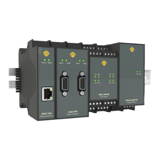
isNet Line The product family isNet Line is a modular gateway solution to inte- The system is modular and consists of an Ethernet head module grate legacy fieldbuses like HART, Profibus or FOUNDATION Fieldbus and different fieldbus expansion modules. Expansion modules are into Ethernet based fieldbus environments. - Page 6 overview PROFIBUS DP isNet DP isNet DP2 isNet DPMon PROFIBUS PA isNet DiagM PA isNet PAMon Foundation Fieldbus isNet Lite isNet FF isNet FF4 isNet FFMon HART isNet H@rt4 isNet H@rt8 isNet H@rt+AI...
-
Page 7: Dimensional Drawing
Dimensional drawing 114,5 mm 114,5 mm 114,5 mm 45,2 mm 22,5 mm 6,7 mm 6,7 mm... -
Page 8: Isnet Lite
isNet Lite The Ethernet module isNet Lite is the head module of every isNet The isNet Lite can be controlled and configured by using a web in- Line gateway solution. In combination with any of the fieldbus terface which allows diagnosis and maintenance of the main module expansion modules its purpose is to exchange process data between and its connected expansion modules (see chapter 3 “Web Interface”... - Page 9 1.2.1 Channel assignment Shield Power Status isNet Lite Ethernet Gateway...
- Page 10 1.2.2 Hardware Reset isNet Lite There may be reasons to restore firmware defaults of the isNet Lite like a failed firmware upgrade, a forgotten IP address or an IP address set to DHCP without having a DHCP server available in the network.
- Page 11 1.2.3 Technical Details Electrical data Environmental data Interface RJ 45 (Ethernet) Temperature range - 40 °C <= T <= 70 °C Controller ARM9 32Bit 400 MHz - 40 °F <= T <= 158 °F 32 MB Storage temperature - 40 °C <= T <= 85 °C Flash 256 MB...
-
Page 12: Isnet Dp
isNet DP With the isNet DP module the main module isNet Lite can be extend- is provided by a SubD9 connector (female). The modules offer all ed to work as a PROFIBUS-DP Ethernet Gateway. The main module recognized baud rates of up to 12 Mbit/s. can be enhanced with a maximum of 5 PROFIBUS modules. - Page 13 1.3.1 Technical details 1-Channel isNet DP 2-Channel isNet DP2 Connectors 1 RS-485 2 RS-485 Power consumption 2,4W 2,5W LxWxH in mm 114,5 x 22,5 x 99 114,5 x 45 x 99 Weight 140 g 250 g Temperature range 0 °C <= T <= 50°C / 32 °F <= T <= 122°F Transmission rate...
- Page 14 1.3.2 Channel assignment Channel 1 Channel 2 Ground Status Token Status Token Status Token isNet DP isNet DP2 Profi bus DP Master Profi bus DP Master...
-
Page 15: Isnet Diagm Pa
isNet DiagM PA The isNet DiagM PA module is a Profibus Master with a PA physical In combination with the isNet Lite the module can be used as a layer interface. It allows direct connection of Profibus PA field devic- gateway between Profinet and Profibus PA or as a Modbus-TCP es without the need of a DP/PA converter. - Page 16 1.4.1 Technical details 1-Channel isNet DiagM PA Connectors 1 screw terminals Power consumption 2,0W LxWxH in mm 114,5 x 45 x 99 Weight 250 g Temperature range - 40 °C <= T <= 60 °C / -40 °F <= T <= 140 °F Storage temperature - 40 °C <= T...
- Page 17 1.4.2 Channel assignment 1.4.3 Connection with a PLC PNIO PLC Bus Data PNIO Power Status isNet DiagM PA Diagnostic Master Bus Data isNet DiagM PA Diagnostic Master isNet Lite Ethernet Gateway Termination plug in the last module! Shield PROFIBUS PA devices PA - PA supply...
- Page 18 1.4.4 Hardware Installation Termination Power Status Profibus PA Bus Data Connection with an external power supply Profibus PA power supply The PA modules enable you to connect to an existing PA network via isNet DiagM PA Diagnostic Master or other isNet Lite the signal lines PA+ and PA-.
-
Page 19: Isnet H@Rt
isNet H@rt With the isNet H@rt Module the main module isNet Lite can be isNet H@rt module can be thought of as 4 (or 8) independent HART extended to work as an HART-Ethernet-Gateway. The HART-Eth- modems in a single enclosure. Each HART channel must be connect- ernet-Gateway is an up-to-date option to replace the widely used ed in parallel to the 2 wires of the control loop regardless of its po- RS485 HART multiplexer solutions, as it enables the direct connec-... - Page 20 1.5.1 Technical details 4 - Channel isNet H@rt4 8 - Channel isNet H@rt8 Connectors 4 screw type terminals 8 screw type terminals LxWxH in mm 114,5 x 22,5 x 99 114,5 x 45 x 99 Power consumption 1,2 W 1,4 W Weight 140 g 250 g...
- Page 21 1.5.2 Channel assignment 1.5.3 Connection to a slave Ch 1 Ch 5 240 Ω Ch 2 Ch 6 Slave 24 V Ch3 Ch4 Ch5 Ch6 isNet H@rt4 HART Master Ch3 Ch4 Ch3 Ch4 Ch7 Ch8 isNet H@rt4 isNet H@rt8 HART Master HART Master Master Ch 3...
- Page 22 1.5.4 Connection with a PLC Slave Ch3 Ch4 isNet H@rt4 HART Master Master Termination plug in the last module!
-
Page 23: Isnet H@Rt+Ai
isNet H@rt+AI The isNet H@rt8+AI module combines the HART master module with The measured analog values can be read by a connected PLC using 4..20mA Analog Input functionality. The module provides 8 active AI Modbus/TCP or Profinet. Due to the HART master functionality the channels, which means the module will supply 24V DC to the HART PLC has also access to the digital values of the HART instruments. - Page 24 1.6.1 Technical details 8 - Channel isNet H@rt8+AI Connectors 8 screw type terminals LxWxH in mm 114,5 x 45 x 99 Power consumption 1,8 W Weight 250 g Temperature range - 40 °C <= T <= 70 °C / - 40 °F <= T <= 158 °F Storage temperature - 40 °C <= T...
- Page 25 1.6.2 Channel assignment 1.6.3 Connection to a slave Ch 1 Ch 5 Ch 2 Ch 6 Ch5 Ch6 Ch3 Ch4 Ch7 Ch8 isNet H@rt8+AI HART Master Ch 3 Ch 7 Ch 4 Ch 8 Ch5 Ch6 Shield Ch3 Ch4 Ch7 Ch8 HART + HART - isNet H@rt8+AI...
-
Page 26: Isnet Dio
isNet DIO The isNet DIO is a Digital Input/Output expansion module for the The module does not only read or write binary logic levels, but every isNet Line. The module exists in 2 versions, one with 4 and one channel can also be configured to operate with more sophisticated with 8 I/O channels. - Page 27 1.7.1 Technical details 4-Channel isNet DIO4 8-Channel isNet DIO8 Connectors 4 screw type terminals 8 screw type terminals LxWxH in mm 114,5 x 22,5 x 99 114,5 x 45 x 99 Power consumption Weight 140 g 250 g Temperature range - 40 °C <= T <= 70 °C / - 40 °F <= T <= 158 °F...
- Page 28 1.7.2 Channel assignment 4 channel module 8 channel module IN - Ch 1 Ch 1 Ch 5 Ch 2 Ch 2 Ch 6 IN - isNet DIO4 isNet DIO8 Digital I/O Module Digital I/O Module Ch 3 Ch 3 Ch 7 Ch 4 Ch 4 Ch 8...
-
Page 29: Isnet Pamon And Dpmon
isNet PAMon and DPMon With the isNet DPMon and isNet PAMon modules the head mod- ule isNet Lite can be enhanced by diagnosis and protocol monitor functions. The modules detects and diagnoses sporadically occurring problems during data transmission on a PROFIBUS network. The modules identifies configuration problems in the transmission proto- col as well as electrical faults that cause interruptions. - Page 30 1.8.1 Technical details isNet DPMon isNet PAMon Connectors 1 RS-485 2 screw type terminals LxWxH in mm 114,5 x 22,5 x 99 114,5 x 45 x 99 Power consumption 2,5W 2,4W Weight 140 g 250 g Temperature range 0°C <= T <= 50°C / 32°...
- Page 31 1.8.2 Channel assignment PROFIBUS DPMon PROFIBUS PAMon Shield PA - Ch 1 Ch 2 3 — Channel B 5 — Ground 6 — +5V 8 — Channel A isNet DP Mon DP Monitor Module isNet PAMon PROFIBUS PA Monitor MMC Slot RS-485 MMC Slot...
-
Page 32: Isnet Ffmon
isNet FFMon With the isNet FFMon module, the main module isNet Lite can be enhanced by new diagnosis and protocol monitor functions. The modules detects and diagnoses sporadically occurring problems during data transmission on a FOUNDATION FIELDBUS network. The modules identifies configuration problems in the transmission proto- col as well as electrical faults that cause interruptions. - Page 33 1.9.1 Technical details isNet FFMon Connectors 2 Screw terminals LxWxH in mm 114,5 x 45 x 99 Power consumption 2,4W Weight 250 g Temperature range 0°C <= T <= 50°C / 32° <= T <= 122°F Transmission rate 31,25 kBit/s Driver software Windows 2000, XP, Vista, 7, 8 or 10 Hardware, isNet DTM Library, isFieldDiagnosis Setup, Pactware,...
- Page 34 1.9.2 Channel assignment Shield FF H1- FF H1+ Ch 2 Ch 1 isNet PAMon PROFIBUS PA Monitor MMC Slot...
-
Page 35: Hardware Installation
Hardware installation Safety instructions Installation notes Installation, operation and maintenance must be made by qualified personnel only and in accordance with your local and national technical regulations and safety directives. Do not repair the device yourself, but replace it with an equivalent device. Repairs may be performed by the manu- facturer only. -
Page 36: Mechanical Installation
Mechanical installation Starting from the left there is always mounted the main module is- at the last expansion module. This termination plug is not intended Net Lite. To the right of isNet Lite up to 5 expansion modules can be to connect wires. - Page 37 2.2.1 Specific conditions of use The equipment shall be installed in an enclosure that provides a degree of protection not less than IP 54 in accordance with IEC/EN 60079-15 and that have been considered to be not accessible in normal operation without the use of a tool. Transient protection shall be provided that is set at a level not exceeding 140 % of the peak rated voltage value at the supply termi- nals to the equipment.
-
Page 38: Electrical Installation
Electrical installation Before installation of the modules and wiring make sure that the system is off power. The supply voltage of 24V is only connected to the main module isNet Lite. The expansion modules are supplied via the backplane bus from the main module. -
Page 39: Web Interface
Web Interface The isNet Lite provides a web interface for startup operation, set- the pictures do not match the actual module configuration, then the tings and maintenance. The layout consists of a top area with a view isNet Lite was not able to recognise the attached modules correctly. of the actual module configuration, a menu on the left side that is In this case please check the termination plug (see ch. -
Page 40: Configuration Of The Ip Address
Configuration of the IP address The default address of the module is: 192.168.0.10 subnet mask 255.255.255.0 Use your favorite browser to go the IP Address of your isNet Lite Headstation. You should see this website. This is a overview over the current status. Click on „Network Settings“... -
Page 41: Update Of The Firmware
Update of the Firmware If a new firmware is available for your device you can flash it using the web interface. Go to the Menu Firmware and select the file you want to flash. Click the Upload button and wait until a confirmation appears that the upload was successful. -
Page 42: Password Protection
Password Protection To enable a global password protection for the isNet Lite web interface, click on the Password menu on the left. Activate the Password protection by clicking in the checkbox. Enter your pass- word and repeat it in the field below. Click Apply to confirm your settings. -
Page 43: Activating Modbus Functionality
Activating MODBUS functionality To unlock the MODBUS functionality, you need to enter a valid license code. Go to the License Key page and enter the key. After clicking Apply, the MODBUS feature will be activated. Enable the MODUBS gateway by clicking Activate MODBUS Gateway. -
Page 44: Modbus Status
MODBUS status The menu MODBUS Gate shows an overview of the MODBUS sta- tus. You can upload a FCML configuration file here. -
Page 45: Hart Over Ip
HART over IP Enable or disable HART over IP at this menu. It also shows the cur- rent status of the HART over IP functionality. -
Page 46: Fdt Configuration
FDT Configuration We also provide a CommDTM for FDT Frame Applications. To install the CommDTM you need to install the „isNet H@rt DTM Setup.exe“ from the CD-Rom. After that you have to start your FDT-Frame Application and it will update its DTM database. The FDT Frame Application PACTware is used in this manual as an example. - Page 47 The next step is to right click on the isNet Lite and select Parame- ter. You can now select the correct IP address of the isNet Lite. Just click on the Drop-Down-List as shown. The dialog will show all attached modules. If you click on „Create Child DTM“ they will be added to your project below the isNet Lite.
- Page 48 If the CommDTM could not find any isNet Lites or if the isNet Lite is offline you are able to configure it offline. You just need to click the check box „Offline Configuration“. Then enter the IP address manually and select the attached modules in the right order manually.
- Page 49 Now you can add a DeviceDTM to the isNet DTM. A dialog will show up where you can select the physical channel to which the device is connected.
-
Page 50: Isnet Lite - Profinet
isNet Lite – PROFINET The PROFINET Gateway is a combination of the Ethernet headstation isNet Lite and the proven PROFIBUSand HART-master expansion modules of the product line. The implementation of the gateway firmware was done according to the profile „Fieldbus Integration into PROFINET IO 2.0“... -
Page 51: Workflow Of The Engineering Process
Workflow of the engineering process Since the isNet PNGate is a modular gateway, there is no unique GSDML file available for this gateway. In fact the user needs to create the GSDML file before working with the engineering tool of his PLC, dependig on the actual hardware configuration and depending on all used PROFIBUS slaves in the end user applica- tion. -
Page 52: Creation Of The Gsdml File
Creation of the GSDML file With the „isNet PNGate Config tool“ the creation and configu- ration of a GSDML file is a quite simple step. The tool consists of a single, stand-alone executable file and does not need to be in- stalled on the PC. - Page 53 5.2.1 Step 1: Configuration of modules The user needs to add modules to the project to match the con- figuration with the actual hardware of isNet Line modules. Add- ing modules is possible by using the context menu on the isNet Lite picture (the Ethernet head module) or by opening the mod- ule catalog and clicking on the desired module.
- Page 54 To limit the number of PROFINET slots for better ressource usage, the user can set limits to the address range used by PROFIBUS and/or HART modules (in case of multidrop). By using the context menu (or doubleclick) on the appropriate module, the corre- sponding dialog window will open.
- Page 55 5.2.2 Step 2: Configuration of PROFIBUS slaves To make use of PROFIBUS slaves, the user needs to import the nec- essary GSD files into the GSDML project. This is possible by using the menu item “Import GSD...” of the “File” menu, by clicking on the appropriate toolbar button or by dragging the GSD files from any Explorer window of Windows into the slave list frame of the “isNet PNGate Config tool”.
- Page 56 5.2.3 Step 3: Export of the GSDML file Export of the GSDML file is done with a single mouse click on the appropriate toolbar button or by using the “Export GSDML...” menu item of the “File” menu. The following “Save as...” dialog already suggests a proper file name for the GSDML file.
-
Page 57: Integration In Simatic Manager
Integration in SIMATIC Manager After creation of the GSDML file, the user can start the engineering process in the engineering tool of his PLC. This chapter shows this process with the example of SIMATIC Manager. 5.3.1 Import of the GSDML file In the SIMATIC Manger project please open the HW Config Win- dow by double-clicking on the Hardware item. - Page 58 In the HW Config Windows please select menu item „Options -> Install GSD file...“. In the following Dialog browse to the folder on your storage medium with the GSDML file, select the GSDML and select the button „Install“.
- Page 59 After Installation of the GSDML file, the isNet PNGate will appear in the Hardware catalog with all underlying modules and sub- modules.
- Page 60 5.3.2 Setting up properties for isNet PNGate After adding the isNet PNGate into the engineering project, se- lect the menu item „Object Properties...“ from the context menu to change PNIO Device name and IP address of the PNIO device. The device name must match the device name, that is stored in the isNet Lite.
- Page 61 It is recommended to check the Update time for the is- Net PN- Gate. To do so, please select the PROFINET line in the SIMATIC manager and open the context menu. After selection of menu item „Object Properties...“ from the context menu, a dialog win- dows opens, where the Update time can be edited.
- Page 62 5.3.3 Setting up PROFIBUS To change the baud rate of a PROFIBUS segment, the Master ad- dress or any other bus parameter, please open the context menu of the channel of the PROFIBUS module and select menu item „Object Properties..“.
- Page 63 5.3.4 Adding fieldbus slaves to the engineering project In the hardware catalog, the PROFIBUS slaves and HART slaves appear as modules under the isNet PNGate. To add a fieldbus slave to the project, just drag it into a slot of the isNet PNGate. To determine the appropriate PROFINET slot, the „isNet PNGate Config tool“...
- Page 64 In the next example there is a HART slave attached to the HART module at channel 4. According to the example in chapter 5.2.3 the user needs to drag the HART slave into slot 29.
- Page 65 5.3.5 Parameterisation of PROFIBUS slaves and PROFIBUS modules If a PROFIBUS slave provide user specific parameter data, these parameters can be changed. To do so, please double-click on the module or select menu item „Object Properties...“ in the context menu of the module.
-
Page 66: Isnet Lite - Modbus
(single/dual module), PROFIBUS PA with up to 4 and HART supports up to 8 bus interfaces. For a detailed description of the Modbus functionality and map- ping tables, please see the Thorsis Technologies Modbus manual. -
Page 67: Isfielddiagnosis
Sophisticated filter and trigger possibilities restrict the data volume and allow for tailored start and stop conditions of the monitoring. For a detailed description of the Diagnosis functionality, please see the Thorsis Technologies isFieldDiagnosis manual. -
Page 68: Document History
Document History Version Date Description 05.09.18 initial version 21.11.18 new texts & images © Last changed 11. March 2019 Thorsis Technologies GmbH +49 391 544 563-1000 Oststr. 18 +49 391 544 563-9099 39114 Magdeburg info@thorsis.com Germany www.thorsis.com...
Need help?
Do you have a question about the isNet Series and is the answer not in the manual?
Questions and answers