
Related Manuals for Airgroup COOLBREEZE D095

Summary of Contents for Airgroup COOLBREEZE D095
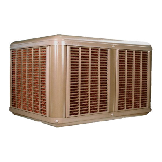
- Page 1 COOLBREEZE TECHNICAL SERVICE MANUAL INCLUDES MAXIMA INVERTER MOTOR JANUARY 2019 Models: D095 / D125 / D160 / D195 / D230 / D255 Model: D500 TWIN FAN www.airgroup.com.au www.coolbreeze.com.au...
-
Page 3: Table Of Contents
CONTENTS COOLBREEZE TECHNICAL SERVICE MANUAL PAGE Statutory & OH & S Obligations Important Product Information CoolBreeze Service Form Service Procedure - Pump MagnaSensor MS Float Solenoid Counter-weight Drain Valve Service Maintenance Kit Water Distribution Manifold Sump Powerflow Fan Fan Collet Set Motor Electrical Control Box MRU - Modular Roof Unit... -
Page 4: Statutory & Oh & S Obligations
STATUTORY AND OH&S OBLIGATIONS PLEASE READ THIS INSTRUCTION MANUAL CAREFULLY PRIOR TO COMMENCING SERVICE WORK LEGAL AND STATUTORY OBLIGATIONS Installation and servicing of CoolBreeze air conditioners must conform to: * Building rules and regulations * Electrical code * Plumbing code * Environmental Protection Authority (EPA) rules and regulations * and all applicable standards SAFETY AND O.H.&... -
Page 5: Important Product Information
ATTENTION: IMPORTANT PRODUCT INFORMATION It is the policy of AirGroup Australia to continuously review the reliability and safety functions of CoolBreeze air conditioners. In view of changes introduced in recent years, your attention is drawn to the recommendations listed below. -
Page 6: Coolbreeze Service Form
COOLBREEZE SERVICE FORM CUSTOMER DATE ADDRESS TECHNICIAN UNIT IDENTIFICATION / LOCATION UNIT MODEL CONTROLLER TYPE SERIAL NO. ELECTRICAL READING CONDITION SOLENOID PUMP FAN MOTOR FILTER PADS CABINET DRAIN VALVE NEXT SERVICE DUE COMMENTS SERVICE PROCEDURE CHECK LIST ConfIrm unit operation before commencing service Isolate Main Electrical Supply Remove Lid, Manifold, Louvres &... -
Page 7: Service Procedure
SERVICE PROCEDURE PUMP SP2380 Note: pre-2015 JRM pump (SP2127) replaced by Super Pump (SP2380) - SP2127 no longer available Check pump resistance = 40Ω / operating 240vac Run pump - visual check for vibration / correct operation Listen for abnormal sounds - damaged bearings etc Check hoses and clips for damage OLD PUMP SP2127 - NLA Remove basket and clear debris... -
Page 8: Water Distribution Manifold
SERVICE PROCEDURE WATER DISTRIBUTION MANIFOLD SP2009 Check manifold to ensure all holes are clear NOTE: poor water quality can cause scale build-up on holes Check Riser pipe for splits - replace in necessary SUMP SP1009B Twin Fan - SP1530 Remove any debris from sump including under pads etc Wipe out sump - only use mild soap &... -
Page 9: Electrical Control Box
SERVICE PROCEDURE ELECTRICAL BOX (WITH CAPACITOR COVER) SP3045 Plastic Cased Capacitor MUST be replaced with P2 Metal cased capacitor MRU - MODULAR ROOF UNIT PCB SP3000 Check for condensation and water marks Check for discoloration on PCB and components Check fuse holder - firm fit / no flash or carbon marks Check fan speed setting is correct Check all terminal connections are firm fit Ensure cables / wires are not kinked... -
Page 10: Motor Specifications - Tac Induction Motor
MOTOR SPECIFICATIONS - TAC INDUCTION MOTOR MOTOR SPECIFICATIONS 600 WATT 750 WATT 1000WATT - COLD MOTOR MOTOR MOTOR MOTOR Motor Winding Resistance ± 10% Black & White Wire (Start Winding) 6.5 Ω 5.5 Ω 4.5 Ω Brown & Blue Wire (Run Winding) 5.0 Ω... -
Page 11: Modular Roof Unit
MODULAR ROOF UNIT (MRU) - SP3000 SPEED POT ADJUST RPM Page 11... -
Page 12: Multi Unit Control System (Mucs)
MULTI UNIT CONTROL SYSTEM (MUCS) MULTI UNIT CONTROL SYSTEM [MUCS] - operate up to 99 units from 1 keypad Order one less MUCS Board than total number of units operating from one keypad. 4 units operating from one keypad - order 3 x MUCS Boards LOCAL PREVIOUS... - Page 13 FAULT FINDING - TAC INDUCTION MOTOR (not inverter motor) ELECTRICAL FAULTS FAULT CAUSE ACTION 1. NO DISPLAY AT Display illumination level set too low. Whilst in ‘OFF’ mode adjust illumination with speed > (increase) KEYPAD button. Check mains fuse, circuit breaker, unit isolation switch or MRU. 240v mains supply isolated.
- Page 14 FAULT FINDING - TAC INDUCTION MOTOR (not inverter motor) WATER FAULTS FAULT CAUSE ACTION 8. WATER NOT Isolation tap closed or filter blocked. Open tap and/or clean filter. ENTERING UNIT Solenoid time delay active. Wait 1 min for drain valve to close & delay to end. Select ‘COOL’...
-
Page 15: Dip Switch Speed Setting Chart
MAXIMA INVERTER MOTOR ECRU DIAGRAM DIP SWITCH SPEED SETTING CHART MODEL DIP SWITCH MD095 Grey / Green OFF OFF MD125/C125 Grey / Green OFF OFF OFF OFF OFF OFF OFF MD160/C160 Grey / Grey OFF OFF OFF OFF OFF MD195/C205 Black Powerflow OFF OFF OFF OFF OFF... -
Page 16: Maxima Inverter Motor
FAULT FINDING - MAXIMA INVERTER MOTOR ELECTRICAL FAULTS FAULT CAUSE ACTION 1. NO DISPLAY AT 1.1 Display illumination level set too low. Whilst in ‘OFF’ mode adjust illumination with speed > (increase) KEYPAD button. 1.2 240v mains supply isolated. Check mains fuse, circuit breaker, unit isolation switch and red LED on ECRU. - Page 17 FAULT FINDING - MAXIMA INVERTER MOTOR WATER FAULTS ATTENTION: Be advised that the MS control unit does NOT switch power to the pump and solenoid when removed from the ECRU. FAULT CAUSE ACTION 6. WATER NOT Isolation tap closed or filter blocked Open tap and/or clean filter.
- Page 18 GENERAL SPECIFICATIONS - TAC INDUCTION MOTOR D095 D125 D160 D195 D230 D255 D500 MODEL Motor Voltage (50 Hz) 220-240 SINGLE PHASE Thermal Protection: 1x Auto Reset and 1x Manual Reset Insulation “B” Class “B” Class “F” Class “F” Class “F” Class “F”...
-
Page 19: Maxima Inverter Models D230 - D255
GENERAL SPECIFICATIONS - MAXIMA INVERTER MOTOR D230 D255 MODEL Motor Frequency 50 / 60 Hz Current Limit Protection Insulation “B” Class AC 220v - 240v SINGLE PHASE Power Supply 1060 Watts Model HFM017 0.2 / 3.7 0.2 / 4.3 Amp Draw @240V - low/high RPM - 1230 1330... - Page 20 EXPLODED VIEW - D series 095 - 255 BOLT x 4 MANIFOLD RISER PIPE MOTOR RING CNR POST COLLET MOTOR LOUVRE LOUVRE CNR POST DRAIN PUMP FLOAT ELBOW COVER SOLENOID SWITCH CAPACITOR CNR POST SUMP LOUVRE BOLT x 4 LOUVRE CNR POST Page 20...
-
Page 21: D500 Twin Fan Model
EXPLODED VIEW - D500 TWIN FAN UNIT BOLT x 6 MANIFOLD CNR POST RISER PIPE RISER PIPE LOUVRE CENTRE POST COVER FAN x2 MOTOR RING LOUVRE SWITCH LOUVRE CAPACITOR MOTOR RING MRU BOX COLLET ELBOW SOLENOID MOTOR COVER PUMP PUMP CNR POST SWITCH DRAIN... -
Page 22: D500 Twin Fan - Identification Information
D500 TWIN FAN - INFORMATION When fault finding on the D500 Twin Fan model, first identify the Primary and Secondary Modular Roof Unit (MRU). Open each Electrical Control Box: The Primary MRU Box has an additional circuit board inside > The Primary MRU is on the side of the unit with the Counter-weight Drain Valve fitted. - Page 24 Head Office & Manufacturing AirGroup Australia 28 Division Street Welshpool WA 6106 Phone: 08 9350 2200 Fax : 08 9451 3077 AUSTRALIA FM392/0119 Email: service@airgroup.com.au...
Need help?
Do you have a question about the COOLBREEZE D095 and is the answer not in the manual?
Questions and answers
How do u link 2 veri boards to a cascade board