Table of Contents
Advertisement
Quick Links
Advertisement
Table of Contents

Related Manuals for P&E Microcomputer Systems Cyclone LC Series

Summary of Contents for P&E Microcomputer Systems Cyclone LC Series
- Page 1 Cyclone LC Programmers User Manual...
- Page 2 Purchase Agreement P&E Microcomputer Systems, Inc. reserves the right to make changes without further notice to any products herein to improve reliability, function, or design. P&E Microcomputer Systems, Inc. does not assume any liability arising out of the application or use of any product or circuit described herein. This software and accompanying documentation are protected by United States Copyright law and also by International Treaty provisions.
-
Page 3: Table Of Contents
INTRODUCTION............................9 Cyclone Feature Comparison..........................9 Advanced Feature Licenses..........................9 1.2.1 ProCryption Security License ............................9 1.2.2 Cyclone Control Suite Advanced Features License ....................10 1.2.3 SDHC Port Activation License.............................10 QUICK START GUIDE FOR SAP OPERATION ..................11 Installing The Cyclone Software........................11 Setting Up The Cyclone Hardware........................11 Creating A Stand-Alone Programming Image ....................13 2.3.1 Advanced Features ..............................16... - Page 4 3.18.8 PORT H: 20-Pin Debug Connector (Kinetis, S32 (ARM), other PEmicro-Supported ARM devices) ......32 3.19 Ribbon Cable..............................33 TARGET POWER MANAGEMENT ......................34 Cyclone Configuration ...........................34 Cyclone Setup ...............................36 4.2.1 Independently Powered Target ...........................36 4.2.2 Power provided by the Cyclone to the debug cable ....................36 4.2.3 External Power passed through the Cyclone and out 2.5 mm barrel port..............37 4.2.4...
- Page 5 Operation Via Start Button ..........................63 7.1.1 LED Indicators................................63 7.1.2 Procedure via Start Button / LEDs ..........................63 7.1.3 Example ..................................63 Operation Via LCD Touchscreen Menu ......................64 Home Screen ..............................64 7.3.1 Icons....................................64 7.3.2 Configurable Display Area............................64 Status Window ..............................65 7.4.1 Error Information Icon..............................65 7.4.2 AUX Button (Appears If Configured) ...........................65 7.4.3...
- Page 6 9.2.5 Sample Batch File ..............................108 CSAP Error Returns ............................108 ETHERNET CONFIGURATION......................111 10.1 Network Architectures ..........................111 10.2 Network Parameters............................111 10.3 Internet Protocol ............................112 10.4 Connecting The Cyclone Device .........................112 10.4.1 Connecting the Cyclone to the PC over a network....................112 10.4.2 Connecting Cyclone-to-PC via an Ethernet cable .....................113 10.5 Cyclone IP Setup Via LCD Menu ........................113...
- Page 7 12.5 Creating A SAP Image With Multiple Serial Numbers.................127 12.6 Shared Serial Numbers ..........................128 12.6.1 Example ..................................128 CYCLONE LICENSE INSTALLATION ....................133 13.1 How to Install Your License.........................133 TROUBLESHOOTING ..........................138 14.1 My Cyclone Is Non-Responsive, Is There A Way To Re-Activate It?............138 14.1.1 What Is Bootloader Mode?............................138 14.1.2...
- Page 8 17.6 Debug Ports - CYCLONE-LC-UNIV ......................149 17.7 International Shipping..........................149 17.8 Compliances/Standards ..........................149...
-
Page 9: Introduction
INTRODUCTION PEmicro's Cyclone LC production programmers are powerful, fast, and feature rich in-circuit programming solutions. PEmicro offers two models which have the same feature set and only vary by the devices supported. Part# CYCLONE-LC-ARM supports a wide variety of ARM Cortex devices. Part# CYCLONE-LC-UNIV supports those ARM Cortex devices as well as the following NXP device families: Kinetis, LPC, S32, MPC55xx-57xx), MPC5xx/8xx, DSC, S12Z, RS08, S08, HC08, HC(S)12(X), ColdFire, and STMicroelectronics’... -
Page 10: Cyclone Control Suite Advanced Features License
1. RSA/AES encryption of programming images Users create unique ImageKeys which are used to encrypt their programming images. SAP images encrypted in this way can only be loaded onto a Cyclone or programmed with a Cyclone if that Cyclone has been provisioned with the identical ImageKey. 2. -
Page 11: Quick Start Guide For Sap Operation
QUICK START GUIDE FOR SAP OPERATION This guide will allow the user to set up and program a simple Stand-Alone Programming (SAP) image with the Cyclone by completing the following steps. • Installing the Cyclone software • Setting up the Cyclone hardware •... - Page 12 If power is provided via the Cyclone, the user may need to configure the programming image accordingly. Image creation and configuration is discussed in Section 2.3 - Creating A Stand-Alone Programming Image. For more information on the various power configurations, the user should refer to their Cyclone’s User Manual.
-
Page 13: Creating A Stand-Alone Programming Image
Creating A Stand-Alone Programming Image A stand-alone programming (SAP) image is the result of pre-processing the programming algorithms, data to be programmed, programming options, and scripted programming commands. These are combined into a single encrypted file. This SAP image can then be loaded onto the Cyclone and used to program, without need for the Cyclone to be connected to a PC. - Page 14 The following instructions walk the user through each of these steps: Step 1. Run Cyclone Image Creation Utility CreateImage.exe is in the “ImageCreation” folder, in the location where the Cyclone software was installed. For an in-depth description of the Cyclone Image Creation Utility, see Section 6.1 - Cyclone Image Creation Utility.
- Page 15 Step 4. Adding Basic Programming Commands The user should then add other basic programming commands, using the list of commands on the left side of the Programming Sequence area. The arrow and buttons allow the user to add, remove, and re-sequence the commands, in the box on the right.
-
Page 16: Advanced Features
These settings can be made using the corresponding areas of the Cyclone Image Creation Utility. Step 6. Save SAP image to Cyclone The user should then save the SAP image onto the Cyclone by clicking the button to save to “Cyclone Only”... - Page 17 able in the Cyclone’s User manual or at: http://www.pemicro.com/blog/ index.cfm?post_id=142 3. SDK - The SDK is a software library that is used in conjunction with the user’s own code. The user writes a customer application that uses this library of functions to launch pro- gramming.
-
Page 18: Cyclone Lc Hardware
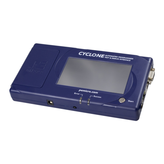
CYCLONE LC HARDWARE The following is an overview of the features and interfaces of Cyclone LC programmers. Many of these interfaces are labeled on the underside of the plastic case. Figure 3-1: Cyclone LC Top View Touchscreen LCD The LCD Touchscreen displays information about the Cyclone’s configuration and the programming process, and also allows the user to navigate the Cyclone’s menus. -
Page 19: Cyclone System Power
Figure 3-2: Cyclone LC Right Side View Cyclone System Power The Cyclone LC programmer requires a regulated 6V DC Center Positive power supply with 2.5/ 5.5mm female plug. Cyclones derive power from the Power Jack located on the right end of the unit. -
Page 20: Power Connectors
Figure 3-3: Cyclone LC Front Side View 3.10 Power Connectors The Cyclone LC programmers provide a Target Power Supply Input Jack and a Target Power Supply Output Jack with 2.5/5.5 mm Pin Diameter. The power jacks are connected or disconnected by two electromechanical relays. When connected, the Center Pin of the Target Power Supply Input Jack is connected to the Center Pin of the Target Power Supply Output Jack. -
Page 21: Optional Oscillator (Mon08 Only)
encountering any difficulty while trying to use an SDHC card. 3.13 Optional Oscillator (MON08 Only) Cyclone LC programmers with MON08 support (PEmicro Part# CYCLONE-LC-UNIV only) provide a software configurable 9.8304MHz or 4.9152 MHz oscillator clock signal to Pin 13 of the MON08 Connector. - Page 22 Figure 3-5: Target Headers & Power Jumpers (CYCLONE-LC-UNIV vs.CYCLONE-LC-ARM) Mechanical drawings are shown below whose dimensions are representative of the pin size and spacing of these headers. Note: The number of pins depicted in the mechanical drawings may differ from the Cyclone headers; the drawings are provided simply to demonstrate pin size and spacing.
-
Page 23: Target Headers For Part# Cyclone-Lc-Arm
Figure 3-7: Mini 10-Pin and Mini 20-Pin Keyed Header Dimensions 3.17 Target Headers For Part# CYCLONE-LC-ARM PEmicro Part# CYCLONE-LC-ARM features 3 ports labeled A-C. 3.17.1 PORT A: 10-Pin Keyed Mini Connector (Kinetis, S32 (ARM), other PEmicro-Supported ARM devices) 3.17.1.1 JTAG Pin Assignments The Cyclone provides a keyed 10-pin 0.050-inch pitch double row connector for ARM targets. -
Page 24: Port B: 20-Pin Keyed Mini Connector (Kinetis, S32 (Arm), Other Pemicro-Supported Arm Devices)
3.17.1.2.1 High-Performance Communications (FX ONLY) If high-performance options are available for the selected device they will appear in the “Shift Frequency in MHz” drop-down. Cyclone programmers are capable of high-performance communications when using certain ARM Cortex targets in SWD mode. Note: Cyclone LC programmers cannot currently take advantage of high-performance options, although the frequencies appear in the display. -
Page 25: Port C: 20-Pin Debug Connector (Kinetis, S32 (Arm), Other Pemicro-Supported Arm Devices)
SWD Mode is selected from the “Communication Mode” drop-down box in the Cyclone Image Creation Utility: Figure 3-10: Communications Mode Selection 3.17.2.2.1 High-Performance Communications (FX ONLY) If high-performance options are available for the selected device they will appear in the “Shift Frequency in M Hz”... -
Page 26: Target Headers For Part# Cyclone-Lc-Univ
PIN 7 - TMS/SWDIO GND - PIN 8 PIN 9 - TCK/SWCLK GND - PIN 10 PIN 11 - NC* GND - PIN 12 PIN 13 - NC* GND - PIN 14 PIN 15 - RESET GND - PIN 16 PIN 17 - NC* GND - PIN 18 PIN 19 - NC*... -
Page 27: Port B: 20-Pin Keyed Mini Connector (Kinetis, S32 (Arm), Other Pemicro-Supported Arm Devices)
3.18.1.2 SWD Mode Pin Assignments Cyclone LC programmers also support SWD Mode. This replaces the JTAG connection with a clock and single bi-directional data pin. 10-Pin Keyed Mini Connector SWD Mode Pin Assignments PIN 1 - TVCC TMS/SWDIO - PIN 2 PIN 3 - GND TCK/SWCLK - PIN 4 PIN 5 - GND... -
Page 28: Port C: 14-Pin Debug Connector (Mpc55Xx-57Xx, Spc5, Dsc, S32 (Power))
3.18.2.2 SWD Mode Pin Assignments Cyclone LC programmers also support SWD Mode. This replaces the JTAG connection with a clock and single bi-directional data pin. 20-Pin Keyed Mini Connector SWD Mode Pin Assignments PIN 1 - TVCC TMS/SWDIO - PIN 2 PIN 3 - GND TCK/SWCLK - PIN 4 PIN 5 - GND... -
Page 29: Port D: 26-Pin Debug Connector (Coldfire V2/3/4)
RESET VDDE7 JCOMP DSC Pinout NC/KEY RESET TRST *The pin is reserved for internal use within the PEmicro interface. 3.18.3.1 BERG14-to-MICTOR38 Optional Connector PEmicro offers a 14-pin BERG to 38-pin MICTOR adapter, sold separately, that may be used on Port C of the Cyclone LC. The PEmicro part number is BERG14-TO-MICTOR38. Figure 3-18: BERG14-TO-MICTOR38 Adapter (Sold Separately) 3.18.4 PORT D: 26-Pin Debug Connector (ColdFire V2/3/4) -
Page 30: Port E: 16-Pin Debug Connector (Mon08)
DDATA0 *The pin is reserved for internal use within the PEmicro interface. The ColdFire adapter for Synchronous targets and ribbon cable for Asynchronous targets is pictured below: Figure 3-19: ColdFire Adapter (part# CABLE_CF_ADAPTER (Rev. B), for synchronous ColdFire targets, sold separately) Figure 3-20: ColdFire Ribbon Cable (for asynchronous ColdFire targets, included with Cyclone) 3.18.5 PORT E: 16-Pin Debug Connector (MON08) -
Page 31: Port F: 6-Pin Debug Connector (Rs08, Hcs08, Hc(S)12(X), S12Z, Coldfire +/V1, Stm8 W/ Adapter)
*The pin is reserved for internal use within the PEmicro interface. **The pin is reserved for internal use within the PEmicro interface only when using an MR8 target. 3.18.6 PORT F: 6-Pin Debug Connector (RS08, HCS08, HC(S)12(X), S12Z, ColdFire +/V1, STM8 w/ adapter) The Cyclone provides a standard 6-pin 0.100-inch pitch dual row 0.025-inch square header for ColdFire V1, S12Z, 68(S)12(X), 68HCS08, RS08, and STMicroelectronics’... -
Page 32: Port G: 10-Pin Debug Connector (Power Mpc5Xx/8Xx)
3.18.7 PORT G: 10-Pin Debug Connector (Power MPC5xx/8xx) The Cyclone provides a standard 10-pin 0.100-inch pitch dual row 0.025-inch square header for Power MPC5xx/8xx BDM targets. The location of the this header is indicated as PORT G in Figure 3-5. Power MPC5xx/8xx BDM Pinout SRESET# DSCLK... -
Page 33: Ribbon Cable
Figure 3-22: Communications Mode Selection 3.18.8.2.1 High-Performance Communications (FX ONLY) If high-performance options are available for the selected device they will appear in the “Shift Frequency in MHz” drop-down. Cyclone programmers are capable of high-performance communications when using certain ARM Cortex targets in SWD mode. Note: Cyclone LC programmers cannot currently take advantage of high-performance options, although the frequencies appear in the display. -
Page 34: Target Power Management
TARGET POWER MANAGEMENT Different target devices may require different power schemes which depend on the design of the target board, target voltages, and even the device architecture. PEmicro has designed the Cyclone LC to be capable of powering a target before, during, and after programming. Power can be sourced at many voltage levels from the Cyclone itself, or sourced by an external power supply and switched by the Cyclone. - Page 35 Note: If these jumpers are not set correctly, the Cyclone will not function as intended. Target is powered independently Power provided externally (center +) and managed by Cyclone, power out to debug ribbon cable. Power provided externally (center +) and managed by Cyclone, power out to 2.5 mm output jack (center +) Power provided by Cyclone, power out to...
-
Page 36: Cyclone Setup
After the basic hardware setup, target power and voltage settings are also set in the creation of a SAP (stand-alone programming) image. At a minimum the SAP image contains all the commands to Erase, Program, and Verify a programming image. More sophisticated power selections in the SAP image can control the relays, target voltage, delays, and power down after SAP operations, as shown in the selection dialog. -
Page 37: External Power Passed Through The Cyclone And Out 2.5 Mm Barrel Port
Figure 4-6: Power Provided by the Cyclone to the Debug Cable 4.2.3 External Power passed through the Cyclone and out 2.5 mm barrel port It is also possible to provide external power, passed through the Cyclone power relays, and back out to be available to power the target board externally. -
Page 38: Power Provided By The Cyclone And Out 2.5 Mm Barrel Port
Figure 4-8: External Power Passed Through the Cyclone to the Debug Cable 4.2.5 Power provided by the Cyclone and out 2.5 mm barrel port In a slightly different scenario, the user may wish to have the Cyclone provide power, but power the target via an external connector on the target. -
Page 39: Touchscreen Lcd Menu
TOUCHSCREEN LCD MENU This chapter describes the Cyclone’s touchscreen LCD menu. Figure 5-1 shows an overview of the menu structure. Note: This menu will change as features are added to the Cyclone LC, so if your menu does not match what is displayed here, please check PEmicro’s website, www.pemicro.com, for a user manual containing the latest LCD Menu operations information. -
Page 40: Status Window
10. Status Window and Main Menu button (always shown). 11. Programming count & limit 5.1.3 Status Window The status window appears in the lower left corner of the home screen and displays the results of programming operations. 5.1.4 Error Information Icon When the Cyclone experiences an error during programming operations, the Info icon will appear to the left of the Menu button (or AUX button, if configured). - Page 41 Figure 5-2: Main Menu Structure User Manual For Cyclone LC Programmers...
-
Page 42: Select Programming Image
5.2.1 Select Programming Image Displays a list of the available programming images so that the user may select one for programming. Images in the Cyclone’s internal memory are preceded by the designation “IN” and numbered sequentially, i.e., IN1: first image name, IN2: second image name. If the SDHC port of the Cyclone is activated and contains a memory card (and the SDHC License Activation is installed), any programming images that reside on the SD card will be preceded by the designation “EX”... - Page 43 5.2.2.1.6 Launch Image Programming Launches the selected programming image. Replaces the hardware Start Button. 5.2.2.2 Set Image Validation Allows the user to choose between two validation settings: 1) validate the image each time the Start button is pressed, or 2) do not validate the image. 5.2.2.3 Serial Numbers Displays the serial number information associated with the currently selected programming image.
-
Page 44: Configure Cyclone Settings
bottom to proceed to the next serial file (if any). Figure 5-6: Serial Number View With Older Serial Files (CS IDs #1 & #2) 5.2.2.4 Show Image Restriction Stats (Requires FX or ProCryption Security License Activation) Displays current statistics, if any, for Image Programmed Count & Maximum Allowed, Errors Logged &... - Page 45 certain that the Cyclone is not set to Dynamic IP mode. Edit IP Numbers allows the user to set an IP number for the Cyclone. The current IP number is displayed on the second line. Tap a number to edit and use the touchscreen keyboard to set the new number.
- Page 46 5.2.3.3.3 Set Date Formatting Allows you to select how the date is displayed. The options are: 1. YYYY-MM-DD 2. MM-DD-YYYY 3. DD-MM-YYYY 4. MM/DD/YYYY 5.2.3.3.4 Set Time Formatting Allows you to select how the time is displayed. The options are: 1.
-
Page 47: Status
5.2.3.5.4 Configure Home Screen This menu allows you to choose what information to display on Lines 2-8 of the home screen. Available elements to display consist if information such as: the current IP address, the Cyclone name, the number of images, etc. In this way the user can customize the display to provide the information that they find most useful. -
Page 48: Creating And Managing Programming Images
CREATING AND MANAGING PROGRAMMING IMAGES The Cyclone Image Creation Utility is used to create programming images which may be loaded into the Cyclone. The user creates programming images based on data sets to be programmed and programming instructions which are all self contained. The next step is to download these programming images to the Cyclone via the GUI, Console, or SDK. -
Page 49: Specify Cpu Manufacturer
Figure 6-1: Cyclone Image Creation Utility 6.1.1 Specify CPU Manufacturer The user should select the manufacturer of their target device from the drop-down list. Cyclone LC programmers support ARM Cortex devices from several manufacturers, including NXP’s Kinetis and LPC devices. For a complete index of PEmicro-supported ARM Cortex devices, please view pemicro.com/arm. - Page 50 Figure 6-2: Specify CPU Manufacturer 6.1.1.1 ARM-Based Devices If the user chooses “ARM Based (All Manufacturers)” they should then select their specific device. A recently used device can be selected from the Device drop-down box on the left (see Section 6.1.1.3 - Device Box).
-
Page 51: Security Settings - Qorivva (Mpc55Xx-57Xx) Only
Figure 6-4: Specify Target Architecture (NXP) Figure 6-5: Specify Target Architecture (STMicroelectronics) Note: The user can still select an ARM-based device when using the NXP or STMicroelectronics manufacturer selections. 6.1.1.3 Device Box The Device box can be used to choose from any devices that have recently been selected. Figure 6-6: Device Drop-Down - Select From Recently Chosen Devices 6.1.2 Security Settings - Qorivva (MPC55xx-57xx) Only... - Page 52 Figure 6-8: Specify Programming Sequence There are two ways to create the programming sequence. 6.1.3.1 Manual Selection The user can individually specify the algorithm and the object code and then add commands. To specify the programming algorithm for the target, double-click on the Choose Algorithm (CM) function in the left panel.
- Page 53 Figure 6-11: Specify Object File To Load Next, the user would add additional programming functions to complete the programming script by selecting programming operation commands from the Programming Sequence area. See Section 6.1.4 - Programming Operations for a description of these commands. The commands can added by double-clicking them, or by selecting them and using the arrow (->).
-
Page 54: Programming Operations
programming commands. The Remove From List button can be used to remove a selected command from the right panel. The user can also simply hit the Delete button on their keyboard when the command is selected in the programing sequence. 6.1.3.4 Programming Sequence Complete Once the programming sequence is complete, the programming image can be saved to a disk or... - Page 55 6.1.4.7 Program Words Prompts for a starting address, which must be in the module. You are then asked to enter, in hexadecimal, a word to be programmed into the current location. Clicking the OK button will automatically advance to the next data word location. 6.1.4.8 Program Module This command will program the selected S-record file into EEPROM/flash.
-
Page 56: Communication Mode And Rate Settings
6.1.4.13 Program Serial Number This command becomes available once a programming algorithm is selected. It will instruct the Cyclone to program the serial number to the target once executed. As with other commands, the serial number will not be programmed until the SAP operations are carried out. Note: 6.1.5 Communication Mode and Rate Settings... - Page 57 6.1.8.1.1 Creating an ImageKey If an ImageKey has not been created or a new ImageKey is required, the user should select the “Image Encryption” combo-box in the Cyclone Image Creation Utility and choose the “Create Image Encryption Key...” option. Figure 6-17: Create Image Encryption Key - Drop Box This will pop up a box asking for a descriptive ImageKey Name (this name will be used for display in many dialogs): Figure 6-18: Create ImageKey...
- Page 58 By default, the ImageKey will stay selected in the Image Creation Utility. If a different ImageKey is required for encryption, or the user does not wish to encrypt their SAP image, the corresponding change may easily be selected using the drop-down box. 6.1.8.1.2 Encrypting A SAP Image To create an encrypted programming image, the user sets up their parameters in the Cyclone Image Creation Utility as usual, and then simply selects the desired ImageKey in the "Image...
-
Page 59: Fx Exclusive Features
corresponding programming image when the date is on or between the dates specified. The Cyclone has an onboard battery and clock which keeps a clock running even when power to the Cyclone is removed. This clock date is the one used for comparison to the UTD Date specified in the image. -
Page 60: Store Image To Disk
In the case of a Cyclone present on a different network (i.e., not displayed automatically in the drop-down list), the user may specify its IP address by using the Specify Cyclone checkbox and typing the identifier of the Cyclone. Click on "Connect" to access the specified Cyclone. A click on the "Apply Changes" button will then store the image on the selected Cyclone. -
Page 61: Delete Images From Internal/External Memory
Figure 6-24: Manage Images Utility Upon opening a selected Cyclone in the Cyclone Control GUI, the user is provided in the first tab with a list of the images currently on the unit’s internal memory which are marked with a Storage Area label of "Internal". - Page 62 to update the Cyclone accordingly. No actual updates will occur to the Cyclone’s internal/external memory or installed SD card until the user selects “Apply Changes. Note: Any SAP images that are already stored on older Cyclone models such as the Cyclone PRO, MAX, Renesas, STMicro, or Cyclone LC ARM - Rev.
-
Page 63: Cyclone Programmer Manual Control
CYCLONE PROGRAMMER MANUAL CONTROL The Cyclone LC must be configured before it can serve as a Stand-Alone Programmer. The user may manually control the Cyclone via the LCD touchscreen menu and/or the Start button, or via PC software. See CHAPTER 8 - CYCLONE PROGRAMMER AUTOMATED CONTROL (CYCLONE CONTROL SUITE) for information on how to use the Cyclone Control Suite to configure, control, and automate Cyclone operations. -
Page 64: Operation Via Lcd Touchscreen Menu
Operation Via LCD Touchscreen Menu Once the Cyclone LC is configured for stand-alone programming it may be operated by making selections from the touchscreen LCD menu. This section describes the menu functions that allow the user to easily execute stand-alone programming functions using the touchscreen LCD. Home Screen The home screen appears when the Cyclone is powered on, or when the Home button... -
Page 65: Status Window
Status Window The status window appears in the lower left corner of the home screen and displays the results of programming operations. 7.4.1 Error Information Icon When the Cyclone experiences an error during programming operations, the Info icon will appear to the left of the Menu button (or AUX button, if configured). - Page 66 7.4.3.1.1 Launch Programming This allows the user to execute the programming function. The Cyclone will program the target device, if able, using the currently selected programming image. This is functionally equivalent to pressing the Start button. 7.4.3.1.2 Verify Data In Target Performs a verify function on the data that has been programmed into the target device.
- Page 67 Figure 7-4: Increase or Decrease Serial Number The adjustment buttons will display “Increase Not Allowed” and “Decrease Not Allowed” if the image/algorithm/CS file that the user has selected does not allow for this operation. Note: Unlike PEmicro’s current serial files, earlier “legacy” serial files are specific to one programming image, When viewing Serial Number info for an image that references one or more legacy serial files, the Cyclone will not show links to the serial files but will instead display serial number info for the first serial file.
-
Page 68: Cyclone Programmer Automated Control (Cyclone Control Suite)
CYCLONE PROGRAMMER AUTOMATED CONTROL (CYCLONE CONTROL SUITE) Users who wish to control, configure, and automate one or more Cyclone units have several options available. This chapter presents a brief overview of those options along with some additional information about each. Overview Of Cyclone Control Suite The Cyclone Control Suite is a new generation of automated control software developed to support PC based control of the popular Cyclone and Cyclone FX stand-alone programmers. -
Page 69: Pemicro Compatible Hardware
• Read Image and target Properties and Status The GUI application provides the following Advanced features for all Cyclones: • Add/Remove/Update many images in the Cyclone • Remote Display Access and the ability to “touch” the screen These features require an Advanced license only when using the SDK or Console (see below). The SDK and Console application provide the following Advanced features for all Cyclone FX units and any Cyclone upgraded with a resident Cyclone Control Advanced Automation License: •... -
Page 70: Backwards Compatibility With Classic Cyclone Control Api
The sample applications come with build scripts defined for ease of use. Simply run the scripts and you should be able to build the sample application without any modifications. The callable interface routines are defined in: INSTALLDIR\cycloneControl\controlsdk\examples\pascal\cyclone_control_api.pas INSTALLDIR\cycloneControl\controlsdk\examples\c\cyclone_control_api.h 8.2.2 Backwards Compatibility With Classic Cyclone Control API The “CycloneControlSDK.dll”... - Page 71 MSVC# 2017 Projects INSTALLDIR\cycloneControl\controlsdk\examples\msvcsharp\visual_sap_control\cyclone_control _api.cs NI LabVIEW 2018 Projects INSTALLDIR\cyclone\cycloneControl\controlsdk\examples\labview2018\user.lib\CycloneControlS DK\CycloneControlSDK.lvlib INSTALLDIR\cyclone\cycloneControl\controlsdk\examples\labview2018\user.lib\CycloneControlS DK\VIs\*.vi The pre-built VIs that we provide include modifications for error handling using error clusters. Please visit our blog post “Automated Flash Programming with LabVIEW” for more information on how to develop your own LabVIEW project.
- Page 72 function will be called once for each Cyclone. 8.2.3.4 Finalization Before closing the application, it is recommended that the session with the PEmicro hardware be terminated and the DLL unloaded from memory. These calls should always be made before the application closes: disconnectFromAllCyclones( );...
-
Page 73: Application Programming Interface (Api)
“checkCycloneExecutionStatus” call. A result of 0 will be returned even if an error has occurred or if communication with the Cyclone is lost. c. Retrieve the error code from the Cyclone unit to determine if the programming was successful. 8.2.3.7 External Memory Storage Support Some Cyclones support external memory storage. - Page 74 functions available in the library. This routine must be called before any of the other routines can be called. @returnvalue True if the load was successful, false otherwise. 8.2.4.2.2 unloadLibrary void unloadLibrary(void); This function unloads the DLL loaded with loadLibrary( ). This call should be made before the application starts to unload itself.
- Page 75 Specifies the property of the Cyclone to return. The possible values are: @parameter • CycloneInformationation_IP_Address informationType • CycloneInformation_Name • CycloneInformation_Generic_port_number A pointer to a null-terminated string containing the property value of @returnvalue the specified Cyclone. 8.2.4.3 Cyclone Connecting / Disconnecting Calls 8.2.4.3.1 connectToCyclone uint32_t connectToCyclone(char *nameIpOrPortIdentifier) ;...
- Page 76 A null terminated string containing one or more Cyclone identifiers (name, IP address, or port number) delimited by commas. Example: USB1,209.1.10.2,Orion,COM1 If identifying by IP address, the string should be in the format of xxx.xxx.xxx.xxx, where xxx = @parameter nameIpOrPortIdentifierArray 0…255.
- Page 77 A Cyclone may have several independent programming images in its non-volatile internal or external memory. A programming image contains the programming algorithms, binary data, and programming sequence. This function instructs the Cyclone to start execution of an image. After invoking this call, the “checkCycloneExecutionStatus” function is used to poll the Cyclone until completion.
- Page 78 Checks to see if the Cyclone has completed a programming operation started with either the “startImageExecution” or “startDynamicDataProgram” functions. After this function returns with completed value, “getLastErrorCode” should be called to determine the programming result. A result of 0 will be returned even if a programming error has occurred or if communication with the Cyclone is lost.
- Page 79 @returnvalue The error code of the DLL or Cyclone 8.2.4.4.7 getLastErrorAddr uint32_t getLastErrorAddr(uint32_t cycloneHandle); If the “getErrorCode” function returns a non-zero value (indicating an error has occurred), this routine can be used to query the address where the error occurred. The handle of the Cyclone from which to request the error @parameter cycloneHandle address.
- Page 80 Used to select which image stored on the Cyclone to read the description from. The valid range of this parameter is from 1 to the total number of images in the Cyclone with the count starting from internal memory and @parameter imageId then external memory.
- Page 81 latest images on a server). The handle of the Cyclone that will have its images @parameter cycloneHandle erased This parameter selects between Cyclone internal @parameter selectedMediaType Flash (selectedMediaType = 1) or external memory (selectedMediaType =2). True if the erasure was successful @returnvalue False otherwise 8.2.4.5.4 eraseCycloneImage...
- Page 82 Set to True if you want the image to overwrite any existing images with the same description @parameter replaceImageOfSameDescription Set to False if you do not want the image to overwrite any existing images with the same description. An error will occur. A pointer to a null-terminated character @parameter aFile string which contains the full path to the...
- Page 83 8.2.4.5.8 setPropertyValue bool setPropertyValue(uint32_t cycloneHandle, uint32_t resourceOrImageId, char * categoryName, char *propertyName, char * newValue); This function changes the property of the Cyclone to the value specified. Only certain properties can be changed using this call. This function will return false if the property was not changed. Refer to the header file for a list of valid category and property names.
- Page 84 This function reads the firmware version of the selected Cyclone. @parameter cycloneHandle The handle of the Cyclone of which to read the firmware version. Returns a pointer to a null-terminated character string containing @returnvalue the firmware version. 8.2.4.6.2 cycloneSpecialFeatures bool cycloneSpecialFeatures(uint32_t featureNum, bool setFeature, uint32_t paramValue1, uint32_t paramValue2, uint32_t paramValue3, void *paramReference1, void *paramReference2);...
- Page 85 A pointer to a null-terminated character string which @parameter paramReference2 contains the full path to the specified SAP file. True if the CRC32 was read @returnvalue False otherwise @parameter featureNum CYCLONE_GET_IMAGE_SETTINGS_FROM_FILE Indicates whether the image file has been decoded. @parameter setFeature If previous operations has already decoded the file, then set it to true.
- Page 86 CYCLONE_GET_IMAGE_SCRIPT_FILE_FROM_FI @parameter featureNum Indicates whether the image file has been decoded. If @parameter setFeature previous operations has already decoded the file, then set it to true. Otherwise set it to false. @parameter paramValue1 Ignored, set it to 0. @parameter paramValue2 Ignored, set it to 0.
-
Page 87: Cyclone Control Console
@parameter paramValue3 Ignored, set it to 0. A pointer to an array containing the security code @parameter paramReference1 bytes. A pointer to a null-terminated character string @parameter paramReference2 containing the security type string (such as 'MON08', 'RENESAS', 'PPCNEXUS'). True if the security code was set @returnvalue False otherwise Cyclone Control Console... - Page 88 -putdynamicdata=[cyclone number],[address],[data] ONLY SUPPORTED BY CYCLONE FX OR THE CYCLONE CONTROL SUITE ADVANCED LICENSE. Performs programming of dynamic data with the selected Cyclone unit. [cyclone number] is the index of the connected Cyclone in the order in which it was entered. [address] is the starting memory address. [data] are the bytes of data to be programmed.
-
Page 89: Examples
-firmwareupdate=[firmware update mode] Set the firmware update mode to “auto”, “dontupdate”, “forceupdate”. The default mode is “auto.” -help Display a list of available commands. The following command-line parameters require a Cyclone FX, or a Cyclone LC with the ProCryption Security Activation License. -listencryptionkeys List Encryption Key Files that reside on Cyclone -addencryptionkey=[file path]... -
Page 90: Cyclone Control Gui
8.3.3.3 Programming Dynamic Data CycloneControlConsole.exe –cyclone=CycloneFX_Table1,CycloneFX_Table2 –launchimage=1 –putdynamicdata=2,1080,45,44,49,53,4F,4E Here, a Cyclone is connected via the Serial port and is identified by name rather than IP address. After executing image #1 on both cyclones, we write 6 bytes of dynamic data on Cyclone #2 starting at address 0x1080. -
Page 91: The Connection Dialog
view and manage Serial Files and Encryption Keys. The utility is composed of three main parts: a connection dialog, the control tabs, and a status window. Figure 8-2: Areas of the Cyclone Control GUI 8.4.1 The Connection Dialog Allows the user to specify a Cyclone to connect with, as well as specify the connection options. The utility will always automatically upgrade the firmware of a Cyclone if the firmware in the Cyclone is outdated. -
Page 92: The Control Tabs
8.4.2 The Control Tabs The control tabs allow access to the Cyclone. Through these tabs you can view, add, and erase Cyclone images, you can view and modify properties, you can modify licenses, see the Cyclone screen remotely and view/manage Serial Files and Encryption Keys. 8.4.2.1 Images Tab The Images tab allows the user to view and modify the Cyclone images both in internal Cyclone... - Page 93 Figure 8-5: Changing Storage Area - Right Click or Drop-Down Selections Note: An image displayed in blue is not yet committed, so disconnecting from the Cyclone before the “Apply Changes” button is clicked will discard any changes not committed. Erasing an image can be done by clicking on the trashcan icon at the left of the image, it can also be done by selecting the image and click the DELETE key on the keyboard.
- Page 94 Figure 8-6: Image Properties Window Properties like the image name, the voltage settings, image CRC, encryption info, and all current serial numbers can be viewed from this window. Use this feature to make sure your image settings are correct or check that the serial numbers change accordingly. 8.4.2.2 Properties Tab Figure 8-7: Properties Tab...
- Page 95 showed will be the updated value of the property. 8.4.2.3 The Remote Display Tab This tab will show the current display of the Cyclone. The utility checks every second for changes in the display and updates the image to the current display. This image is also clickable so clicks on the virtual screen are also registered by the Cyclone.
- Page 96 can be used to make changes to the serialization of these images. Figure 8-11: Serial Files Tab 8.4.2.6 Encryption Keys Tab CYCLONE programmers and CYCLONE programmers with the ProCryption Security Activation License are able to encrypt programming images with a user-generated ImageKey. In order to load an encrypted image onto a Cyclone, or to program with an encrypted image once it is on the Cyclone, the ImageKey used to encrypt that image must be present on the Cyclone.
-
Page 97: The Status And Error Window
8.4.3 The Status and Error Window: Figure 8-13: Status & Error Window This section of the Cyclone Control GUI displays the status of the utility as well as any errors during the connection or any of the actions performed by the utility. It’ll show detailed errors on images that failed to be properly added or actions that require additional licensing. -
Page 98: Sap Image Compiler (Scripted Programming & Image Creation)
SAP IMAGE COMPILER (SCRIPTED PROGRAMMING & IMAGE CREATION) PEmicro’s Cyclone SAP Image Compiler, or CSAP, is an essential component in the Stand-Alone Programming (SAP) image creation process. It is designed to work in tandem with the Cyclone Image Creation Utility, by running in the background, but it can also be called directly by the user. The CSAP image compiler typically takes the .CFG file that was generated by the Image Creation Utility and uses it to locate and combine all of the components that will be included in the specific SAP image that is being created. -
Page 99: Filename And Additional Command-Line Parameters
HC08: CSAPMON08Z.exe MPC55XX-57XX: CSAPPPCNEXUSZ.exe RS08: CSAPRS08Z.exe S12Z: CSAPS12ZZ.exe STM8: CSAPWIZ01.exe 9.1.2 Filename and Additional Command-Line Parameters After specifying the executable, the user must also include the [filename] parameter, which represents the path and filename of the .CFG file. This is shown in blue in the example below. The user may also include one or more other command-line parameters. -
Page 100: Configuration (.Cfg) File Contents
[imagecontent] This command-line parameter is a string that can be used to describe the SAP image, whether it is stored in a file or on the Cyclone. If the configuration com- mand :DESCRIBEIMAGE is also present in the .CFG file, this will be overwrit- ten. -
Page 101: Configuration Commands
:NEWIMAGE :DESCRIBEIMAGE Test_K70 C:\PEMicro\cyclone\supportfiles\supportFiles_ARM\NXP\K7x\freescale _k70fn1m0m15_1x32x256k_pflash.arp C:\test\nxp\armcortex\mk_x_32_pflash_dflash_m5_05A0_1FFF.s19 ;Erase if not Blank ;Program Module ;Verify Checksum 9.2.2 Configuration Commands Configuration Commands are commands that will be executed at startup, before the programming process. You can see configuration commands used inside a sample .CFG file above in Section 9.2.1 - Sample .CFG File. - Page 102 9.2.2.2 Trim Related (If supported) Configuration Commands 9.2.2.2.1 :CUSTOMTRIMREF n.nn Processors: All Desired internal reference clock frequency for the “PT; Program Trim” command. This frequency overrides the default internal reference clock frequency. Valid values for “n.nn” depend on the particular device being programmed. Please refer to the electrical specifications of your device for valid internal reference frequency clock range.
- Page 103 5/10/2018, 5/11/2018, and 5/12/2018. Does not allow it on any other dates. 9.2.2.4.3 :ERRORLIMIT n Processors: All Sets a limit to the number of errors that may occur while the Cyclone is programming devices. Once this limit has been reached, the Cyclone will no longer program devices until the error limit is removed or reset.
- Page 104 JTAG communications using the :USESWD 0 command/value. Specifies the index number of a device in the daisy chain. For more information on how to program or debug with a daisy chain setup, read: http://www.pemicro.com/blog/index.cfm?post_id=136 9.2.2.6.5 :JTAGPREIR n Processors: ARM, MAC7xxx Every JTAG device has an IR register that is a certain width in bits.
- Page 105 9.2.2.9 Connection Related (MPC5xxx, SPC5xxx) Processors 9.2.2.9.1 :DEBUGFREQUENCY n Processors: ARM, ColdFire, PPC, MAC7xxx, DSC, PPCNexus Specifies the communications frequency with the target device. Frequency in Kilohertz. 9.2.2.9.2 :UNCENSOR n Processors: PPCNexus This parameter should be used if 64-bit and 256-bit censorship passwords are needed to bypass security.
-
Page 106: Programming Commands
: Divide by 4 (usually and if applicable) 9.2.2.11.4 :BAUD n Sets the baud rate to n. Serial port connection only If :BAUD is specified, include :FORCEPASS followed by :SECURITYCODE. 9.2.2.11.5 :FORCEPASS Specifies that security should be passed on startup of the software instead of waiting for an EM (Erase Module) command. -
Page 107: Using Command Line Parameters Inside A .Cfg File
example programming commands are at the bottom of the file. Note: The command parameter formats starting_addr, ending_addr, base_addr, and byte, word are hexadecimal by default. BM Blank check module. BR starting_addr ending_addr Blank check range. CM Choose module (algorithm) file. Note: Certain modules may require a base address to be specified EB starting_addr ending_addr Erase byte range. -
Page 108: Sample Batch File
When the user calls the CSAP executable that will reference this CFG file they will need to specify the values of these parameters on the command line. See the example below, where the first of these parameters is used to specify a programming algorithm (.SRP), the second an .S19 file, and the third a programming command (VM). - Page 109 6 - Starting address is not in module. 7 - Ending address is not in module or is less than starting address. 8 - Unable to open file for uploading. 9 - File write error during upload. 10 - Upload canceled by user. 11 - Error opening algorithm file.
- Page 110 53 - S-Records not all in range of module. (see "v" command line parameter) 54 - Error detected in settings on command line for port/interface 60 - Error calculating device CRC value 61 - Error - Device CRC does not match value given 70 - Error - CSAP is already running 71 - Error - Must specify both the INTERFACE and PORT on the command line 72 –...
-
Page 111: Ethernet Configuration
ETHERNET CONFIGURATION This section describes the mechanism used by the Cyclone device to transact data over an Ethernet network. It primarily focuses on the User Datagram Protocol (UDP), which is a popular method for sending data over a network when the speed of a data transaction is of more concern than the guarantee of its delivery. -
Page 112: Internet Protocol
10.3 Internet Protocol Once the network has been established, and the IP numbers have been assigned, data can be transacted over a network with one of several protocols. By far the most prevalent protocol is the Transmission Control Protocol (TCP), which runs on top of the Internet Protocol in what is collectively known as the TCP/IP protocol. -
Page 113: Connecting Cyclone-To-Pc Via An Ethernet Cable
device to match those of the network. 10.4.2 Connecting Cyclone-to-PC via an Ethernet cable In order to connect the Cyclone to a PC directly via an Ethernet cable, you need to use what is known as a cross-over cable. A cross-over cable, which is not provided by PEmicro, is normally used to connect two similar devices such as a PC to a PC, or a Hub to a Hub. -
Page 114: Configuring Cyclone Network Settings Using The Cyclone Control Gui
• MAC Address If you are in Static IP mode, these settings (excluding the MAC address) may be changed by tapping on them. In this case a tap will take you to the Edit menus. If you are in Dynamic IP mode, tapping will show a message that the Cyclone settings cannot be changed. - Page 115 Figure 10-1: Cyclone Control GUI: Properties Tab Selected From this tab, all Cyclone and Network properties can be accessed. Some of this properties are modifiable, including all the properties needed for network configuration. A property that can be edited will show three dots to the right of the property when you select it by clicking on its box. You can click on the three dots or double click on the property value to bring up the edit window.
-
Page 116: Sap Image Encryption
SAP IMAGE ENCRYPTION CYCLONE programmers and CYCLONE programmers with the ProCryption Security Activation License allow users to create RSA/AES encrypted programming images that use their own uniquely generated ImageKey. These encrypted images may only be used to program when on Cyclones that are also pre-configured with the same ImageKey. This keeps the user securely in control of both their IP and the programming process. -
Page 117: Managing Encryption For Production Programming
configuration. 3) Stand Alone Programming (SAP) Data This section contains all of the information a Cyclone needs to program a target as specified in the image creation process. This includes all programming data, algorithms, scripts, settings, etc. This section is encrypted with several keys, including the user generated asymmetric key as well as a native asymmetric key used by the Cyclone. - Page 118 Figure 11-5: ImageKey Listing for Connected Cyclone This tab displays any ImageKeys that are present on the Cyclone to which the user is connected. Note: If there is an encrypted SAP image on the Cyclone whose corresponding ImageKey has been removed, the required ImageKey will be displayed as “Missing,”...
-
Page 119: Removing Imagekeys From A Cyclone
11.4.2 Removing ImageKeys From A Cyclone It is also easy to remove an ImageKey from the connected Cyclone. The user selects the ImageKey that they wish to delete and hits the “Delete Encryption Key” button. Figure 11-7: ImageKey Selected for Deletion If the ImageKey that was selected for deletion is one that is required to decrypt one or more eSAP images that are on the connected Cyclone, a warning message will be displayed when the Delete button is pressed. -
Page 120: Encryption Status Of Sap Images
refuse to load the image unless the appropriate ImageKey resides on the Cyclone. If the ImageKey is present, the Cyclone will load the eSAP File and automatically decrypt it using both the matching ImageKey and the Cyclone's internal decryption mechanism. A user may create and use multiple ImageKeys and corresponding eSAP images on a single Cyclone. -
Page 121: Safer Production That's Easy To Implement
11.5 Safer Production That's Easy To Implement SAP Image encryption with Cyclone programmers is simple to implement and helps keep valuable intellectual property safe. Protected programming images can safely be sent electronically to remote production facilities. This adds much needed convenience and peace of mind to the production process. -
Page 122: Automatic Serial Number Mechanism
AUTOMATIC SERIAL NUMBER MECHANISM When producing a microcontroller- or microprocessor-based product, it is often useful to program a unique serial number into the permanent memory (FLASH) of the product. PEmicro offers a serial number mechanism to automate this process. Each time you issue a serialization command in the programming software, the current serial number is programmed at a specified address. -
Page 123: Startup And File Options
Figure 12-1: Serialize Main Screen 12.2.1 Startup And File Options On startup, the Serialize program will automatically open the last file saved. If no file has been saved, it will default to blank. • Reset Button - Lets you reset to a screen with only a single serial number byte defaulted to binary (00), Hex Address 00000000. -
Page 124: Serial Number File
12.2.1.1 Reset Instructs the program to start editing a NEW (as yet un-named) serial number file. It will throw away the information for any serial number currently being edited unless that information has been saved (Save Button). The new serial number is initialized with one (1) byte of binary. 12.2.1.2 Save Pops up a Save dialog with the current serial number being edited into the file name and path as shown in the Serial Number File window. -
Page 125: Hex Upper Bounds
• Down Arrow Click - Counts the serial number down. • Click into the edit Box to enter any number within range. Values entered will be limited by the upper and lower bounds. 12.2.10 Hex Upper Bounds There is one display column for each upper bound of the byte in the serial number in hex. •... -
Page 126: Serial Number Handling
Figure 12-2: Example Serial File In JSON Viewer 12.4 Serial Number Handling The Cyclone LC firmware implements the automatic serial number mechanism (see Section 5.2.2.3 - Serial Numbers). The same serial number files are used with the Cyclone Image Creation Utility, and the same commands are used to specify the serial number file and initiate serial number programming and incrementation. -
Page 127: Invoking A Serial File Via Command-Line
CS serial_file_3.ser CM algorithm_file_2 SS object_code_2 CS serial_file4.ser CS serial_file5.ser 12.4.1 Invoking A Serial File Via Command-Line The command to invoke the serial number file in PEmicro’s interactive programming software is “CS Choose Serial File”. The command to actually program the serial number to target and automatically increment the serial number afterward is “PS Program Serial Number”. -
Page 128: Shared Serial Numbers
12.6 Shared Serial Numbers An important feature of the Serialize utility is that it automatically creates a Unique ID anytime a serial file is created or modified. This allows Stand-Alone Programming (SAP) images stored on a Cyclone to share serial numbers that reference the same unique serial number ID. There are several cases where this is very useful. - Page 129 Figure 12-4: Cyclone Control GUI: Image Properties Window Deleting the image will not delete the associated serial number as other images stored on the Cyclone may be using that same serial number. The serial number is tracked on the Cyclone by the imageuniqueid JSON property.
- Page 130 Figure 12-5: Cyclone Menu Selection It is possible to Decrease or Increase the Next Serial by -10, -1, +1, +10. This is often done to address issues in the production process, such as during initial setup. Figure 12-6: Increase or Decrease Serial Number Note that the Cyclone Control GUI has the ability to show all the Serial Files stored on the Cyclone.
- Page 131 Figure 12-7: Cyclone Control GUI: Serial Files Tab 12.6.1.2 Program SAP images With Shared Serialization The Cyclone screen in Figure 13-8 shows two SAP images stored on the Cyclone: The first is ‘Waynes SAP Image Serialx2’ and the second is ‘Garths SAP Image Serialx2’. They both use the same serial file named ‘PEserial K64 Count by 2’...
- Page 132 Figure 12-9: Serial Number Incremented for "Wayne's SAP Image" If the Garth’s SAP Image is now selected on the Cyclone, it will show the next serial number to be programmed is PE-004 because it tracks the same serial number. Figure 12-10: Serial Number Also Incremented for "Garth's SAP Image" User Manual For Cyclone LC Programmers...
-
Page 133: Cyclone License Installation
CYCLONE LICENSE INSTALLATION PEmicro’s current-generation Cyclone LC programmers can have optional licenses installed into them: the SDHC Port Activation License, the ProCryption Security Activation License, and the Cyclone Control Suite Advanced Features License. Once a license is installed into the Cyclone, it will be available to the Cyclone even after it is reset and/or powered down. - Page 134 4. Click the “Add New License” button. Figure 13-2: Add New License Button User Manual For Cyclone LC Programmers...
- Page 135 5. A new window will pop-up and ask for you installation code. Add the Installation code for the license, which can be found on your invoice. Figure 13-3: Add Installation Code For License User Manual For Cyclone LC Programmers...
- Page 136 6. Once you add your Installation code, the License Activation window will now tell you the several ways you can activate the license. Figure 13-4: Activate License User Manual For Cyclone LC Programmers...
- Page 137 When the activation process is complete, your license is stored in the Cyclone and ready for use. Figure 13-5: License Installed User Manual For Cyclone LC Programmers...
-
Page 138: Troubleshooting
TROUBLESHOOTING This section answers some common questions that should help the user with various aspects of Cyclone LC operation. 14.1 My Cyclone Is Non-Responsive, Is There A Way To Re-Activate It? It is possible that the issue is outdated firmware. In this case, you may wish to use bootloader mode to update the Cyclone firmware and then try to re-start the Cyclone. -
Page 139: When Trying To Install The Cyclone Software, A Popup Wdreg Error Occurs Telling Me That There Are Open Devices Using Windriver
Where: [old_SAP_path] The relative or full path to the SAP file. Usually has the .SAP file extension. [new_SAP_path] Optional parameter where the user can specify a relative or full path to dump the output of the conversion. If path and file name matches the input, then the output file will replace the input file. -
Page 140: Error Codes
ERROR CODES The Cyclone LC will indicate errors using the following codes. Please contact PEmicro if instructed or if you are unsure of the specific meaning of an error code. Note: Some code numbers in the sequence are skipped, these are old codes that have been removed. 15.1 Debug Mode Communication Related Errors $0001: No target device response. -
Page 141: Sap Communication Handling Related Errors
15.3 SAP Communication Handling Related Errors $0031: System reset occurred $0032: System is busy with other operations. $0033: System is busy with too many inquiries. $0034: System has not finished initialization. 15.4 SAP Algorithm Header Operation Handling Related Errors $0061: Undefined header operation $0062: Operation in algorithm header has failed. -
Page 142: Sap Verify Checksum Related Errors
$3014: Error: Run Test Operation terminated $3015: Error: Run Test Operation over character limit 255 $3016: Error run test operation failed $3017: Error: unable to allocated memory during run test. $3018: Error: Dynamic operation failure. Algorithm is not loaded. Check image settings. $3040: Error: Program may cause the device to be secured permanently 15.9 SAP Verify Checksum Related Errors... -
Page 143: Operation Security Related Errors
$800E: Fatal Error: please contact PEmicro. $800F: Fatal Error: please contact PEmicro. $8010: Fatal Error: please contact PEmicro. $8011: Fatal Error: please contact PEmicro. $8012: Fatal Error: please contact PEmicro. $8013: Fatal Error: please contact PEmicro. $8014: Fatal Error: please contact PEmicro. $8015: Fatal Error: please contact PEmicro. -
Page 144: Serial Number Related Errors
$A006: Faulty external memory card. $A007: Failed during internal memory verification $A008: Failed during external memory card verification $A009: Error while reading external memory card for image pointer $A00A: Error: Read-only lock is enabled in the external memory card. 15.16 Serial Number Related Errors $B001: Error erasing the serial number storage $B002: Error writing serial number... -
Page 145: Cyclone Feature Overview / Comparison
CYCLONE FEATURE OVERVIEW / COMPARISON Cyclone LC vs. Cyclone Features Cyclone LC Cyclone PEmicro-supported ARM Cortex devices (see pemicro.com/arm for complete list: – Microchip (Atmel): SAMxxx – Cypress: PRoC-BLE, PSoc4, PSoc5 – Infineon: XMC – NordicSemi: nRF51, nRF52 – NXP: Kinetis, LPC –... - Page 146 Cyclone LC vs. Cyclone Features Cyclone LC Cyclone • Anti-tamper technology • Anti-tamper technology • Internal memory protection & • Internal memory protection & encryption encryption Extended Security • ProCryption Security Activation • RSA/AES encryption of Features License enables RSA/AES programming images encryption and programming •...
- Page 147 Cyclone LC vs. Cyclone Features Cyclone LC Cyclone USB 2.0 Full Speed USB 2.0 High-Speed Multiple • Ethernet: 10/100 baseT Communications Interfaces • Serial Baud 115200, no parity, 8 data bits, 1 stop bit (adjustable to 57600 Baud for RS232 controlled production environment) Cyclone LC Cyclone Additional...
- Page 148 Cyclone LC vs. Cyclone Features Cyclone LC Cyclone • Supports serial number programming and Automatic Serial automatic incrementing Number Mechanism • Supports multiple serial number structures within each SAP Image. Cyclone LC Cyclone Standard Features: Standard Features, Plus These Advanced Features: •...
-
Page 149: Technical Information
TECHNICAL INFORMATION This section contains information about various physical, mechanical, electrical, etc. aspects of the Cyclone LC programmers, part # CYCLONE-LC-ARM and part # CYCLONE-LC-UNIV. The information applies to both Cyclone LC part numbers unless specified. 17.1 Life Expectancy Start Button: 1 Million Press Rated 17.2 Electrical Specifications Input Voltage: DC 6V...
Need help?
Do you have a question about the Cyclone LC Series and is the answer not in the manual?
Questions and answers