
Related Manuals for Colorlight CL20 Series


Summary of Contents for Colorlight CL20 Series
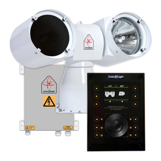
- Page 1 SEARCHLIGHT SYSTEM BY COLORLIGHT USER'S MANUAL CL20, CL25, CL35 Prerelease.5 2011-02...
-
Page 2: Table Of Contents
CONTENT WARNINGS AND INFORMATION ..................4 COLORLIGHT SEARCHLIGHT SYSTEM................6 INSTALLATION ........................7 Physical handling of the searchlight ................ 7 Mounting of the anti-vibration dampers ..............7 Specifications and drawings ..................8 3.3.1 Operator Panel ........................8 3.3.3 Electrical box ........................... 9 3.3.4... - Page 3 12.7 Status ........................33 12.8 Settings ........................33 12.8.1 Backlight brightness ......................33 12.8.2 Language (optional function) .................... 34 12.8.3 Joystick direction ....................... 34 12.8.4 Lamp life ..........................35 12.8.5 Maximum rotation speed ....................36 12.8.6 Installation ......................... 37 CABINET CARD MENU SYSTEM ................42 13.1 Inputs ........................
-
Page 4: Warnings And Information
UV-light! (models -12, -21, -22) The UV-light used by ColorLight is chosen for most efficient result in marine applications. The wavelengths are below 400 nanometers, thus not visible for the human eye. An intensive radiation is generated from the high luminance of the arch inside the bulb and should not be glared into from close distance. - Page 5 Be sure to wipe dry the bulb surface afterwards. Reflectors The parabolic reflectors developed by ColorLight have an extremely smooth surface to focus the light in wide or narrow beam. Bare fingers should never touch the reflector surface. If inadvertently touched, the reflector surface should immediately be degreased with alcohol and a soft lint free cloth.
-
Page 6: Colorlight Searchlight System
COLORLIGHT SEARCHLIGHT SYSTEM ColorLight has with its newly developed control system for searchlights opened for a flexible and future-proof system in which several searchlight assemblies (CL20, CL25 and CL35) and operator panels can be connected to a dedicated network and communicate via the Ethernet protocol. -
Page 7: Installation
INSTALLATION Physical handling of the searchlight Lift only the searchlight by the temporary lift loop on top of the center house. Lifting at the lamp houses may damage the construction. After safely fixed the searchlight, remove the lift loop. Lift here! Mounting of the anti-vibration dampers The picture shows how the dampers are mounted to avoid vibrations that can damage the mechanics and shorten the life of the bulbs. -
Page 8: Specifications And Drawings
Specifications and drawings 3.3.1 Operator Panel Operator Panel User Interface 2.4” (240 xRGBx320) Size See drawing "Operator Panel 3G" Display Weight (kg) 0,55 Push buttons with led ilumination 12 pcs Panel Anodized Aluminum Communication Protocol: Ethernet Enclosure ABS 2mm Environment Gasket (optional) EPDM Operational temperature... -
Page 9: Electrical Box
3.3.3 Electrical box Box details User Interface 2.4” (240 xRGBx320) Size See drawing "CL25/35 Electronic box" Display Weight (kg) Push buttons with led ilumination 12 pcs Material Steel Communication Protocol: Ethernet OP / CAN searchlight Color RAL 7035 powder-coated Environment Cooling Fan 80mm Operational temperature... -
Page 10: Cl20
3.3.4 CL20 Operator Panel User Interface 2.4” (240 xRGBx320) Size See drawing "CL20 Searchlight" Display Weight (kg) 0,55 Push buttons with led ilumination 12 pcs Panel Anodized Aluminum Communication Protocol: Ethernet Enclosure ABS 2mm Environment Gasket (optional) EPDM Operational temperature -40º... -
Page 11: Cl25
3.3.5 CL25 Operator Panel User Interface 2.4” (240 xRGBx320) Size See drawing "Operator Panel 3G" Display Weight (kg) 0,55 Push buttons with led ilumination 12 pcs Panel Anodized Aluminum Communication Protocol: Ethernet Enclosure ABS 2mm Environment Gasket (optional) EPDM Operational temperature -40º... -
Page 12: Cl35
3.3.6 CL35 Operator Panel User Interface 2.4” (240 xRGBx320) Size See drawing "Operator Panel 3G" Display Weight (kg) 0,55 Push buttons with led ilumination 12 pcs Panel Anodized Aluminum Communication Protocol: Ethernet Enclosure ABS 2mm Environment Gasket (optional) EPDM Operational temperature -40º... -
Page 13: Operator Panel, Overview
OPERATOR PANEL, OVERVIEW. Figure 1: The operating panel. 1. "Soft button": the function appears in the display window next to the button. 2. Left lamp on / off. 3. Left focus (the same function as No. 4). 4. Left focus (the same function as No. 3). 5. -
Page 14: Display Symbols And Messages
DISPLAY SYMBOLS AND MESSAGES Symbol for switched of white light. Symbol for switched on white light. Error symbol for white light indicates a problem during switch on or if the bulb breaks down during operation. The operator has three switch-on attempts in a two minute interval without setting the sum alarm output. - Page 15 This symbol indicates that the bulb has less than 200 hours left of expected lifetime. This warning can be chosen by the operator to be shown or not. Please 11.8.4 Lamp life for more detailed instruction. Each bulb has its own symbol showing in the lower left or right corner of the display.
-
Page 16: Actions After Installation Or Power Failure
ACTIONS AFTER INSTALLATION OR POWER FAILURE At the first boot after installation or power failure, the searchlight must be synchronized with the control system. After installation or power failure of the electric box you can use the searchlights main functions like joystick control, light on/off and focus but in order to be able to use positioning functions such as display indicator*, parking position, sweep*, fixed positions* or surveillance*, the searchlight must be synchronized with the control system. -
Page 17: Starting System
Pressing any button on the operator panel will activate the system and the display will now show the indicator* image or just the ColorLight logotype. Buttons and symbols are now brighter and both buttons, symbols and display intensity can be adjusted, please see 11.8.1 Backlight brightness. -
Page 18: Joystick Functions
The joystick (8) moves the searchlight horizontally and vertically. There are no limitations to the movement of the searchlight thanks to the slip ring technology developed by ColorLight. The more the joystick is moved to its end position the faster the searchlight rotates*. -
Page 19: Switch On Light
SWITCH ON LIGHT The searchlight is equipped with two bulbs which can be turned on / off separately by pressing (3) to turn on the left light and (6) to turn on the right light. To turn off the light just press the same button again. -
Page 20: Focus
10. FOCUS Pressing the focus buttons (3) or (4) changes the focus for the left lamp house and buttons (6) or (7) changes focus for the right lamp house. As long as a focus button is pressed the bulb moves in and out which changes the focus of the light. -
Page 21: Quick Start Menu
The quick start menu will close after 5 seconds. 11.1 Fixed positions (optional function) Fixed position is an option for the ColorLight Searchlight System and can only be accessed if activated. There are up to four different programmable fixed positions in ColorLights Searchlight System. -
Page 22: Store Fixed Position
11.1.2 Store fixed position If no position has been stored or the searchlight is at the stored position then the searchlight will not move. To store a new or change a fixed position, enter one of the fixed positions in the menu. If there is a preprogrammed fixed position the searchlight will start to move to that position. -
Page 23: Sweep (Optional Function)
11.2 Sweep (optional function) Sweep is an option for the ColorLight Searchlight System and can only be accessed if activated. A sweep is where the searchlight automatically moves back and forth in the horizontal plane. 11.2.1 New Sweep To enter the "Sweep" submenu, open up the quick start menu and press the left middle button "Sweep". -
Page 24: Modify Sweep Parameters
11.2.2 Modify sweep parameters To modify the sweep angle and / or the center of the sweep enter the “Sweep” menu and navigate down to “Modify”, press OK. In this menu changes to the sweep angle and center of the sweep can be modified in both runtime and stand still. - Page 25 The default speed of the sweep is set to 50% of the maximum speed of the searchlight. To change the speed of the sweep enter the “Sweep” menu and navigate down to “Speed”. Press “OK” to enter the “Speed” submenu. To change the speed move the joystick up or down to desired speed, press “OK”...
-
Page 26: Surveillance (Optional Function)
11.3 Surveillance (optional function) Surveillance is an option for the ColorLight Searchlight System and can only be accessed if activated. Surveillance is an advanced sweep where up to five points any ware can be set to be surveillanced. 11.3.1 Setting a new surveillance sweep To set a new surveillance sweep the number of positions must first be set. - Page 27 In this menu you can choose from two to five positions to be used in a surveillance sweep. Press “OK” to save and exit back to the “Surveillance” submenu. There are five positions that can be programmed in a surveillance sweep. To set the positions in a surveillance sweep enter the “Positions”...
-
Page 28: Changing Surveillance Settings
After pressing “Store” a new menu will appear, Pause Length. This is how long the searchlight will stay at this position until starting to move to the next position. Pause length can be set between zero and ten seconds. Repeat this for the desired number of positions wanted in a surveillance sweep. When done go back to the “Surveillance”... - Page 29 Navigate to the preferred setting and press “OK” to save the setting and return to the “Surveillance” menu. “Speed” is where the speed of the rotation of the searchlight is set. Default setting is 50% of maximum speed of the searchlight. To change the speed of the surveillance sweep enter the “Surveillance”...
-
Page 30: Switch
11.4 Switch If there are more than one ColorLight Searchlight in the system any operating panel can control any of the connected ColorLight searchlights. Every searchlight should be given a unique name during installation for this to work properly. To enter the “Switch” submenu open up the quick start menu and press the upper right button. -
Page 31: Off And Park
11.5 Off and park By pressing the "Park" any lighted lamp will be turned off and the searchlight will automatically look up the preprogrammed parking position, during this time you'll see "Parking ..." in the bottom middle of the display. When parked the operator panel will turn off the display after a few seconds and the LEDs behind the buttons will be dimmed to a lower intensity. -
Page 32: Main Menu
12. MAIN MENU From the quick start menu, select "Menu" to enter the system's main menu. To navigate the main menu, use the joystick; push the joystick forward/up once to go up a step in the menu and backwards/down to go down one step. Keep holding the joystick up or down will scroll up and down in menus with “autorepeat”. -
Page 33: Info
12.6 Info This menu shows information that is very useful to have handy during support from ColorLight if any problems occur or any options should be added to the operator panel after purchase (more about this later under 11.8.6.5 Options setup. -
Page 34: Language (Optional Function)
This is an option and different sets of languages can be installed from ColorLight at delivery. This is an option changing upon customer demands and requests, please feel free to call ColorLight to see which different sets that are available. -
Page 35: Lamp Life
Lamp life warning menu will make it possible for the operator to chose if the lamp life warning feature should be activated or not. See 8 SWITCH ON LIGHT. The warning is normally enabled when system is shipped from ColorLight. User’s Manual Page 35... -
Page 36: Maximum Rotation Speed
12.8.5 Maximum rotation speed This menu gives the operator the opportunity to set the maximum rotationspeed of the system. Use the joystick to increase or decrease the speed by moving the joystick up or down. Don‟t forget to make an “OK” button push or move the joystick to the right to having the change to take effect in the system. -
Page 37: Installation
12.8.6 Installation In this menu there are five sub menus each described below: 12.8.6.1 Store origin This menu is used to calibrate the systems indicator* where the “ZERO” point are set for both vertical and horizontal axis. Before the “Store origin” command is stored it‟s necessary that the synchronization between operator panel and electrical box is done properly. - Page 38 Press “OK” to save the new park position and return to the default logo screen or display indicator*-screen ColorLight recommend that the park position should be approximately 70 degrees down for the vertical axis relatively to the horizontal plane. This recommended parking position is the most effective position to avoid sand, rain, snow etc.
- Page 39 12.8.6.3 Name system The dedicated ColorLight network can contain several searchlights and operator panels. To make the whole network easy to navigate; each electrical box and its corresponding searchlight can be named to a well known name for the operator.
- Page 40 12.8.6.4 Start test sequence This menu starts a test sequence which tests the movement of the lamp housings and focus for each lamp house one at a time. The test sequence will perform as follows: At test sequence startup the lamp housing will be moved to parking position. The horizontal axis will be rotated a fully revolution clockwise.
- Page 41 The “codes” are individual for each operator panel. To get access to the “codes” the customer needs to call ColorLight for quotation. ColorLight need the MAC address for the relevant operator panel to be able to get the right code for their customer. Please see 11.6 Info.
-
Page 42: Cabinet Card Menu System
13. CABINET CARD MENU SYSTEM This chapter describes the menu system of the ColorLight Cabinet Card displayed on the on- board LCD. Down Right 13.1 Inputs The user interacts with the menu system using the three buttons, the Down button, the Right button and the OK button. -
Page 43: Category 1: About
13.2 Category 1: About In this chapter all of Category 1 menu items will be explained. 13.2.1 1.1 MAC Address Displays the MAC address of the Cabinet Card, according to the standard (IEEE 802) in six groups of two hexadecimal digits, separated by colons („:‟), in transmission order, e.g. “01:23:45:67:89:ab”. -
Page 44: Category 2: Diagnostics (Support Tool)
Press the OK button to run the on-board diagnostic test suite to sense the electrical and mechanical condition of the searchlight. (contact Colorlight for help with this feature). T1. Measurement of voltage and current when the searchlight is in “non operating mode”... -
Page 45: Category 3: Usage Stats
13.4 Category 3: Usage Stats In this chapter all of Category 3 menu items will be explained. 13.4.1 3.1 Left Light Displays the usage of the left light source in hours:minutes:seconds, e.g. “Left: 1:23:45”. 13.4.2 3.2 Right Light Displays the usage of the right light source in hours:minutes:seconds, e.g. “Right: 1:23:45”. 13.4.3 3.3 Reset Left Resets the usage counter of the left light source. -
Page 46: System Identification Page
On this page you can find information about your system as it was configured when it left colorlight. In case of system support please mail us the components serialnumbers. Remember to keep this page updated if adding or replacing components like operator panels. -
Page 47: Support
15. SUPPORT If you have questions about the searchlight and its features, please contact ColorLight technical support worldwide, see www.colorlight.com for contact details. Or contact ColorLight head office: Color Light AB Engineering-Color Light cl@colorlight.com Phone: +46 353 8270 Fax: +46 35 38279 If you want to upgrade your system with additional options (see 11.8.6.5), please contact:...
Need help?
Do you have a question about the CL20 Series and is the answer not in the manual?
Questions and answers