
Related Manuals for Ormazabal ekor.rpa Series

Summary of Contents for Ormazabal ekor.rpa Series
- Page 1 ekor.rpa Protection, metering and control multifunction unit General Instructions IG-267-EN, version 01, 07/04/2017...
- Page 2 Therefore, the use of this equipment poses electrical, mechanical and thermal risks. In order to ensure an acceptable level of protection for people and property, and in compliance with applicable environmental recommendations, Ormazabal designs and manufactures its products according to the principle of integrated safety, based on the following criteria: •...
-
Page 3: Table Of Contents
General Instructions Contents ekor.rpa Contents 1. General description ..........5 4.6. Voltage units .......33 4.6.1. - Page 4 Contents General Instructions ekor.rpa 8. Protection, metering and control models .....56 11. User interface ............85 8.1. Description of models vs functions ..56 11.1. Web server. Checking and 8.1.1. ekor.rpa-110....... .58 configuring parameters .
-
Page 5: General Description
EN 60255, EN 61000, EN 62271-200, EN 60068, EN 60044. • IEC 60255, IEC 61000, IEC 62271-200, IEC 60068, IEC 60044, IEC 61958. Integrating the ekor.rpa units in the Ormazabal cubicle system allows specific products for requirements in different facilities. The ekor.rpa-100 units in the ekor.rpa range have outputs to, either locally or remotely, open and close the switch in the cubicle where it is installed. -
Page 6: General Operating Features
General description General Instructions ekor.rpa 1.1. General operating features All the relays of the ekor.rpa-100 series include a The ekor.rpa-100 relays are equipped with a keypad for microprocessor for processing the metering sensor signals. local display, set-up and operation of the unit, as well as They process voltage and current meterings and eliminate communication ports to handle these functions from a PC, the influence of transient states, calculate the magnitudes... -
Page 7: Components
General Instructions General description ekor.rpa 1.2. Components The parts which make up the ekor.rpa-100 protection, metering and control series are the electronic relay, voltage and current sensors, auxiliary circuits (terminal block and wiring), the bistable release and the tripping coil. Terminal block ekor.rpa electronic relay Voltage and current sensors... -
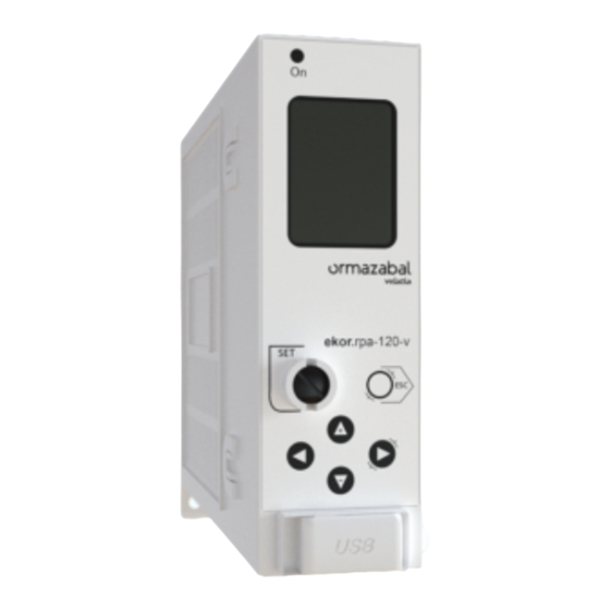
Page 8: Electronic Relay
General description General Instructions ekor.rpa 1.2.1. Electronic relay The electronic relay has a keyboard and display to set and view the protection and control parameters. Moreover, the display provides information of the system's meterings, alarms and control signals in real time. The keyboard includes a seal on the <<SET>>... -
Page 9: Current Sensors
The current sensors are toroidal-core current transformers with a 300/1 A or 1000/1 A or 2500/1 ratio, depending on the models. These transformers cover the entire operation range of Ormazabal cubicles, from rated currents 5A up to 2500 A. The phase toroidal transformers are factory-installed in the cubicle bushings, which significantly simplifies on-site assembly and connection. -
Page 10: Binox" Bistable Tripping Device And Tripping Coil
Ormazabal. To achieve this, Ormazabal counts on the CIT, its Research 2. UDEX: Demonstration and experimentation unit and Technology Centre, which represents an essential consisting of a fully configurable, independent instrument in R&D, in order to capture and improve existing... -
Page 11: Communications
General Instructions General description ekor.rpa 1.4. Communications All the relays of the ekor.rpa-100 units have two TCP/IP connection Ethernet ports and a Web server for configuration. They also have a front mini-USB port for maintenance and two rear ports with serial communication RS-485 twisted pair (COM0 and COM1) for remote control. -
Page 12: Applications
• They reduce the fault time using a combination of fast switch trips and automatic reclosings, which results in This function is always associated with Ormazabal circuit- lesser damage caused by the fault and generates a lower breaker cubicles. number of permanent faults derived from transient faults. -
Page 13: Line Protection With Circuit-Breaker
General Instructions Applications ekor.rpa 2.3. Line protection with circuit-breaker The purpose of the line protection is to isolate this part The underground cables have earth coupling capacities, of the network in case of fault, without it affecting the which causes the single phase faults to include capacitive rest of the lines. -
Page 14: Transformer Protection
Applications General Instructions ekor.rpa In addition, the ekor.rpa-100 equipment, ekor.rpa-120 59/59N ≡ Overvoltage and residual overvoltage • relay. Protects against phase and neutral overvoltages model, also have the following functions: in the lines with 2 units for each phase and neutral, one 67/67N and 67NS ≡... - Page 15 General Instructions Applications ekor.rpa In addition, the ekor.rpa-100 equipment, ekor.rpa-120 protection functions, available models ekor.rpa-110, which must be implemented to protect models, also have the following functions: distribution transformers with power ratings between 160 67/67N and 67NS ≡ Directional overcurrent relay, •...
-
Page 16: Automatic Transfer
Applications General Instructions ekor.rpa 2.5. Automatic transfer The automatic transfer of lines with circuit-breakers minimises power outages in loads fed by transformer or switching substations with more than one incoming line, thereby improving continuity of service. Under normal conditions with voltage present on two possible incoming lines, the switch selected as preferred remains closed and the reserve one is opened. -
Page 17: Protection And Control Of Mv Interconnection Stations
General Instructions Applications ekor.rpa 2.7. Protection and control of MV interconnection stations In MV customers where an ekor.rpa-100 relay is installed, The accessible information would be as follows: either in protection cubicles with circuit-breaker or fuses • Cubicle position which protect the MV outgoing, information on this outgoing can be sent to the SCADA both by the web and •... -
Page 18: Metering Functions
Metering functions General Instructions ekor.rpa Metering functions 3.1. Current and voltage metering The unit has four current reading inputs (I and I and three voltage reading inputs (V and V ). Each of them are conditioned and digitised in order to carry out the calculation. -
Page 19: Power Meterings
General Instructions Metering functions ekor.rpa 3.2. Power meterings The powers which are monitored (locally or remotely) are The meterings are made up of: 1.28 second integrated meterings of the calculated RMS • Single-phase: Active PA, PB and PC and Reactive QA, QB instantaneous values. -
Page 20: Protection Functions
Protection functions General Instructions ekor.rpa Protection functions 4.1. Overcurrent units The ekor.rpa-100 systems are fitted with the following Neutral (Calculated): overcurrent protection units: • Two neutral timed overcurrent units (1 x 51N, 1 x 51(2) Phases: • A neutral instantaneous overcurrent unit (1 x 50N). •... -
Page 21: Instantaneous Overcurrent Units
General Instructions Protection functions ekor.rpa 4.1.2. Instantaneous overcurrent units Torque control: Directional tripping mask (OFF, The phase, neutral and sensitive neutral instantaneous • units start up if the fundamental value of the magnitude for FORWARD or REVERSE). To indicate the direction for each unit exceeds the value 1.00 times the adjusted start- tripping: up, and are reset when this value is below 0.95 times the... -
Page 22: Ultra-Sensitive Earth
Protection functions General Instructions ekor.rpa Basically, the diagram shows that, whenever a magnitude Moreover, the overcurrent units can be blocked by the maximum current blocking and second harmonic measured in real-time (Ix) exceeds the setpoint value (l pick up blocking units detailed in the following sections. setting), a time counter counts down (counter: f (curve, index, time), tripping when completely expired. -
Page 23: Directional Units
General Instructions Protection functions ekor.rpa 4.3. Directional units The ekor.rpa-100 model 120 systems have the following The directional units are combined with the overcurrent units when taking a decision on tripping. In accordance with directional units: the "torque control" direction setting (Forward or Reverse) •... -
Page 24: Neutral And Sensitive Neutral
Protection functions General Instructions ekor.rpa 4.3.2. Neutral and sensitive neutral directional units The neutral and sensitive neutral directional units include two different criteria to determine direction: Directional criterion and wattmetric criterion. The criterion is selected through a setting in the unit itself. Angular criterion The angular criterion of the neutral and sensitive neutral directional units is based on the phase difference between... -
Page 25: Thermal Image Unit
General Instructions Protection functions ekor.rpa The unit will indicate Forward direction in the following The figure below shows an example of operation for the conditions: neutral directional unit with wattmetric criterion: • The residual current signal (3I ) drops in the following zone: The residual active power is lower than - P The reverse direction zone will be the opposite of the... -
Page 26: Estimated Thermal Capacity
Protection functions General Instructions ekor.rpa 4.4.1. Estimated thermal capacity The system estimates thermal capacity through the phase currents (I and I ), using the following formula: Where: : Estimated thermal capacity at instant n : Estimated thermal capacity at instant n-1 Δt: Time interval between consecutive n and n-1 instants τ: Cooling or heating constant If T <... -
Page 27: Functionality
General Instructions Protection functions ekor.rpa 4.4.2. Functionality The thermal image unit starts up (with an alarm signal) if the The time taken to reach tripping, based on a thermal thermal capacity value exceeds the alarm level setting (%), capacity equal to zero, given by the following formula: tripping whenever the trip level setting is exceeded (%). -
Page 28: Block Diagram
Protection functions General Instructions ekor.rpa 4.4.3. Block diagram The thermal image unit complies with the following block diagram : Metering Input signal Output signal Settings Figure 4.8. Block diagram The thermal image unit generates the following signal: Moreover, the thermal image unit can be blocked by the maximum current blocking unit detailed in the following Alarm: Activated when the estimated magnitude of •... -
Page 29: Broken Conductor Unit
General Instructions Protection functions ekor.rpa 4.5. Broken conductor unit The ekor.rpa-100 model 120 systems are fitted with the The broken conductor unit (46 Broken Conductor) can broken conductor unit (46BC). be used to detect broken conductors, by monitoring the sequence currents, and another series of conditions Conventional protection functions cannot detect conditions detailed in this section. - Page 30 Protection functions General Instructions ekor.rpa The following image shows an example of calculation of the sequence (situation which can come about in lines which sequences based on an imbalanced system. It is observed are not uniformly charged in the three phases): that the system has a large inverse component, but no zero- Line currents Direct-sequence currents...
- Page 31 General Instructions Protection functions ekor.rpa Another example which applies for the case of broken through the broken conductor) and the other two counter- conductors could be as follows: One of the phases with direction phases: no current (without the capacitive currents which can go Line currents Direct-sequence currents Inverse-sequence currents...
-
Page 32: Functionality
Protection functions General Instructions ekor.rpa 4.5.2. Functionality Unit timing: Unit tripping time (from 0.05 s to 600.00 s). The broken conductor unit starts up when a series of • conditions are met, as detailed below, and is reset when any Minimum current threshold for phases: Phase current •... -
Page 33: Voltage Units
General Instructions Protection functions ekor.rpa The four conditions which make the broken conductor unit start up are: Figure 4.12. Conditions A, B, C and D The broken conductor unit generates the following signal: Moreover, the broken conductor unit can be blocked by the maximum current blocking unit detailed in the following Pick up: Activated when the four conditions come •... -
Page 34: Timed Overvoltage Units
Protection functions General Instructions ekor.rpa 4.6.1. Timed overvoltage units The phase and neutral timed units start up if the The settings for the timed units are: fundamental value of the magnitude (single or compound Enabling the unit: Enable/disable the unit (ON/OFF). •... -
Page 35: Timed Undervoltage Units
General Instructions Protection functions ekor.rpa 4.6.3. Timed undervoltage units The phase timed units start up if the fundamental value of The settings for the timed units are: the magnitude (single or compound voltage, which can be Enabling the unit: Enable/disable the unit (ON/OFF). •... -
Page 36: Block Diagram
Protection functions General Instructions ekor.rpa 4.6.5. Block diagram Any voltage unit complying with the diagram shown below. Metering Input signal Output signal Settings Figure 4.13. Block diagram The diagram represents, whenever the magnitude measured Moreover, the voltage units can be blocked by the maximum current blocking unit detailed in the following in real time (Vx) is: a) higher in the case of overvoltage units: 59 or, b) lower in the case of undervoltage units: 27 than the... -
Page 37: Second Harmonic Blocking Unit
General Instructions Protection functions ekor.rpa 4.7. Second harmonic blocking unit The ekor.rpa-100 systems are fitted with the second • High fundamental current value. harmonic blocking unit. • High second harmonic current value. This function blocks the overcurrent units whenever the transformer energisation conditions are met: 4.7.1. - Page 38 Protection functions General Instructions ekor.rpa Minimum current threshold for phases: Fundamental The settings for the second harmonic blocking unit are: • phase current as of which the condition corresponding Enabling the unit: Enable/disable the unit (ON/OFF). • to minimum fundamental current is met. Variable ranges Second harmonic threshold: Second harmonic current in accordance with the current transformers used.
-
Page 39: Block Diagram
General Instructions Protection functions ekor.rpa 4.7.2. Block diagram The second harmonic blocking unit complies with the following block diagram: Figure 4.14. Block diagram IG-267-EN versión 01; 07/04/2017... - Page 40 Protection functions General Instructions ekor.rpa UHARM_IN_BLOCK: Signal which indicates whether The second harmonic blocking unit generates the following • signal: the calculated neutral complies with the conditions for second harmonic blocking or not. UHARM_IA_BLOCK: Signal which indicates whether • UHARM_INS_BLOCK: Signal which indicates whether •...
-
Page 41: Block By I
General Instructions Protection functions ekor.rpa 4.8. Block by I The maximum current blocking unit is implemented in If the current in any of the 3 phases is above the value set the ekor.rpa-100 systems, p type, used in fuse protection in the maximum current blocking unit, all protection units will be blocked until current drops below the set value. -
Page 42: Detection, Automation And Control Functions
Detection, automation and control functions General Instructions ekor.rpa Detection, automation and control functions 5.1. Recloser automation 5.1.1. Functionality recloser automation implemented The recloser cycle starts when any of the overcurrent units ekor.rpa-100 systems used in protection cubicles with trip whilst the recloser is in automatic and unblocked. Under circuit-breaker. -
Page 43: Settings
General Instructions Detection, automation and control functions ekor.rpa 5.1.3. Settings Reference voltage standby time: Defines the time The setting parameters of the recloser automation are: • to wait after the overcurrent unit trips until the Vref Enabling the unit: Corresponds to recloser automation •... - Page 44 Detection, automation and control functions General Instructions ekor.rpa FINAL TRIP: Indicates that the trip caused by the RECLOSING ORDER: This is the switch closing • • overcurrent unit has been final, and there will be no order which automation generates after timing the subsequent reclosing.
-
Page 45: Voltage Presence/Absence Automation
General Instructions Detection, automation and control functions ekor.rpa 5.2. Voltage presence/absence automation 5.2.1. Functionality This automation allows detection of presence or absence of voltage in those lines where the ekor.rpa unit is installed. The voltage presence/absence automation individually checks for the presence or absence of voltage in each of the line phases. -
Page 46: Switch Control
Detection, automation and control functions General Instructions ekor.rpa 5.3. Switch control 5.3.1. Introduction The ekor.rpa-100 units are equipped with inputs and outputs to operate the switch of the cubicle where are installed, and monitoring functions that detect the status of the primary circuit. The unit ensures that the switch operation is performed within the time allowed by the switchgear. -
Page 47: Switch Control Statuses
General Instructions Detection, automation and control functions ekor.rpa 5.3.3. Switch control statuses The switch control unit implemented in the ekor.rpa-100 Opening failure by remote opening command: • system generates a series of signals which report its status. Indicates that there was an error in the switch opening These signallings are: caused by a remote control order. -
Page 48: Sensors
Sensors General Instructions ekor.rpa Sensors 6.1. Current sensors The sensors are designed for optimal adaptation to the technology of current digital equipment. The protection, metering and control units for these sensors operate with the same algorithms and have the same consistency as conventional devices, adding more advanced algorithms and functions. -
Page 49: Of Current Sensors
General Instructions Sensors ekor.rpa 6.1.1. Functional characteristics of current sensors The current sensors are toroidal-core current transformers These sensors are encapsulated in self-extinguishing with a high transformation ratio and low rated burden. polyurethane resin. Phase current toroidal transformers Ratio 300/1 A 1000/1 A 2500/1 A Metering range... -
Page 50: Vector Sum/Zero-Sequence Wiring
Sensors General Instructions ekor.rpa 6.1.2. Vector sum/zero-sequence wiring The transformers described above can be connected in two ways, depending on whether a zero-sequence toroidal current transformer is used or not. Figure 6.3. Detection of earth current by vector sum Figure 6.4. Detection of earth current with zero-sequence transformer Zero-sequence current toroidal transformers Ratio... -
Page 51: Voltage Sensors
General Instructions Sensors ekor.rpa 6.2. Voltage sensors 6.2.1. Bushing The cubicle voltage is detected using a capacitor divider incorporated in the cubicle’s bushings. The following precisions are ensured, in accordance with the type of acquisition: Figure 6.5. Voltage pickup Bushing Conventional Type Double screen... -
Page 52: Ekor.evt-C
- 10 °C to + 60 °C Connectors Metering cable Coaxial 50 Ω model RG1747/U IEC 61869-3 Reference standard IEC 60044-7 For the BNC output identified as PLC communications, contact Ormazabal's technical-commercial department Table 6.5. ekor.evt-c sensor Figure 6.8. ekor.evt-c dimensions IG-267-EN versión 01; 07/04/2017... -
Page 53: Technical Characteristics Of The Equipment
General Instructions Technical characteristics of the equipment ekor.rpa Technical characteristics of the equipment 7.1. Rated values Power supply 40 V ...90 V ± 20 %; 12 VA 24 V ...120 V ± 10 %; 6 W 1A Current inputs Secondary phase Metering 1 mA...1.3 A Protection... -
Page 54: Insulation Tests
Technical characteristics of the equipment General Instructions ekor.rpa 7.3. Insulation tests Insulation resistance IEC 60255-5 (2000) 500 V ; >100 MΩ Dielectric strength IEC 60255-5 (2000) 2 kV ; 50 Hz; 1 min 1 kV ; 50 Hz; 1 min Insulation with voltage impulses IEC 60255-5 (2000) - Common mode:... -
Page 55: Climatic Tests
General Instructions Technical characteristics of the equipment ekor.rpa 7.5. Climatic tests Damp heat IEC 60068-2-78 (2001) 40 °C; 93 % humidity; 96 h Dry heat IEC 60068-2-2 (2007) 70 °C; 16 h Cold IEC 60068-2-1 (2001) 25 °C; 16 h Temperature variation IEC 60068-2-14 (2009) - 25 °C/70 °C;... -
Page 56: Protection, Metering And Control Models
Protection, metering and control models General Instructions ekor.rpa Protection, metering and control models 8.1. Description of models vs functions The units to be described are the ekor.rpa-110 and The cubicles (functional units) interconnect to each other ekor.rpa-120 models. Some models are fitted with v type and to the ekor.uct (Compact remote control unit, associated technical documentation IG-151) by way of interconnection (installed in circuit-breaker protection cubicles) and p type... - Page 57 General Instructions Protection, metering and control models ekor.rpa Bistable output Digital inputs: Switch status, earthing switch ETH-0 Terminals X2 status, external trip, etc. ETH-1 Digital outputs: Trip signal. Open switch. Terminals X2 Terminal Block X1 Close the switch. Error (WD)... Terminal Block X2 Tripping COM0...
-
Page 58: Ekor.rpa-110
Protection, metering and control models General Instructions ekor.rpa 8.1.1. ekor.rpa-110 The ekor.rpa-110 protection unit is a unit with multilevel It supervises the current meterings and detects the overcurrent protection functions (50/51(1)/51(2)/50N/51N presence/absence of voltage. (1)/51N(2)/50NS/51NS(1)/51NS(2)), automatic recloser (79), command and control of the switch (52), etc. 8.1.2. -
Page 59: Ekor.rpa-100-V/Ekor.rpa-100-P
General Instructions Protection, metering and control models ekor.rpa 8.1.3. ekor.rpa-100-v/ekor.rpa-100-p The ekor.rpa-110 and ekor.rpa-120 models include two The main applications v type units (circuit-breaker) are types of unit: v type for protection cubicles with circuit- used in are: general protection of lines, private installations, breaker, or p type for protection with fuses. -
Page 60: Relay Configurator
Slave PROCOME Communications ports Mini USB (front), local configuration with ekor.soft-xml 2 x Ethernet, local configuration with Web server 2 x RS-485, for remote control * For further information please ask Ormazabal’s technical-commercial department Table 8.1. ekor.rpa characteristics 8.1.4. Relay configurator The following configurator will be used to select the right unit within the ekor.rpa-100 series, in accordance with the... -
Page 61: Type Units
General Instructions Protection, metering and control models ekor.rpa 8.2. “v” type ekor.rpa-110-v and ekor.rpa-120-v units 8.2.1. Functional description The ekor.rpa-110-v and ekor.rpa-120-v units are designed for general protection of lines, transformer protection, etc. They are installed in circuit-breaker protection cubicles, where all protection functions are performed by the electronic unit. -
Page 62: Definition Of Digital Inputs/Outputs
Table 8.3. ekor.rpa inputs/outputs The functionality of the inputs and outputs presented is typical of cubicle installations: However, there is always the option of including different or new Ormazabal's configurations. Contact technical- commercial department in order to ensure new configurations are properly installed in the functional unit, or to obtain further information and details. -
Page 63: Installation In A Cubicle
General Instructions Protection, metering and control models ekor.rpa 8.2.3. Installation in a cubicle The components of the ekor.rpa-110-v and ekor.rpa-120-v (Terminal Block-G: Test blocks for voltage and current units are the electronic relay, voltage and current injection) are located in the top of the relay and at the back sensors, bistable tripping device (Binox), tripping coil and of the driving mechanism. -
Page 64: Checking And Maintenance
Optionally, other alternatives can be assessed, such as positioning the unit in a control box installed on the cubicle. For further information or details on configurations (schematic, etc.), contact Ormazabal's technical- commercial department for your zone. I&V Sensors Interconnection terminal block... - Page 65 General Instructions Protection, metering and control models ekor.rpa 4. Connect the trip indication signal (depending on the This testing method is also used when the primary circuit programmed function) to the tester's timer stop input. current values being tested are much greater than those produced by test equipment (normally greater than 100 A), 5.
-
Page 66: Type Units
Protection, metering and control models General Instructions ekor.rpa 8.3. “p” type ekor.rpa-110-p and ekor.rpa-120-p units 8.3.1. Functional description The ekor.rpa-110-p and ekor.rpa-120-p protection, metering and control units are focused on protection for distribution transformers. They are installed in fuse- combination switch cubicles so the electronic system performs all the protection functions, except high polyphase short-circuit values, which are cleared by the fuses. -
Page 67: Definition Of Digital Inputs/Outputs
General Instructions Protection, metering and control models ekor.rpa 8.3.2. Definition of digital inputs/outputs The ekor.rpa-110-p and ekor.rpa-120-p protection, metering and control units are fitted with a series of physical inputs and outputs that are isolated from the other independent circuits (terminals X2). The standard definition of the inputs and outputs is as follows: Physical inputs Physical ouputs... -
Page 68: Fuse Protection
Protection, metering and control models General Instructions ekor.rpa 8.3.3. Fuse protection The ekor.rpa-110/120-p unit is used for transformer 7. Instantaneous timing T>>. This value corresponds protection, and works in combination with the fuse to protection trip time in the event a short-circuit protection. - Page 69 General Instructions Protection, metering and control models ekor.rpa Choice of fuse 125 A Rated current 48 A Continuous overload 58 A Curve type E.I. Factor K = 0.2 Short-circuit level 404 A Instantaneous timing 400 ms Secondary three-phase short-circuit 960 A Fuse operation zone Relay operation zone Time...
- Page 70 Protection, metering and control models General Instructions ekor.rpa The earth unit setting depends on the characteristics of the criteria and types of neutral used in the networks, a single line where the unit is installed. In general, the earth fault parameterisation cannot be indicated;...
-
Page 71: Installation In A Cubicle
For further information or details on configurations (schematic, etc.), contact Ormazabal's technical- Interconection terminal block commercial department for your zone. Power and communications bus... -
Page 72: Checking And Maintenance
Protection, metering and control models General Instructions ekor.rpa 8.3.5. Checking and maintenance The solution for facilities with ekor.rpa-110-p and ekor.rpa-120-p units does not have a test terminal block in the standard solution, with the option of making the checks from primary only. In this type of cubicles, the current transformers are installed on the cable. -
Page 73: User Configuration Settings
General Instructions User configuration settings ekor.rpa User configuration settings The current units have a large number of configuration The applications necessary to transform the data into parameters and logical organisation is fundamental in order information or to share information are applications which to avoid errors in generating and translating the settings. - Page 74 User configuration settings General Instructions ekor.rpa Protection settings (PROTECTION) Settings Type Class Node Range Type Designation Min. Max. Step (unit) Enabling the unit Enable ON/OFF 6000.0 0.1 (A) Starting up the unit Pick_up* 15.0 20 000.0 0.1 (A) 37.5 50 000.0 0.1 (A) Phase timed IEC: DT, NI, VI, EI, STI and LTI...
- Page 75 General Instructions User configuration settings ekor.rpa Continuation Settings Type Class Node Range Type Designation Min. Max. Step (unit) Enabling the unit Enable ON/OFF 1500.0 0.1 (A) Pick_up* 5000.0 0.1 (A) (with vector sum) 5000.0 0.1 (A) Starting up the unit Pick_up* 1500.0 0.1 (A)
- Page 76 User configuration settings General Instructions ekor.rpa Continuation Settings Type Class Node Range Type Designation Min. Max. Step (unit) Enabling the unit Enable ON/OFF Base current Base_current Starting up the unit (I2/I1) Pick_up_ratio 0.05 0.50 0.01 (pu) Broken Unit timing Time 0.05 600.00 0.01 (s)
- Page 77 General Instructions User configuration settings ekor.rpa Continuation Settings Type Class Node Range Type Designation Min. Max. Step (unit) Enabling the unit Enable ON/OFF PHASE-TO-NEUTRAL Working voltage Voltage PHASE-TO-PHASE Overvoltage Starting up the unit Pick_up 72.0 0.1 (kV) timed unit(UNIT_59_ IEC: DT, NI, VI, EI, STI and LTI Time curve Curve TEMP)
- Page 78 User configuration settings General Instructions ekor.rpa Automation settings (AUTOMATISM) Settings Node Range Type Designation Min. Max. Step (unit) Enabling the unit Enable ON/OFF Number of reclosings Reclose_Number First recl. time for phases Phase_Reclosing_Time_1 0.05 600.00 0.01 (s) Neutral_Reclosing_ First recl. time for neutral 0.05 600.00 0.01 (s)
-
Page 79: Date And Time Settings
General Instructions User configuration settings ekor.rpa Communication settings (COMMUNICATION) Settings Node Range Type Designation Min. Max. Step (unit) Peripheral number Perif_Num Speed Baud rate 1200/2400/4800/9600/19200/38400 baud Parity Parity No/Odd/Even COM_485 Length Length Stop bits Stopbits Protocol Protocol CIRBUS/MODBUS/PROCOME COM_ Peripheral number Perif_Num VIRTUAL Protocol... -
Page 80: Log Record
Log record General Instructions ekor.rpa 10. Log record The logic equipment is organised into functional modules, as The classification for the different types of data is: indicated previously, grouped together in accordance with • Digital signals: TYPE/GROUP or CLASS/SUBGROUP or their condition, meaning any type of data is represented in NODE/NUMBER SIGNAL a specific structure with a specific name. -
Page 81: Structure Of The Report
General Instructions Log record ekor.rpa 10.1.2. Structure of the report 4. Current open by the switch. The fault report can be divided into five functional parts: 5. Record of events generated during the time window of 1. Information on the system the report belongs to. the fault. -
Page 82: List Of Available Signals
Log record General Instructions ekor.rpa 10.1.3. List of available signals Unit: Subgroup Type type/group • Pre-fault event • Reason for end fault: • UPs OFF, Fault cleared Records Fault report unit • Loss of power (V KO. Autosaved PowerDown) • Timeout reached. (Fault not cleared) •... - Page 83 General Instructions Log record ekor.rpa Continuation Unit: Subgroup Type type/group • Curve started up (PICK UP ON/OFF) Phase_1,2,3,N and NS • Curve met (TEMPORIZED ON/OFF) (P1) • Unit blocked (UNIT BLOCK ON/OFF) Timed overvoltage unit (P2) • Timing Blocked (TIMING BLOCK ON/OFF) (UNIT 59N-T) (P3) •...
-
Page 84: Event Record
Functional groups • Type: The numeration given to each event within each For further information or details of the events list of each specific installation, contact Ormazabal's technical- group. commercial department. • Description: The description text added to each event. -
Page 85: User Interface
General Instructions User interface ekor.rpa 11. User interface The system works as a file server (central file system) where • Configuration settings (XML Format) the files can be displayed through different user interfaces. • Date/time (XML format) Different files can be loaded and displayed by sending •... -
Page 86: Access To The Web Server: Local And Remote Access
User interface General Instructions ekor.rpa 11.1.2. Access to the Web server: Local and remote access The ekor.rpa has a web application server which is Remote access accessible by both HTTP and HTTPS. The remote access IP address will be the one defined in the This access can be in local or remote mode, using any of IP1 and IP2 associated to the substation, using the same the system's Ethernet ports. - Page 87 General Instructions User interface ekor.rpa Checking and modifying parameters using the Web server Meterings: The different meterings of the system are • shown. The website is divided into four main tabs: Maintenance, Logs, Configure and Leave. Maintenance This tab is used to keep users informed on data in real time and provide information on the status of the cubicle, alarms, current and voltage meterings, etc.
- Page 88 User interface General Instructions ekor.rpa Logs Events and operations record: Shows detailed This tab shows the different logs which can be downloaded • from the system: Substation events and alarms log, faults information on the events and alarms of the substation log, and changes of software version log.
- Page 89 General Instructions User interface ekor.rpa Configuration Password: Used to change the passwords for • administrator mode and display mode (when not This tab is used to configure the different parameters of the managed by LDAP). substation: Protection unit settings, remote IP addresses… Protection: Display and change protection unit settings.
-
Page 90: Keyboard/Display
User interface General Instructions ekor.rpa 11.2. Keyboard/Display 11.2.1. Introduction The electronic relay has a keyboard and display to set and The keyboard has 6 keys: view the protection and control parameters. Moreover, the display provides information of the system's meterings, alarms and control signals in real time. -
Page 91: Display Screen
General Instructions User interface ekor.rpa Example: In this example, part of the tree structure implemented in the display is shown; specifically, the navigation screens which should be used to access the sequence current metering (data screens) are shown. Based on the main “RPA MODEL”... - Page 92 User interface General Instructions ekor.rpa The screens which depend on each of the general screens mentioned in the table above are presented below. Settings Clock The screens for user settings (SETTINGs) are structured in The screens structure for the date and time is: the same way as in the .xml settings file.
- Page 93 General Instructions User interface ekor.rpa Logs The screen structure for the last 10 reports stored in the system is: Figure 11.20. Logs Every time there is a fault, it is shown on the display and a The user should press the ESC key in order to leave the priority screen with the fault information.
- Page 94 User interface General Instructions ekor.rpa Measures The screens structure for the system meterings is: Figure 11.21. Measures IG-267-EN versión 01; 07/04/2017...
- Page 95 General Instructions User interface ekor.rpa Information The screens structure for system information is: Figure 11.22. Information IG-267-EN versión 01; 07/04/2017...
-
Page 96: Error Codes
User interface General Instructions ekor.rpa 11.2.3. Error codes The ekor.rpa-100 units have a series of error codes used to warn the user regarding the different anomalies that may occur in the system. Figure 11.23. Error Each type of error has a unique error number defined, meaning its identification cannot be mistaken: Code shown on the display Meaning... -
Page 97: Fileserver In Usb Memory
General Instructions User interface ekor.rpa 11.3. Fileserver in USB memory The device shares different types of files with the user using a USB memory. This flash memory acts as a file server, where the system can update its configuration or information using the import and export commands (commands sent by the user by activating two pushbuttons). -
Page 98: Use Of The Interface
User interface General Instructions ekor.rpa The following elements can be found on the drive: ekorSoftXML.exe: Settings display software. “Faults” folder: Directory where the faults recorded by • • the system are saved. "Settings” folder: Directory where the system's settings • "Measures”... - Page 99 General Instructions User interface ekor.rpa The firmware or configuration update tasks are important The following is required to configure the system with device updates and should only be carried out when “user.xml” for user settings and “RTC.xml” for date/time: necessary and by qualified personnel. These files are for 1.
-
Page 100: Ekor.soft-Xml
User interface General Instructions ekor.rpa 11.3.3. ekor.soft-xml The file “ekor.soft-xml.exe” as an executable file for browsing Choose the drive, and the right-hand column will show the the USB drive fileserver. This executable file is on the system files which can be displayed and/or modified (USER: User itself and does not need any communications connection, and RTC settings: Date/time). - Page 101 General Instructions User interface ekor.rpa The new settings can be sent to the system as follows: • Confirm that the update is correct by clicking on the Check button: • Click on the "Send to Device" button. • The software will ask for a password. Enter the correct Password (0000 by default) and click on the OK button: Figure 11.31.
-
Page 102: Communications
Communications General Instructions ekor.rpa 12. Communications 12.1. Physical medium: RS-485 The physical medium used to establish telecontrol The communication parameters for the RS-485 COM0 port communications for the ekor.rpa-100 series is a twisted pair can be modified using the user settings. These settings are cable which connects to the rear RS-485 port (identified as classified in the field “Communications/COM_485”... - Page 103 General Instructions Communications ekor.rpa Read/write functions In principle, only two functions will be implemented, one for reading and another for writing data. Data reading Question: Start Address Function Data Silence DESC ‘3’ ADDR-H ADDR-L NDATA-H NDATA-L 16 bits Silence Table 12.2. Data reading.
- Page 104 Communications General Instructions ekor.rpa Response in case of error Start Address Function Error-Code Silence DESC FUNC_ERR CODE_ERROR 16 bits Silence Table 12.5. Data Writing. Response in case of error Where: DESC Slave address FUNC_ERR Code of the function requested, with the most significant bit at 1 CODI_ERROR Code of the error occurred ‘1’...
- Page 105 General Instructions Communications ekor.rpa Clock (0 x 03XX) Address Field Description Size Read/write 0 x 0300 YEAR Year (from 2000 to 2059) 16 bits Read/write 0 x 0301 MONTH Month (from 1 to 12) DAY (FROM 1st to 31st) 16 bits Read/write 0 x 0302 TIME...
- Page 106 Communications General Instructions ekor.rpa Continuation Address Field Description Size Read/write 0 x 0733 ANG(VC/VA) VC/VA angle [from 0 (0.0°) to 3599 (359.9°)] 16 bits Read 0 x 0734 ANG(VN/VA) VN/VA angle [from 0 (0.0°) to 3599 (359.9°)] 16 bits Read 0 x 0735 ANG(IA/VA) IA/VA angle [from 0 (0.0°) to 3599 (359.9°)]...
-
Page 107: Procome Protocol
General Instructions Communications ekor.rpa Continuation Address Field Description Size Read/write (HEX) 0 x 0A18 Active energy imported (in kWh) phase B 32 bits Read 0 x 0A1A Active energy exported (in kWh) phase B 32 bits Read 0 x 0A1C Reactive energy Q1 (in kVArh) phase B 32 bits Read... - Page 108 Communications General Instructions ekor.rpa The variable-length frames (with application data) have the following length: Offset Name Value Description Start1 0 x 68 Variable-length frame start indication Length 0 x 02 User data length (in Little Endian), from Offset 3 to Offset immediately 0 x FB before the addition The contents of the first byte are copied on the second byte, therefore if...
- Page 109 General Instructions Communications ekor.rpa And in slave to master direction: Name Description CONFIRM ACK Positive confirmation CONFIRM NACK Negative confirmation RESPOND DATA Response with application data RESPOND NO DATA Response without application data RESPOND LSTS Response to link status request RESPOND LERROR Response indicating the slave link level does not work properly RESPOND NO IMP...
-
Page 110: Physical Medium: Ethernet
Communications General Instructions ekor.rpa The ASDUs used in the data exchange between masters refresh (supporting the possible overflow corresponding and slaves correspond to an application profile that to the buffer of changes) and the command orders. This supports the start of the secondary stations, the control means the ASDUs in secondary (slaves) to primary (master) functions, the control enquiry, the control digital signals direction are as follows:... -
Page 111: Physical Medium: Mini-Usb
USB memory without the (internal system settings) to be carried out by qualified need for any auxiliary power. The user can therefore carry operators from Ormazabal. out maintenance work (display/configure settings, change time, display fault reports, et cetera) even in the absence of auxiliary power. -
Page 112: Annex
Annex General Instructions ekor.rpa 13. Annex Figure 13.1. DT IEC curve Figure 13.3. VI IEC curve Figure 13.2. NI IEC curve Figure 13.4. EI IEC curve IG-267-EN versión 01; 07/04/2017... - Page 113 General Instructions Annex ekor.rpa Figure 13.5. LTI IEC curve Figure 13.7. NI ANSI curve Figure 13.6. STI IEC curve Figure 13.8. VI ANSI curve IG-267-EN versión 01; 07/04/2017...
- Page 114 Annex General Instructions ekor.rpa Figure 13.9. EI ANSI curve Figure 13.10. LI ANSI curve IG-267-EN versión 01; 07/04/2017...
- Page 116 Ormazabal Subject to change Protection & without prior notice. Automation For further information, IGORRE contact Ormazabal. Spain www.ormazabal.com...
Need help?
Do you have a question about the ekor.rpa Series and is the answer not in the manual?
Questions and answers