
Related Manuals for Ormazabal ekor.rps

Summary of Contents for Ormazabal ekor.rps
- Page 1 Multifunctional protection unit Volume 1 of 3 General instructions IG-150-EN, version 04, 03/10/16...
- Page 2 Therefore, the use of this equipment poses electrical, mechanical and thermal risks. In order to ensure an acceptable level of protection for people and property, and in compliance with applicable environmental recommendations, Ormazabal designs and manufactures its products according to the principle of integrated safety, based on the following criteria: •...
-
Page 3: Table Of Contents
3.6.8. Power supply supervision enabling ..53 (ekor.rps-h)....... . .33 3.6.9. - Page 4 Contents General instructions ekor.rps 4.6.2. Phase directional by sequences (67) ..63 4.15. Undervoltage protection ....84 4.6.3.
- Page 5 6. Other settings............121 10.2.3. RS232 cable connections to be used between the PC and the ekor.rps unit ..141 6.1. Programming of logic outputs ... . 121 10.3.
-
Page 6: General Description
1.1. Scope of the manual This manual does not fit a certain ekor.rps model, it fits the following appendixes: Curves for the operation of the timed whole options (for FW version equal or newer than W). For... -
Page 7: Model Coding
1.3. Model coding The ekor.rps protection unit has the following models: 3. Distributed generation interconnection: IB: 50/51 + 67N + 46 + 46BC+ 50BF (three-phase) + 74TC/CC + DC: 67 + 67N + 46 + 46FA + 50BF (trif ) + 74TC/CC + 67NS +... - Page 8 General description General instructions ekor.rps Model coding: For models with two communication ports, COM 2 port protocol is programmable, and ekor.rps MODELO PL300 COM 1 protocol is always PROCOME. MODEL 79 (81 m) (recloser by underfrequency) unit, ekor.rps non directional...
- Page 9 General instructions General description ekor.rps Transformer arrangement: Model nb Model nc Model nd* calculated SYNC Model nd* calculated SYNC Model ne* Same transformer arrangement as model nd Model db Model db + current polarized 67N Model dc Model dc + current polarized 67N*...
-
Page 10: User Interface
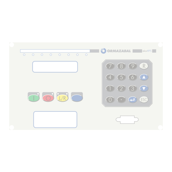
General description General instructions ekor.rps 1.4. User interface 1.4.1. Local The front board has: These pushbuttons must be pushed at least for 0.5 s to be considered active. 1. 16 key keyboard Moreover, the pushbuttons to be effective, “push- 2. 4 signaled push-buttons button enable”... -
Page 11: Hardware Configurations
5 independent inputs. b. Zero sequence voltage measurement V for the 6 outputs (4 independent, 2 with a common point). Syncrocheck function 2 analog outputs (0 to 5 mA); for other ranges please consult Ormazabal’s technical–commercial department. IG-150-EN version 04; 03/10/16... -
Page 12: Environmental Conditions
General description General instructions ekor.rps 1.6. Environmental conditions 1. Operating temperature: - 10 up to 55 °C 2. Storage temperature: - 40 up to 85 °C 3. Relative humidity: Up to 95 % without condensation 1.7. Tests 1.7.1. Electrical tests 1. Measurement of dielectric rigidity: Acc. to/IEC 255-5, 7. -
Page 13: Wiring Diagrams
General instructions General description ekor.rps 1.9. Wiring diagrams All the following wiring diagrams show one of the possible In the outputs with change-over contact the common point digital input and output programming (very simple). See is the middle one. all the possibilities in “programming of digital inputs” and Phase sequence order is settable by keyboard/display “programming of digital outputs”... - Page 14 General description General instructions ekor.rps Power Supply Vdc T6 (VA) General trip DC/DC T7 (VB) Close T8 (VC) Phase trip Ground trip Free Free T1 (IA) HW status T2 (IB) T3 (IC) T4 (IN) T5 (INS) OPTIONAL SD1 0 SD1 1...
- Page 15 General instructions General description ekor.rps Power Supply Vdc T6 (TA) General trip DC/DC T7 (TB) Close T8 (TC) Phase trip Ground trip OPTIONAL T9 (SYN) Free Free T1 (IA) HW status T2 (IB) T3 (IC) T4 (IN) OPTIONAL T5 (INS)
- Page 16 General description General instructions ekor.rps Power supply Vdc T6 (TA) DC/DC General trip T7 (TB) Close T8 (TC) Phase trip Neutral trip Free Free Optional HW state T9 (SYN) OPTIONAL SD10 SD11 SD12 SD13 T1 (IA) SD14 T2 (IB) T3 (IC)
- Page 17 General instructions General description ekor.rps Power supply Vdc General trip T6 (TA) DC/DC Close T7 (TB) Phase trip T8 (TC) Neutral trip Not configured Not configured Optional HW status T1 (IA) SD10 T2 (IB) SD11 T3 (IC) SD12 T4 (IN)
- Page 18 General description General instructions ekor.rps Power supply Vdc T6 (VA) General trip DC/DC T7 (VB) Close T8 (VC) Phase trip Neutral trip T9 (I0) polarization Not configured Not configured HW status SD1 0 T1 (IA) SD1 1 T2 (IB) SD1 2...
- Page 19 General instructions General description ekor.rps Power supply Vdc T6 (VA) DC/DC General trip T7 (VB) Close T8 (VC) Phase trip Neutral trip T9 (V0) Not configured Not configured HW status T1 (IA) SD10 T2 (IB) SD11 T3 (IC) SD12 T4 (IN)
- Page 20 General description General instructions ekor.rps Power supply Vdc T6 (VA) General trip DC/DC T7 (VB) Close T8 (VC) Phase trip Neutral trip T9 (I0) polarization Not configured Not configured HW status T1 (IA) SD10 T2 (IB) SD11 T3 (IC) SD12...
- Page 21 General instructions General description ekor.rps Power supply Vdc T6 (VA) General trip DC/DC T7 (VB) Close T8 (VC) Phase trip Neutral trip T9 (I0) polarization Not configured Not configured HW status SD10 T1 (IA) SD11 T2 (IB) SD12 T3 (IC)
- Page 22 General description General instructions ekor.rps Power supply Vdc T6 (VA) DC/DC General trip T7 (VB) Close T8 (VC) Phase trip Neutral trip T9 (VSYNC) Not configured Not configured HW status SD10 T1 (IA) SD11 T2 (IB) SD12 T3 (IC) SD13...
- Page 23 General instructions General description ekor.rps Power supply Vdc T6 (VA) DC/DC General trip T7 (VB) Close T8 (VC) Phase trip Neutral trip Not configured Not configured HW status T9 (VSYNC) OPTIONAL SD10 T1 (IA) SD11 T2 (IB) SD12 T3 (IC)
- Page 24 General description General instructions ekor.rps Power supply Vdc T6 (VA) DC/DC General trip T7 (VB) Close T8 (VC) Phase trip Neutral trip T9 (VSYNC) Not configured Not configured HW status SD10 T1 (IA) SD11 T2 (IB) SD12 T3 (IC) SD13...
- Page 25 General instructions General description ekor.rps Power supply Vdc T6 (VA) General trip DC/DC T7 (VB) Close T8 (VC) Phase trip Neutral trip T9 (VSYNC) Not configured Not configured HW status SD10 T1 (IA) SD11 T2 (IB) SD12 T3 (IC) SD13...
- Page 26 General description General instructions ekor.rps Special Models Some special models only have its functionality as special. For example, the wiring diagram of E1 type models is the same as that of NC family. Power supply Vdc T6 (VA) General trip...
- Page 27 General instructions General description ekor.rps Sometimes, the units can be used with wiring different to those indicated. Examples: Power supply Vdc General trip T6 (VA) DC/DC Close T7 (VB) Phase trip T8 (VC) Neutral trip Not configured T9 (V0) Not configured...
- Page 28 General description General instructions ekor.rps Power supply Vdc General trip DC/DC Close Phase trip Neutral trip Instantaneous trip Unbalance trip HW status Trip direction 52 status Trip coil 52 close supervision Trip coil 52 open supervision Close coil 52 close supervision Close coil 52 open supervision Not configured...
- Page 29 General instructions General description ekor.rps Power supply Vdc T6 (TA) General trip DC/DC T7 (TB) Close T8 (TC) Phase trip Neutral trip T9 (SYN) Sensitive neutral trip Not configured T1 (IA) HW status T2 (IB) T3 (IC) T4 (IN) T5 (INS)
- Page 30 General description General instructions ekor.rps Connections of the analogue inputs in models with The terminal numbers indicated in the previous wiring closed type terminals: diagrams is for units with pin type terminals. If the units have closed type terminals, the only difference lies on those...
- Page 31 General instructions General description ekor.rps Connection of the extension cards (optional) SD10 SD10 SD11 SD11 SD12 SD12 SD13 SD13 SD14 ED10 ED10 ED11 ED11 ED12 ED12 ED13 ED13 ED14 ED15 ED16 ED17 Figure 1.20. 9 digital inputs (DI) + 7 digital outputs (DO) Figure 1.21.
- Page 32 General description General instructions ekor.rps Figure 1.22. Blocks diagramm IG-150-EN version 04; 03/10/16...
-
Page 33: Hardware
General instructions Hardware ekor.rps Hardware 2.1. Constructive characteristics. Horizontal box (ekor.rps-h) Figure 2.1. Unit’s external dimensions [mm] Figure 2.2. Panel cut-off in mm IG-150-EN version 04; 03/10/16... -
Page 34: Constructive Characteristics (Ekor.rps-Tcp)
Hardware General instructions ekor.rps 2.2. Constructive characteristics (ekor.rps-tcp) Figure 2.3. Unit’s external dimensions [mm] Figure 2.4. Panel cut-off in mm IG-150-EN version 04; 03/10/16... -
Page 35: Rear Terminals
General instructions Hardware ekor.rps 2.3. Rear terminals Figure 2.5. Standard (all for pin type terminals) Figure 2.6. Option with closed type terminals for analog inputs IG-150-EN version 04; 03/10/16... -
Page 36: Options For Rear Communications Ports
Hardware General instructions ekor.rps 2.4. Options for rear communications ports OF (glass or plastic) RS-485 RS-232 Figure 2.7. Single port OF + OF RS-485+RS-232 RS-232+RS-232 OF+RS232 Ethernet OF + OF Figure 2.8. Double port IG-150-EN version 04; 03/10/16... - Page 37 General instructions Hardware ekor.rps Ethernet RJ45+ OF Eth.RJ45+RS232 Eth.RJ45+RS485 Figure 2.9. Ethernet IG-150-EN version 04; 03/10/16...
-
Page 38: Rs485 Connection Detail Between
Computer Screen Network end R 120 Ohms DB9 Female type rear connector (in the unit) Screened twisted pair Last unit ekor.rps unit Rest of DB9 connector terminals without inner connection Figure 2.10. RS485 connection IG-150-EN version 04; 03/10/16... -
Page 39: Connection Between Fiber Optic And A Radio Modem
General instructions Hardware ekor.rps 2.6. Connection between fiber optic and a radio modem The contact of the ekor.rps protection is made by programming a digital output such as “RTS control”. ekor.rps FO/RS232 converter Radio RTS (contact) + 12 V (aprox) Figure 2.11. Connection between fiber optic... -
Page 40: Ethernet Communication
Hardware General instructions ekor.rps 2.7. Ethernet communication 2.7.1. Ethernet via GOF The optic channels characteristics are the following: 12. The maximum transmission distance is calculated as follows: 1. Baud rate: 100 Mb − − 2. Connector: ST 3. Optical transmitter: LED where: PP = Losses in the link 4. -
Page 41: Technical Characteristics
General instructions Hardware ekor.rps 2.8. Technical characteristics 2.8.1. Power Supply 1. Models with 24 – 48 V 3. Consumption: 8 W minimum a. Operating range: 18 up to 60 V 18 W maximum 2. Models with 125 – 220 V a. Operating range: 86 up to 280 V 2.8.2. Output Contacts Relays 1 to 6 and 8 to 13: Relays 7 to 14: 1. -
Page 42: Irig-B Input
Connections: IRIG-B generator Screen Twisted and shielded pair ekor.rps unit Figure 2.14. IRIG-B input The input circuit is a 390 Ω serial resistance with an The number of units that can be connected in parallel to optoacoplator; for a 5 V signal, the approximate consumption a generator depends on its capacity of supplying output is 10 mA. -
Page 43: Analog Outputs
Continuous: 20 A b. For 1 second: 500 A (1 s) 2.8.10. Voltage circuits 1. Thermal capacity ekor.rps units preferably have standard a. Continuous: 2 U rating current circuits. As an option and b. For 1 second: 5 U when confirmed by Ormazabal’s technical–... -
Page 44: Measurements Accuracy
Hardware General instructions ekor.rps 2.8.11. Measurements accuracy 1. Current 2. Voltage Measurement range: (0 a 1.2*I Accuracy: 0.5 % of the rated voltage U up to 1.2*V For I = 1: Class 1 (1 % of I 3. Phase difference angles Accuracy: ±... -
Page 45: Unit Configuration
General instructions Unit configuration ekor.rps Unit configuration The settings that are defined next configure the unit, for All of them are of single table (table 0). By keyboard/display what they are basic. you access the programming of the table 0 through the menu “change settings”... -
Page 46: Programming Of Digital Outputs
Unit configuration General instructions ekor.rps Select. NO/NC. It defines if the input must be interpreted A logical input is a virtual (not physical), the state of which like active when it is viewed closed or when it is viewed depends on the state of the corresponding logical input open. -
Page 47: Programming Of Leds
General instructions Unit configuration ekor.rps 3.3. Programming of LEDs Through console, it is carried out in the screen “LEDs The proceedings are totally analogous to the programming programming”. of digital outputs, except that the activation time is not programmed and that the possible types are “memorized”... -
Page 48: Setting Ranges (Table 0, Single)
Unit configuration General instructions ekor.rps The following setting is only available via the keypad/ *1.2*6. display in IRIG-B format (at the same level as PROG.TABLE 0): 5. [Q (reactive power)], secondary absolute value Q. Full scale 3*V *1.2*6. “IRIG-B format”: determines if the year in the IRIG 6. -
Page 49: Communication Configuration
Communication via front door (Port 1_1) and rear port Nr. 2 (Port 1_2) (COM 1) The ekor.rps unit has an address identifying number, which If the ekor.rps unit is replaced by another one, the installed makes possible to identify the messages sent to the unit, unit must have the same address as the removed one. - Page 50 General instructions ekor.rps MODBUS If the ekor.rps unit is replaced by another one, the installed unit must have the same address as the one removed. If the chosen option is MODBUS, the address is programmable They are also programmable the baud rate, the parity and from the keyboard/display, entering “CHANGE SETTINGS”,...
-
Page 51: Ethernet Communication
General instructions Unit configuration ekor.rps 3.5.3. Ethernet communication The signals received from relay 1 and relay 2 arrive at It is only used in models with an Ethernet port. the control signals “Signal i relay 1” and “Signal i relay 2”, To configure the Ethernet port, the first parameter to where i goes from 1 to 8. -
Page 52: Other Configuration Settings
It should not be used by the user. 3.6.6. Test mode The test mode is to be used by Ormazabal’s technical– commercial department exclusively, following a specific procedure. It must not be used by the user. -
Page 53: Push-Buttons/Leds Enabling And Locking
General instructions Unit configuration ekor.rps 3.6.7. Push-buttons/LEDs enabling and locking by command Under the title “PUSH-BUTTONS” there are two settings: “ENAB.COMMAND LOC” (Enable blocking/unblocking by command): If this setting is at “YES”, the programmed “ENAB. PUSH-BUTTON” (enable push-buttons): If this setting protection function blocking/unblocking control commands is at “COMMAND”, the front plate command push-buttons... -
Page 54: Protection Functions. Description And Settings
Protection functions. Description and settings General instructions ekor.rps Protection functions. Description and settings 4.1. Phase overcurrent protection 4.1.1. General description Three-phase overcurrent protection, with the next selectable characteristics (function 5051): Timed characteristic Instantaneous characteristic 1. Inverse normal time( I BSC or I ANSI)) 1. -
Page 55: Timing Cancellation
General instructions Protection functions. Description and settings ekor.rps Working with curve, the time to trip depends on the the selected curve (family and index) and o the current. selected curve (family and index) and the current value. If the selected curve is definite time, the pickup will drop... -
Page 56: Settings Ranges Of The Instantaneous Characteristic (High Level) (6 Tables)
Protection functions. Description and settings General instructions ekor.rps 4.1.5. Settings ranges of the instantaneous characteristic (high level) (6 tables) Setting Step Notes Enable YES/NO/pick up Phase instantaneous trip [A] 0.02 40.00 0.01 With standard ratings 200.0 0.01 With specified ratings Additional time [s] 0.00... -
Page 57: Setting Range Of Neutral Time Inhibition
General instructions Protection functions. Description and settings ekor.rps 4.2.3. Setting range of neutral time inhibition (6 tables) Setting Step Notes Limit current [A] 200.0 Table 4.5. Setting range of neutral time inhibition The neutral time inhibition setting allows the inhibition that is, the curve turns into a horizontal line from this value. -
Page 58: Instantaneous Special Operation
Protection functions. Description and settings General instructions ekor.rps 4.3. Instantaneous special operation The settings corresponding to the phase, neutral and It is enabled at “NO”; the instantaneous is disable under any sensitive neutral instantaneous (only in the low level), are condition. - Page 59 General instructions Protection functions. Description and settings ekor.rps Figure 4.2. Option timing after closing Option “Timing after closing”. After any closing (manual or fixed time” instead of using the normal “additional time. This automatic), if the corresponding mask in the trip permission time can be 0, in order to act as a true instantaneous.
-
Page 60: Nd Harmonic Restraint
Protection functions. Description and settings General instructions ekor.rps 4.4. 2 harmonic restraint It locks the first level of the units 51, 50, 51N, 50N and 46 In order to deactivate the locking, the following conditions (time and instantaneous unbalance). For 50/51 units, must be fulfilled: restraint is available for a single phase or for all phases. -
Page 61: Directionality Of The Phase And Neutral Overcurrent Protections
General instructions Protection functions. Description and settings ekor.rps The settings (6 tables) are: Setting Step Notes Module enable K module constant 0.01 Angle enable Angle The settings are located in the console in the “2 harmonic restraint” and “manual closing protection blocking” screens. -
Page 62: Phase Directional In Quadrature (67)
Protection functions. Description and settings General instructions ekor.rps Trip permission without V (Directional Locking on the to be added 5° at each side to obtain the locking zone. In display). If it is set as YES allows the overcurrent trip if the... -
Page 63: Phase Directional By Sequences (67)
General instructions Protection functions. Description and settings ekor.rps 4.6.2. Phase directional by sequences (67) Operation Negative sequence directional Positive sequence directional The direction is determined comparing the negative The direction is determined comparing the positive sequence voltage and current, being I higher than a sequence voltage and current. -
Page 64: Neutral Directional (67N); Polarization By S
Protection functions. Description and settings General instructions ekor.rps Memory Signalling It is polarized by the positive sequence voltage while it is It provides forward and reverse signaling. If the direction higher than a threshold. If the voltage is lower than this is forwards, the signals “Forward A”, “Forward B”... -
Page 65: Neutral Directional (67N); Polarization By S - (V )
General instructions Protection functions. Description and settings ekor.rps Trip permission without V (Directional Locking on the Signaling display) It provides forward and reverse signaling. This setting is used when the polarization voltage (3 V ) falls Being the trip permission without V... -
Page 66: Neutral Directional (67N); Polarization By S + S
Protection functions. Description and settings General instructions ekor.rps 4.6.5. Neutral directional (67N); polarization by S + S - (V + V Operation with polarization by V and V Signaling The direction is determined regardless of the previous It provides forward and reverse signaling. The directional criteria. -
Page 67: Neutral Directional (67N); Polarization By S - + I
General instructions Protection functions. Description and settings ekor.rps 4.6.7. Neutral directional (67N); polarization by S + I (V + I Operation Signaling The direction is determined regardless of the previous It provides forward and reverse signaling. The directional criteria (V and I). If any of them determines that the units output is an OR of the polarization by voltage and direction is the trip direction, the trip permission is given. -
Page 68: Neutral Directional (67N); Polarization By S + S- + I
Protection functions. Description and settings General instructions ekor.rps 4.6.9. Neutral directional (67N); polarization by S + S- + I (V + V2 + I Operation Signaling The direction is determined regardless of the previous It provides forward and reverse signaling. The directional criteria (V , ... - Page 69 General instructions Protection functions. Description and settings ekor.rps 4.6.10. Neutral directional (67N); watimetric directional 4. For backwards faults the angle between the current It is used for lines with compensations by means of Petersen coil. and the voltage, displaced the maximum torque angle, and must be between 277 and 83.
-
Page 70: Neutral Directional (67N); I*Cos (Φ)/I*Sen (Φ) Directional
Protection functions. Description and settings General instructions ekor.rps 4.6.11. Neutral directional (67N); I*cos (φ)/I*sen (φ) directional An input (“67N Isen (j) or Icos (j)”) can be programmed setting: If it is deactivated the algorithm I*cos (j) is carried and when it gets activated the I*cos (j) operation mode out and if it is activated, the I*sen (j), regardless the setting. - Page 71 General instructions Protection functions. Description and settings ekor.rps As the neutral units allow the trips with forward and reverse faults the characteristics will have the following form: Backwards Forwards Figure 4.12. Trip with forward and reverse faults I*sen (φ) directional In order to allow the pick up of the directional unit, the 3.
-
Page 72: Sensitive Neutral Overcurrent Protection
Protection functions. Description and settings General instructions ekor.rps 4.7. Sensitive neutral overcurrent protection 4.7.1. General description Sensitive neutral overcurrent protection, with the same (except that there is only one instantaneous element), and possible characteristics as the ones described for phases independent settings (function 50Ns/51Ns). -
Page 73: Directionality
General instructions Protection functions. Description and settings ekor.rps 4.7.4. Directionality In case the model has the “neutral directional” and the The directional watrimetic and the cosine type directional “sensitive neutral” units, the later can also be directional, are almost the same, with the only difference that one is set for which it has the “torque control”... - Page 74 Protection functions. Description and settings General instructions ekor.rps Watimetrical directional It is use for those lines with compensation via Petersen coil. 3. For backwards faults, the angle between the current and the voltage, displaced the maximum torque angle, In order to allow the directional unit pickup, the following and must be between 277 and 83 must be fulfilled.
- Page 75 General instructions Protection functions. Description and settings ekor.rps I*cos (φ)/I*sen (φ) directional It works as a torque control of the neutral sensitive unit. 3. For forwards faults the angle between the current and the voltage, displaced the maximum torque angle, and It has an input (“67NS Isen (j) or Icos(j)”), twhich when it must be between 97 and 263.
- Page 76 Protection functions. Description and settings General instructions ekor.rps As the sensitive neutral units allow the trip with forwards and backwards faults, the characteristics will be as follows. Backwards Forwards Figure 4.16. Forwards faults and backwards faults I*sen (φ) directional In order to allow the picking up of the directional unit the 3.
-
Page 77: Current Unbalance Protection
General instructions Protection functions. Description and settings ekor.rps 4.8. Current unbalance protection 4.8.1. General description It contains the timed and instantaneous unbalance It must be taken into account that the phase protection functions. sequence A-B-C or C-B-A is programmable, so that the I depends on that setting. -
Page 78: Broken Conductor Protection
Protection functions. Description and settings General instructions ekor.rps 4.9. Broken conductor protection 4.9.1. General description It is a definite time protection unit. The starting value which The relay trips when the programmed time has expired is set is, in per unit, the module ratio between the negative since the starting setting value is exceed. -
Page 79: Mode 2 (51 V)
General instructions Protection functions. Description and settings ekor.rps 4.10.2. Mode 2 (51 V) IWhen the control voltage is lower than the control voltage The settings are the following: (one programmed value), the effective settings of the 1. Enable control by voltage: YES/NO (as it has been said function 51 stop being the programmed in "phase time... -
Page 80: High Current Lockout
Protection functions. Description and settings General instructions ekor.rps 4.11. High current lockout 4.11.1. Description There are two other instantaneous settings groups, one If they give a trip, it will be moved on to definitive trip’ for phases and other for neutral (not for sensitive neutral). -
Page 81: Settings (Table 0, Single)
General instructions Protection functions. Description and settings ekor.rps 4.12.2. Settings (table 0, single) 3. Operating time of “cold load” settings: 0.1 to 3600 s They are accessible through keyboard/display in "table 0" - " special protections" - "cold load" , or through console on the (1 hour) with 0.01 s resolution in console “duty time”. -
Page 82: Isolated Neutral Protection
Protection functions. Description and settings General instructions ekor.rps 4.13. Isolated neutral protection 4.13.1. General description The “Directional zero sequence relay” incorporated in the They are settable parameters relay carries out a directional protection against earth faults 1. Enable. If it is set to YES allows the protection units in isolated neutral systems (67IN function). -
Page 83: Overvoltage Protection
General instructions Protection functions. Description and settings ekor.rps 4.14. Overvoltage protection 4.14.1. General description Three-unit overvoltage protection, which can be simples 6. Very inverse special time (MIEs BSC) or compounds (see “General settings”), with following 7. Moderately inverse time (ANSI) selectionable characteristics to choose from (function 59): 8. -
Page 84: Setting Ranges Of The Timed Characteristic
Protection functions. Description and settings General instructions ekor.rps 4.14.3. Setting ranges of the Instantaneous characteristic (6 tables) Setting Step Notes Enable YES/NO Phase instantaneous trip [V] Additional time [s] 0.00 60.00 0.01 Table 4.17. Setting ranges of the Instantaneous characteristic (6 tables) These settings can be found in the console on the screen “voltage protection”. -
Page 85: Setting Ranges Of The Instantaneous Characteristic (6 Tables)
General instructions Protection functions. Description and settings ekor.rps These settings can be found in the console on the screen Working with curve, the tripping time depends on the “voltage protection”. selected curve (family and index) and on the voltage value. -
Page 86: Instantaneous Characteristic
Protection functions. Description and settings General instructions ekor.rps 4.16.2. Instantaneous characteristic It is a definite time protection unit. It only checks if the phase order is the programmed one or the opposite one. In the case that the order is opposite to the programmed one it will trip after a programmed time. -
Page 87: Setting Range (6 Tables)
General instructions Protection functions. Description and settings ekor.rps 4.17.1. Setting range (6 tables) Setting Step Notes Enable YES/NO (see note) Pick up [V] Curve type Definite time Normal inverse curve Short inverse time Long inverse time Very inverse curve Extremely inverse curve... -
Page 88: Minimum Frequency
Protection functions. Description and settings General instructions ekor.rps 4.18.1. Minimum frequency Lockings Each step picks up if the frequency is below the set value during a number of cycles equal or higher than the setting “Nr. of pickup cycles”. Once it picks up, the programmed If the voltage in phase B is lower than the setting “Minimum... - Page 89 General instructions Protection functions. Description and settings ekor.rps The algorithm stores the periods of the last 5 cycles of the For the unit to pickup, the frequency derivative must be signal and calculates the frequency derivative comparing exceeded in module during the set number of cycles minus the frequency measurement of the present cycle with the 4 cycles.
-
Page 90: Fuse Failure
Protection functions. Description and settings General instructions ekor.rps Lockings The frequency derivative units are locked by: 2. Minimum supervision voltage. If the voltage in phase B is lower than the setting, the pickup of the frequency 1. Minimum supervision current. If the minimum current derivative unit’s pickup is not allowed. -
Page 91: Teleprotection
General instructions Protection functions. Description and settings ekor.rps 4.20. Teleprotection 4.20.1. Operation It is based upon the use of teleprotection signals between 2. Permission scheme: The signal received gives both end terminals of the line. The effect upon the output permission for an instantaneous trip within the relays’... -
Page 92: Protection Trip Mask (6 Tables)
Protection functions. Description and settings General instructions ekor.rps 4.20.3. Protection trip mask (6 tables) This setting can only be programmed using a PC, not by Trip causes set as “YES” at “blocked” mask, give a trip keyboard/display. with acceleration by blocking logic, only if locking logics (Directional Locking) are selected in trip logic settings. - Page 93 General instructions Protection functions. Description and settings ekor.rps Notes main pilot protection schemes Permissive underreach (PUTT) When “Directional Locking” scheme is set or “Inverse Directional Locking” function is enabled zone 3 must be set Pilot protection signal (ETP) is sent with the activation of as REVERSE.
- Page 94 Protection functions. Description and settings General instructions ekor.rps Directional Locking Pilot protection instantaneous trip with activation of zone 2, ETP locking signal is sent if the fault is seen backwards Z3(R) if RTP signal is not received, once the locking time is elapsed MEM.
- Page 95 General instructions Protection functions. Description and settings ekor.rps Figure 4.28. Directional unlocking Additional pilot protection schemes Reverse direction locking It is used on double-circuit lines in order to prevent the The figure shows a flow scheme when the fault occurs and immediate tripping of a protection that is seeing a fault when the breaker is opened.
-
Page 96: Thermal Image
Protection functions. Description and settings General instructions ekor.rps It is used in the permissive schemes (overreach, underreach The teleprotection signal is sent with either of the following and directional unlocking). conditions: The pilot protection instantaneous trip is the one 1. According to the selected scheme corresponding to the selected scheme. -
Page 97: Settings
General instructions Protection functions. Description and settings ekor.rps 4.21.2. Settings Setting Step Notes Enable YES/NO Heating time constant [min] Cooling time constant [min] Threshold alarm [%] Threshold restore [%] Rated current [A] 200.0 0.01 Table 4.27. Settings 4.21.3. Trip times Figure 4.32. -
Page 98: Heating Curves
Protection functions. Description and settings General instructions ekor.rps 4.21.4. Heating curves The heating curve is calculated from the following formula: The next figure gives as an example, the heating curves, with 3 min time constant, for I/I = 1 and for I/I = 2. -
Page 99: Field Loss Protection
General instructions Protection functions. Description and settings ekor.rps 2. Lets suppose that during 200 s it is heated with I/I Combined examples cooling and heating: = 0.5, then with I/I = 1.5 until reaching 100 %, where it trips, 1. Let’s suppose that during 200 s it is heated with I/I... -
Page 100: Mho Area Settings Range
Protection functions. Description and settings General instructions ekor.rps 4.22.3. MHO area settings range Setting Step Notes Z1A impedance setting (offset) [Ω] -20.0 20.0 Z1B impedance setting (diameter) [Ω] 120.0 Area 1 undervoltage monitoring YES/NO Area 1 alarm time setting [s] 10.0... -
Page 101: Power Protection
General instructions Protection functions. Description and settings ekor.rps 4.23. Power protection 4.23.1. General From the current and voltage measurements, the protection This setting is the Console, in the Power protection screen calculates the active and reactive power and the power as, “Power Nominal Current (A)”, and in the keyboard/display... -
Page 102: Maximum Power Protection
Protection functions. Description and settings General instructions ekor.rps 4.23.3. Maximum power protection General description It protects against excessive increases in the generated power. The operation is similar to the previous. The protection will trip the corresponding relay when the generated active power is greater than the set value. -
Page 103: Reactive Power Reverse Protection
General instructions Protection functions. Description and settings ekor.rps 4.23.5. Reactive power reverse protection General description The protection acts when the reactive power flux is reversed (field loss in generators) and this exceeds the set value. In this situation, the protection will trip the relay or relays programmed for it. -
Page 104: Maximum Apparent Power Protection
Protection functions. Description and settings General instructions ekor.rps 4.23.7. Maximum apparent power protection General description It is a protection against excessive increases in the generated power. The operation is similar to the previous. The protection will trip the corresponding relay when the generated apparent power is greater than the set value. -
Page 105: Setting Range (6 Tables)
General instructions Protection functions. Description and settings ekor.rps 4.24.2. Setting range (6 tables) Setting Step Notes Excessive Nr. of trips Time span for excessive Nr. of trips [s] 3.600 Trip circuit monitoring enable YES/NO Close circuit monitoring enable YES/NO ∑kI alarm threshold 65.535... -
Page 106: Coil Monitoring Example
Protection functions. Description and settings General instructions ekor.rps 4.25. Coil monitoring example 4.25.1. General description Trip sealing: If it is set to "YES" when a tripping signal is sent, The open and close failure timings provide the time margin this signal remains until it sees the circuit breaker opening, existing between the corresponding command and the signal even if the current has disappeared. -
Page 107: Setting Range (6 Tables)
4.29.1. Introduction The fault locator for singles lines implemented with the 2. Impedance parameters of the line on which the fault ekor.rps protection processes the information collected on has occurred. each fault, thereby returning the estimated distance to the 3. Length of the line. -
Page 108: Programming Settings And Collecting Results
Protection functions. Description and settings General instructions ekor.rps 4.29.2. Programming settings and collecting results The necessary parameters for the distance calculation algorithm to work are the following (all the values are referred to the primary): Abbrev. Description Units Line length W/km Real part of the line’s positive sequence Impedance per length unit... -
Page 109: Locator Operation
General instructions Protection functions. Description and settings ekor.rps The parameters with the transformation ratios of CT and VT The result of the distance calculation is included in the fault are communicated to the relay from the general settings report as indicated in the following figure: screen included in the following figure: Figure 4.41. - Page 110 Protection functions. Description and settings General instructions ekor.rps Pre-fault and post-fault filtering Distance Calculation The distance calculation algorithm uses the basic The distance calculation algorithm developed for the single components of the voltage and current waves. The filtering line has been designed for a line topology such as the extracts the said components from the signals stored at the following figure.
- Page 111 General instructions Protection functions. Description and settings ekor.rps Presentation of results The presentation of results is made in different ways: 5 mA 1. In the display. In the “last fault” submenu. 2. In the fault report that is sent to the PC by communication.
-
Page 112: Automation Functions
Automation functions General instructions ekor.rps Automation functions 5.1. Recloser 5.1.1. General description 4. Definitive trip status. The unit enables up to 4 reclosings. The recloser’s final situation when it has executed all of the Different close times for phase to phase and phase to earth programmed attempts and the breaker remains open, given faults. -
Page 113: Operation
General instructions Automation functions ekor.rps 5.1.2. Operation The figures below represent the sequence of events for a recloser which has been programmed for three reclosing attempts, with TR1, TR2 and TR3 as the corresponding reclosing times, with a reclaim Tsec, for different situations: 1. - Page 114 Automation functions General instructions ekor.rps 2. Second successful reclosing. Figure 5.3. Second successful reclosing Third successful reclosing. Figure 5.4. Third successful reclosing 4. Moves onto a definitive trip after exhausting the programmed number of reclosings. Figure 5.5. definitive trip number of reclosings 5.
-
Page 115: Setting Range (6 Tables)
General instructions Automation functions ekor.rps 5.1.3. Setting range (6 tables) Setting Step Notes Recloser in service YES/NO Number of closures Waiting time for the first closure, phase to phase faults [s] 0.05 600.0 0.01 Waiting time for the second closure, phase to phase faults [s]... -
Page 116: Other Operation Characteristics
Automation functions General instructions ekor.rps 5.1.6. Other operation characteristics 1. Recloser out of service b. Recloser locked. Active if the recloser is disengaged or if the external recloser locking input is activated. This state is reached by pressing the push-button R on the c. -
Page 117: Reclosing After Tripping
General instructions Automation functions ekor.rps 5.3. Reclosing after tripping by minimum frequency 5.3.1. General description After a trip by minimum frequency, if the function is enabled If the “definitive tripping waiting time” has elapsed and the and not locked, the unit tries only one reclosing. -
Page 118: Special Recloser To Operate With Protections With Single-Pole Trip
If the first trip is single-pole, the closure time and the reclaim time can be different of those for the three-pole a. The ongoing cycle will start by actuation of the ekor.rps trip (other settings) and the close command (which is itself or by activation of the “three-pole trip”... -
Page 119: Settings
General instructions Automation functions ekor.rps 2. Synchronism permission. It is given permission if We stress that this permission is referred only to the synchrocheck function; so she is only the one that controls during a programmable time, the following conditions the “closure permission”... -
Page 120: Automation Function For Distribution
Automation functions General instructions ekor.rps 5.7. Automation function for distribution substations 5.7.1. Unloaded springs automation functions 1. It is composed of: signal is generated and a timer starts according to "spring loading time" setting. If before exceeding this time the input a. -
Page 121: Other Settings
General instructions Other settings ekor.rps Other settings 6.1. Programming of logic outputs The user can configure up to 15 logic outputs, called "logic As it can be observed in the definition of a logic output 1" to "logic 15", which can be assigned to relays, as well... -
Page 122: Selectivity Logic Functions
Other settings General instructions ekor.rps The pulse time (duration) is the time during which the logic signal remains active. Its programming allows two options: 1. "By logic": After the delay, the output is active as long as there is a 1 at the programmed logic output. -
Page 123: Data Acquisition Functions
General instructions data acquisition functions ekor.rps data acquisition functions 7.1. Events reports 2. Current protection The list of events which can be generated by the protection (if it has the corresponding functions, which are optional in a. Timed unit pickup phase A many cases) is indicated as follows. -
Page 124: Fault Records
General instructions ekor.rps 3. Overvoltage protection: b. Deactivation of digital input xx (1 to 17) 6. Recloser a. Timed unit pickup phase A b. Timed unit pickup phaseB a. External locking of the recloser c. Timed unit pickup phase C b. -
Page 125: Measurements
General instructions data acquisition functions ekor.rps The 4 fault currents are simultaneous, and they are the ones Besides they are kept in non volatile memory, and they are existing at the moment of the trip order. retrievable through keyboard /display, the following data corresponding to the last 10 faults: 1. -
Page 126: Measurements At The Primary
General instructions ekor.rps 7.3.2. Measurements at the primary By keyboard/display Through PC (protections console) 1. They are on the first of the "measurements" screens Phase A current (in amperes) 2. Phase A current (module in amperes and angle in 1. -
Page 127: Measurements Historical Report
General instructions data acquisition functions ekor.rps 7.4. Measurements historical report 7.4.1. General description The protection keeps in non volatile memory a queue of the accumulated value is divided into the window number 400 historical measurement records, retrievable from a PC of seconds, in order to obtain he average value. -
Page 128: Protection Status
General instructions ekor.rps 7.6. Protection status 7.6.1. By keyboard/display It can be seen: 1. Date and time of the relay 2. Status of each of the digital inputs: Open (A) or closed (C) 7.6.2. Through PC (protections console) On the "status"... -
Page 129: Other Functions
General instructions Other functions ekor.rps Other functions 8.1. Time setting and synchronization 8.1.1. Time setting It can be done from the keyboard/display (within "change settings") or from the protection console (screen 1 "status"). 8.1.2. Synchronization There is an input for synchronization demodulated by it shows corresponds to PPS (Pulse per second) coinciding IRIG-B demodulated (see section “IRIG-B input”... - Page 130 Other functions General instructions ekor.rps Nr. Bytes Format Specification Data Word PROCOME * 1.2 module Word PROCOME * 1.2 module Word PROCOME * 1.2 module Word PROCOME * 1.2 module AVERAGE Word PROCOME √3*V * 1.2 module (compound voltage) Word PROCOME √3*V...
- Page 131 General instructions Other functions ekor.rps Continuation N° Bytes Formato Specification Data Word PROCOME * 1.2 Zero sequence voltage Word PROCOME * 1.2 Positive sequence voltage Word PROCOME * 1.2 Negative sequence voltage Word PROCOME 100 (%) Distance to fault Word PROCOME 100 (°)
- Page 132 Other functions General instructions ekor.rps The background scale indicated corresponds to a count Therefore, in the worst case scenario, where only one signal number of 4095. changes in each queue record, the queue contains the latest 400 digital changes occured in the equipment. This number...
- Page 133 General instructions Other functions ekor.rps Continuation Action Default (in PROCOME) Neutral time locking H2 (2 group) programmable not programmed Neutral time unlocking H2 (2 group) programmable not programmed Sens. Neutral instant. locking H2 (2 group) programmable not programmed Sens. Neutral instant. unlocking H2 (2...
- Page 134 Other functions General instructions ekor.rps Continuation Action Default (in PROCOME) Output 4 permanent act programmable not programmed Output 5 permanent act programmable not programmed Output 6 permanent act programmable not programmed Output 7 permanent act programmable not programmed Output 8 permanent act...
-
Page 135: Mando Local/Remoto
General instructions Other functions ekor.rps Continuation Action Default (in PROCOME) Protection functions unblocking Command 1 Command 2 Command 3 Command 4 Command 5 Command 6 Command 7 Command 8 Table 8.2. Command orders So that the locking/unlocking commands to be effective, they must be enabled by setting (see unit configuration–enabling pushbuttons and lockings by commands). -
Page 136: Commands By Keyboard And Front Push-Buttons
Other functions General instructions ekor.rps 8.4. Commands by keyboard and front push-buttons keyboard/display “pushbuttons”-“enab. Push-button type row (confirmation) can be programmed pushbuttons”, “functionals” has been programmed; at “NO”, so the command is immediately executed, or at commands can be executed from the keyboards and from “YES”, so confirmation is requested via display which is... -
Page 137: Temperature Supervision
General instructions Other functions ekor.rps 8.7. Temperature supervision 2. Temperature lower than the minimum threshold. If the This function checks that the unit temperature d is within the set margin. It generates two signals: temperature is lower than the set maximum threshold. -
Page 138: Operation Mode
Operation mode General instructions ekor.rps Operation mode 9.1. Through keyboard/display 9.1.1. Introduction The purpose of the keyboard/display is the local push-buttons, and the view of settings, measures and faults introduction to the unit of settings and commands, through through display. -
Page 139: Operating Mode
General instructions Operation mode ekor.rps 9.1.3. Operating mode General Description Change settings Up to the last level of the menus everything works in The display shown when inactive can be programmed the same way as by See settings and magnitudes (same in every display just by placing on it and pressing functions for same keys). -
Page 140: Through The Pc
9.2. Through the PC The protection relays ekor.rps can be monitored by PC. In The ekor.rps program, protection console developed by this way, it is possible to have access to a view of the system Ormazabal is named SIPCON. -
Page 141: Reception, Storage, Installation And Tests
4 mm cross-section. devices it incorporates to operate properly. The connection 10.2.3. RS232 cable connections to be used between the PC and the ekor.rps unit Case 1: A 25 pin PC output connector. Case 2: A 9 pin PC output connector. -
Page 142: Unit Addressing
10.3. Unit addressing See “Communications configuration” section. 10.4. Commissioning The ekor.rps protections are received with the default to guarantee its accuracy in all of the setting points of the settings stipulated in the factory. different parameters. However, it is convenient to test some... - Page 144 Ormazabal Subject to change Protection & without prior notice. Automation For further information, IGORRE contact Ormazabal. Spain www.ormazabal.com...
Need help?
Do you have a question about the ekor.rps and is the answer not in the manual?
Questions and answers