Table of Contents
Advertisement
Advertisement
Table of Contents

Related Manuals for INVT DBU100H Series


Summary of Contents for INVT DBU100H Series
- Page 1 DBU100H Dynamic Braking Unit...
-
Page 2: Table Of Contents
Operational manual for dynamic braking unit Content 1 Safety Precautions ......................1 1.1 Safety definition ......................1 1.2 Warning symbols ...................... 1 1.3 Safety guidelines ...................... 1 2 Inspection ..........................4 2.1 Unpacking inspection ....................4 2.2 Environment ......................4 2.3 Installation confirmation .................... -
Page 3: Safety Precautions
Operational manual for dynamic braking unit 1 Safety Precautions 1.1 Safety definition Danger: Serious physical injury or even death may occur if not follow relevant requirements Warning: Physical injury or damage to the devices may occur if not follow relevant requirements Note: Physical hurt may occur if not follow relevant requirements Qualified... - Page 4 Operational manual for dynamic braking unit Do not use any braking unit and braking resistor with loss and damaged components. High voltage DC current is present after connecting braking unit. Do not touch the braking unit, internal component and PCB with hands; otherwise the electric shock may occur.
- Page 5 Operational manual for dynamic braking unit DBU (no matter it is relative to the braking unit or not). Please install the safety fuses special for the semiconductors. Note: Do not switch on or off the input power supply of the dynamic braking unit frequently. ...
-
Page 6: Inspection
3. Check that there are no signs of water in the package and no signs of damage or breach to the DBU. If not, please contact with local dealers or INVT offices. 4. Check the information on the type designation label on the outside of the package to verify that the name plate is of the correct type. -
Page 7: Installation Confirmation
Operational manual for dynamic braking unit 2.3 Installation confirmation Check as followings after the installation: 1. Check that the load range of the input and output cables meet the need of actual load. 2. Check that the accessories of the DBU are correctly and properly installed. The installation cables should meet the needs of every component (including reactors, input filters, output reactors, output filters, DC reactors, braking units and braking resistors). -
Page 8: Installation Guidelines
Operational manual for dynamic braking unit 3 Installation Guidelines Only qualified electricians are allowed to carry out what described in this chapter. Please operate as the instructions in Safety Precautions. Ignoring these may cause physical injury or death or damage to the devices. -
Page 9: Installation Direction
The DBU should be installed on an upright position to ensure direction sufficient cooling effect. Note: DBU100H series should be installed in a clean and ventilated environment according to enclosure classification. Cooling air must be clean, free from corrosive materials and electrically conductive dust. -
Page 10: Installation Mode
Operational manual for dynamic braking unit 3.3 Installation mode DBU100H can be installed in wall (for all frame sizes) 3.4 External dimensions Figure 1 Dimensions of 60A DBU Figure 2 Dimensions of 110A-220A DBU... - Page 11 Operational manual for dynamic braking unit Figure 3 Dimensions of 320A-400A DBU Model W(mm) W1(mm) W2(mm) D(mm) H (mm) H1(mm) DBU100H-060-2 DBU100H-060-4 DBU100H-110-2 DBU100H-110-4 DBU100H-110-6 DBU100H-160-2 DBU100H-160-4 DBU100H-160-6 DBU100H-220-2 DBU100H-220-4 DBU100H-220-6 DBU100H-320-4 DBU100H-320-6 DBU100H-400-4 DBU100H-400-6...
-
Page 12: Product Name, Model Definition And Usage
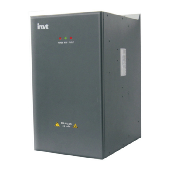
6: Applied on AC 3PH 520V(-15%)~690V(+10%) and the Max. input voltage DC1300V DBU100H series dynamic braking units are the high-performance and heavy-load dynamic braking units promoted by our company, which can brakes at the rated braking current to meet the application need in the situation of big inertia, crash deceleration and stop. When the DBU brakes, momentum will be converted into electric energy because of big inertia, and then the DC bus voltage will increase. -
Page 13: Installation Of The Dynamic Braking Unit And Parameters Setting
Operational manual for dynamic braking unit 5 Installation of the dynamic braking unit and parameters setting 5.1 Wiring diagram Figure 4 Wiring diagram of the main circuit between the dynamic braking unit and the DBU Note: The wiring between the DBU and the dynamic braking unit is less than 5m. ... -
Page 14: Main Control Terminal Of The Braking Unit
Operational manual for dynamic braking unit 5.3 Main control terminal of the braking unit Functions description: Sign Function Input terminal of the external fault. EFI-COM is defaulted to be short circuited in factory. When the external fault occurs, it will be switched off and the braking unit outputs fault signal. - Page 15 Operational manual for dynamic braking unit Serial 220V system 380V system 690V system S1 selection 1100 (Factory reserved) 1120 1140 1160 1180 1000~1110 Reserved Reserved Reserved Slave mode Slave mode Slave mode Note: If the grid voltage is above more than 20% of the normal supply, please set bigger braking voltage.
-
Page 16: Parallel Running
Operational manual for dynamic braking unit 6 Parallel running Figure 7 Wiring diagram between the parallel running braking units and the DBU Please connect the DBU, multiple braking units and the braking resistor according to figure 7. Wiring of the control terminals: when parallel braking units are put into use, the first one is the master and the others are the slaves. -
Page 17: Fault Analysis And The Solution
The fault can be indicated through LEDs. When the FAULT LED is on, it means the dynamic braking unit is abnormal. Check the faults one by one according to the information in the below table. Find the possible reasons and the solutions. If not, please contact with the local INVT office. -
Page 18: Selection
Operational manual for dynamic braking unit 8 Selection 8.1 Guidelines of braking voltage selection The setting of the braking voltage is low enough to make the DBU works around the rated voltage and ensure a safe running. Select high braking voltage can avoid misaction of the braking unit, but too high voltage has impact on the long-term running safety. -
Page 19: Usage Standard And Selection Reference Of The Input Voltage Degree For Adaptation Dbu (220V)
Operational manual for dynamic braking unit =20-40% Crane(the height of lifting is more than 100m) =5% Occasionally braking load =10% Others Basis of resistor calculation: the braking resistor needs to absorb all the regenerative electric energy of the motor. Absorbed power of the resistor(V*V/R)=The regenerative electric energy of the motor (W)= ... -
Page 20: Usage Standard And Selection Reference Of The Input Voltage Degree For Adaptation Dbu (660V)
Operational manual for dynamic braking unit 100% of the Dissipated Dissipated Dissipated adaptation power of the power of the power of the Mini braking braking braking braking allowable Power Model resistor of resistor(kW) resistor(kW) resistor(kW) braking the braking (10% of the (50% of the (80% of the resistor(Ω) -
Page 21: Selection Of The Braking Resistors
Operational manual for dynamic braking unit 100% of Dissipated Dissipated Dissipated power of the power of the power of the Mini adaptation braking braking braking allowable Power Model braking resistor(kW) resistor(kW) resistor(kW) braking resistor of resistor(Ω) (10% of the (50% of the (80% of the the braking braking) - Page 22 Operational manual for dynamic braking unit resistance to sell. Note: Parallel braking unit can enlarge the braking capacity. The braking capacity of 2 parallel braking units is two times of one braking unit. For example DBU100H-220-4=DBU100H-110-4*2。 -20-...
-
Page 23: Maintenance And Hardware Diagnostics
Operational manual for dynamic braking unit 9 Maintenance and hardware diagnostics 9.1 Maintenance intervals If installed in an appropriate environment, the dynamic braking unit requires very little maintenance. The table lists the routine maintenance intervals recommended by INVT. Checking Checking part Checking item... - Page 24 Operational manual for dynamic braking unit Checking Checking part Checking item Criterion method Note: color copper blocks Ensure there is no dust Visual change, it does and dirtiness examination not mean that there something wrong with the features. Ensure that there is no distortion Visual color-changing of the...
- Page 25 Ensure whether there is stuff foreign Visual Ventilating duct objection in the cooling examination fan, air vent. Consult the local INVT Service representative for more details on the maintenance. Visit the -23-...
-
Page 26: Cooling Fan
Fan failure can be predicted by the increasing noise from the fan bearings. If the braking unit is operated in a critical part of a process, fan replacement is recommended once these symptoms appear. Replacement fans are available from INVT. 9.2.1 Replacing the cooling fan ... - Page 27 6 6 0 0 1 - 0 0 1 4 3 201811 (V1.6)
Need help?
Do you have a question about the DBU100H Series and is the answer not in the manual?
Questions and answers