Table of Contents
Advertisement
Quick Links
Advertisement
Table of Contents

Related Manuals for Elvox SL24.W


Summary of Contents for Elvox SL24.W
- Page 1 Installer manual SL24.W Control panel for sliding gates 24 Vdc...
-
Page 2: Table Of Contents
SL24.W Contents: Page Product features ..............................1 System type ................................ 2 Description of the terminal blocks........................2 Power supply connection............................ 3 Connecting accessories ............................. 3 Programming the control panel .......................... 6 Diagnostics ................................. 18 Updating firmware .............................. 19 Control panel behaviour when loading settings ....................19... -
Page 3: Product Features
150 W Flashing light output 24 V DC 35 W max Accessories power supply 24 V DC 500 mA Receiver memory 4032 Elvox rolling codes Receiver frequency 433 MHz Remote controls code Rolling code or fixed Fuse F1 ATO line protection 15 A Fuse F2 Accessories protection 5x20 mm F 3.15A... -
Page 4: System Type
SL24.W 2 - System type: For the sizing of the cable routing, the required cross-sections of the cables are shown below. 4x0.5 mm 3x0.5 mm 2x0.5 mm 4x0.5 mm 3x1.5 mm (230 Vac) 2x0.5 mm 4x0.5 mm Legend A. Gear motor B. -
Page 5: Power Supply Connection
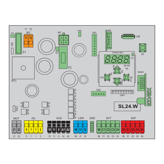
SL24.W 4 - Power supply connection The control panel is powered at the SEC terminal with 24Vac and must be connected to the secondary terminal of a transformer for powering from the mains electricity. The transformer is supplied with the gear motor or control cabinet the control is fitted in and the secondary is pre-wired to the control panel. - Page 6 SL24.W 5.3 - Photocells and photocells in closing with photo-test on 0 1 1 2 99 S1 S2 S3 S4 8K2 (8.2 K ) N.C. 5.4 - Sensitive edge 99 S1 S2 S3 S4 8K2 (8.2 K ) N.C. 99 S1 S2 S3 S4 5.5 - Stop push button...
- Page 7 SL24.W 5.6 - Connecting two control panels in interlocking mode, output A2 = 7 (INB) The interlocking connection involves 2 gates operating according to the following method: - gate 1 opens only if gate 2 is closed - gate 2 opens only if gate 1 is closed When this mode is on, the safety input S4 is automatically configured without the installer selecting it as an interlock input (checking that the other gate is closed).
-
Page 8: Programming The Control Panel
SL24.W 6 - Control panel programming: 6.1 - Preliminary operations To function correctly, the control panel requires some minimum and essential settings. There are two: - Setting the motor type. In its default configuration, the control panel is not associated to any type of motor. The type of motor associated to the control panel must be set. - Page 9 SL24.W Motor parameters Default Type of gear motor used Not set Acto 600D (ESM2) Type of position control Default Automatically set with the choice of gear motor. You are advised not to change the setting given by the type of gear motor.
- Page 10 SL24.W Self-calibration If the gate travel parameter is changed, there is no need for the installer to run new calibrations, however, when chang- ing the travel parameters, the control panel needs to learn the current curve again, thus disabling the obstacle detection only during the self-calibration manoeuvre.
- Page 11 SL24.W Motor stop approach force reduction distance Indicates the distance from the mechanical stop starting from which the motor force is Default reduced by half (used to adjust the impact of the leaf on the mechanical stop). This happens only when the control panel works with encoder and proximity limit switch or without limit switch.
- Page 12 SL24.W Auxiliary output configuration Default Terminal A1 output type OFF Output off Gate open warning light (SCA) Operation as per SCA parameter setting Auxiliary Radio output (RAU) Operation as per RAU parameter setting Courtesy light (LCO) On during leaf movement and for the amount of time after the leaf stopping set in parameter...
- Page 13 SL24.W Default Courtesy light timer 1 s (minimum time) 300 s (maximum time) Default SCA output operating mode Gate closed: off Gate open: on fixed Gate closed: off Gate moving: intermittent Gate open: on fixed Indeterminate position: intermittent pause of 1 s every 5...
- Page 14 SL24.W S1/S2/S3/S4 safety input OFF Off Default S3/S4 Photocell closing (PHC) The closing photocell: - with the gate stopped, allows the gate to open - in opening does not intervene Default S1 - with the gate open, does not allow it to close and when released will reset the...
- Page 15 SL24.W Control panel logic settings Default Automatic closing Automatic closing off Automatic closing on Default Pause time 1 s (minimum time) 180 s (maximum time) Default Pedestrian pause time 1 s (minimum time) 180 s (maximum time) Default State on power up Gate in closed position: The first step-step command opens the gate.
- Page 16 SL24.W Pre-flash Default Flashing time of the flashing light before the gate starts to move Pre-flash disabled 3 s pre-flash 4 s pre-flash 5 s pre-flash Default Manned Manned function off Step-step command disabled, remote controls not working. The control panel accepts only open and close commands Emergency manned.
- Page 17 SL24.W Remote control management Saving a button as step-step oooo Waiting for code 1001 Remote control 1 saved as step-step 1055 Remote control 55 saved as step-step Saving a button as open oooo Waiting for code OPEN 2001 Remote control 1 saved as open...
- Page 18 Press OK for 5 s to enter the number edit mode. Use buttons ▲▼ to change the value, OK to confirm the number, use ESC to return to the previous digit, underscore “_” indicates a space Control panel info display SL24.W Control panel name 1.13 Control panel firmware version...
- Page 19 SL24.W Connection module Default Connection module on CNX1 connector CNX1 No module connected Wi-Fi module EMC.W connected Default Connection module on CNX2 connector CNX2 No module connected Opposing leaf module EMC.DU connected. Control panel functioning as MASTER Opposing leaf module EMC.DU connected. Control panel functioning as SLAVE...
-
Page 20: Diagnostics
SL24.W 7 - Diagnostics: 7.1 - Signalling Signalling indications are shown on the display for events of interest to the installer concerning normal and anomalous operation. They appear on the display when the associated event occurs. These indications may signal a failure if some of the system components are not working (e.g. -
Page 21: Updating Firmware
SL24.W 8 - Updating Firmware: The control panel is equipped with a USB port that is used to update the control panel Firmware or the Wi-Fi EMC.W communication module Firmware Caution: If the firmware updating procedure is not carried out properly it may damage the control panel or the Wi-Fi communica- tion module, make sure not to interrupt the mains power supply during the update. -
Page 22: Control Panel Connection From Smartphone/Tablet
Requirements for establishing the connection - an SL24.W or SW24.W control panel - an EMC.W Wi-Fi connection module - an Android device with at least version 4.4 or iOS minimum version 8.0 with the Wi-Gate app installed (download-... - Page 23 SL24.W EC DECLARATION OF CONFORMITY (Declaration of incorporation of partly completed machinery annex IIB 2006/42/EC No.: ZDT00744.00 The undersigned, representing the following manufacturer Vimar SpA Viale Vicenza 14, 36063 Marostica VI Italy declares under his own responsibility that the products...
- Page 24 Viale Vicenza 14 36063 Marostica VI - Italy www.vimar.com SL24.W installer EN 02 1708...
Need help?
Do you have a question about the SL24.W and is the answer not in the manual?
Questions and answers