
Related Manuals for MTS Systems 111 Series


Summary of Contents for MTS Systems 111 Series
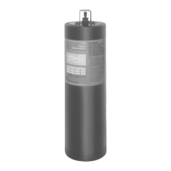
- Page 1 Series 111 Accumulator Product Information Model 111.11 Model 111.12 011-553-304 B...
- Page 2 Copyright information © 2000 MTS Systems Corporation. All rights reserved. Trademark information MTS is a registered trademark of MTS Systems Corporation. Contact information MTS Systems Corporation 14000 Technology Drive Eden Prairie, Minnesota 55344-2290 USA Toll Free Phone: 800-328-2255 (within the U.S. or Canada) Phone: 612-937-4000 (outside the U.S.
-
Page 3: Table Of Contents
Contents Introduction 5 Functional Description Specifications Installation 9 Maintenance 11 Checking the Accumulator Precharge Changing the Precharge Pressure Purging Fluid from the Gas Chamber Removing the Accumulator Replacing the Accumulator Seal Series 111 Accumulators Contents... - Page 4 Series 111 Accumulators...
-
Page 5: Introduction
Contents Functional Description Specifications What you need to MTS Systems Corporation assumes that you know how to use your know controller. See the appropriate manual for information about performing any controller-related step in this manual’s procedures. You are expected to know how to perform the following procedures: •... -
Page 6: Functional Description
Functional Description The MTS Series 111 Accumulators can reduce fluctuations hydraulic lines due to sudden changes in hydraulic flow rate. They also act a short term energy source for high-rate tests by providing additional hydraulic flow for short periods to meet irregular peak demands. Like a capacitor, accumulators filter out pulses in the hydraulic fluid to provide steady hydraulic pressure. -
Page 7: Specifications
* The models listed in this table are considered standard models. Other models may be manufactured with different capacities, lengths, or hydraulic fluid port connections than listed here. Contact MTS Systems Corporation for information on nonstandard models. † See the figures on the next page. - Page 8 The cross-section figures shown on this page illustrate the difference between the accumulator models. Typical Boss Adapter Fitting Ref. 1.563 in. (39.7 mm) Length Relief Vent Hydraulic Accumulator Fluid Port Locking Pin Valve Assembly Protective Cover Model 111.11B Accumulator Cross-section Ref.
-
Page 9: Installation
Installation There are two models of the Series 111 Accumulator. The following figure shows the typical mounting configuration for the Models 111.11B and 111.12C Accumulators. • The Model 111.11B Accumulator is mounted with a boss adapter fitting and O-ring seals. When the accumulator is ordered as a component, the boss adapter and O-ring seals are not included with the accumulator, they must be purchased separately. - Page 10 Note When installing a replacement accumulator into an existing system, the replacement accumulator should be precharged to the same pressure level as the accumulator being removed. Be sure that this precharge level is recorded on the label of the replacement accumulator. Procedure Complete the following steps to mount the accumulator.
-
Page 11: Maintenance
Maintenance This section describes how to maintain the charge in the accumulator. Contents Checking the Accumulator Precharge Changing the Precharge Pressure Purging Fluid from the Gas Chamber Removing the Accumulator Replacing the Accumulator Seal Maintenance Maintaining the proper pressure level for your accumulators is essential for guidelines optimum system performance and component life. - Page 12 • Because the precharge pressure level varies with a temperature change, the level should always be checked at the same temperature. If it is not, use one of the following formulas to determine if the precharge level is acceptable. Degrees Fahrenheit: ...
-
Page 13: Checking The Accumulator Precharge
Checking the Accumulator Precharge Special equipment The following equipment is for any Series 111 Accumulator: • Accumulator charging kit (MTS part number 376986-01) Procedure To check your accumulator precharge, perform the following: WARNING Accumulators are pressurized devices. Pressurized accumulators and their parts can become lethal projectiles if disassembled and can cause death to persons and/or damage to equipment. - Page 14 Checking the Series 111 Accumulator Precharge The Series 111 Accumulators use the poppet-type valve (as shown on the previous page). 1. Connect the charging kit chuck valve to the accumulator valve stem. 2. With an open-end wrench, turn the locknut counterclockwise on the accumulator valve assembly to open the valve.
-
Page 15: Changing The Precharge Pressure
Changing the Precharge Pressure Often the precharge of an accumulator mounted on a hydraulic supply line is increased to enhance system performance and reduce the transient HPS flow demands. Accumulators may be precharged to 10 MPa (1500 psi) or more, although amounts above 14 MPa (2200 psi) will have less and less performance effect in most situations. - Page 16 4. Open the nitrogen bottle valve. Check the nitrogen bottle pressure gage on the regulator. (The bottle must contain sufficient pressure to provide an adequate gas volume.) 5. Monitor the regulator output pressure gage and adjust the regulator output pressure valve to the required level. CAUTION Avoid rapid and extreme pressure transitions.
-
Page 17: Purging Fluid From The Gas Chamber
Purging Fluid from the Gas Chamber When you should Piston-type accumulators may collect hydraulic fluid in the gas chamber, perform this which then reduces the gas volume of the accumulator. The fluid should procedure be purged from the gas side if a pressure check procedure shows one or more of the following: •... -
Page 18: Removing The Accumulator
Removing the Accumulator Perform the following steps to remove the accumulator. WARNING Accumulators are pressurized devices. Pressurized accumulators and their parts can become lethal projectiles if disassembled and can cause death to persons and/or damage to equipment. Do not remove an accumulator that is pressurized. Completely remove hydraulic pressure and discharge the accumulator before any parts, except the protective cover and valve stem cap are removed. -
Page 19: Replacing The Accumulator Seal
Replacing the Accumulator Seal Special equipment The following equipment is required to replace any Series 111 Accumulator seals: • A seal kit (MTS part number 041-463-501 for the Model 111.11B or MTS part number 041-463-301 for the Model 111.12C) • Accumulator charging kit (MTS part number 376986-01) Procedure Use the following procedure to replace any Series 111 Accumulator seals:... - Page 20 6. See “Accumulator Seal Details” on page 19 for details A and B for this step. Remove the end cap backup ring and seal (detail A), and the piston seals and wear strip (detail B). Clean the cylinder with a soft cloth and inspect the piston and inner walls for scratches.
Need help?
Do you have a question about the 111 Series and is the answer not in the manual?
Questions and answers