Table of Contents
Advertisement
1200/2200
Sound Level Meters
Operator's Manual
Note: Due to the new ATEX Directive in Europe, all references in this
document to "Ex" or "EEx" for intrinsic safety approvals should be disregarded
effective 7/1/03 within the member countries of the European Union (EU). At
this time, this product is not approved in accordance with the new ATEX
Directive and is not sold for use in hazardous atmospheres or explosive zones by
customers within the EU. Outside of the EU, all references to intrinsic safety
continue without change.
Thank you for choosing Quest Technologies to meet your sound measuring
needs. The Quest 1200 Sound Level Meter is a light weight easy-to-use Type 1
instrument and the 2200 is our Type 2 model. It is our goal to make your deci-
sion to buy Quest products the right one, and to provide support for any ques-
tions or concerns that might arise.
The purpose of this manual is to provide the user with the necessary information
to operate the 1200/2200 Sound Level Meter as well as the remoteable versions
of the 1200R/2200R. The entire manual should be read to fully understand the
many features this instrument offers.
This manual is not all inclusive and cannot cover all unique situations. In addi-
tion, no warranties are contained in this manual except as described under the
warranty policy section.
Copyright 2000
Revision A
P/N 056-653
1060 Corporate Center Drive • Oconomowoc, WI 53066 USA • 800-245-0779 • Fax: 262-567-4047
http://quest-technologies.com
Printed in U.S.A
Advertisement
Table of Contents

Subscribe to Our Youtube Channel
Related Manuals for Quest Technologies 2200


Summary of Contents for Quest Technologies 2200
- Page 1 The Quest 1200 Sound Level Meter is a light weight easy-to-use Type 1 instrument and the 2200 is our Type 2 model. It is our goal to make your deci- sion to buy Quest products the right one, and to provide support for any ques- tions or concerns that might arise.
-
Page 2: Table Of Contents
2.2.3 FAST/SLOW/PEAK/IMP RESPONSE Switch ....4 2.2.4 A/C/Z Switch ..............4 The models 1200 and 2200 are easy-to-use hand held meters with an LCD 2.2.5 RANGE (dB) Switch............4 display that provides a numerical readout. They are housed in an R.F. -
Page 3: General Overview
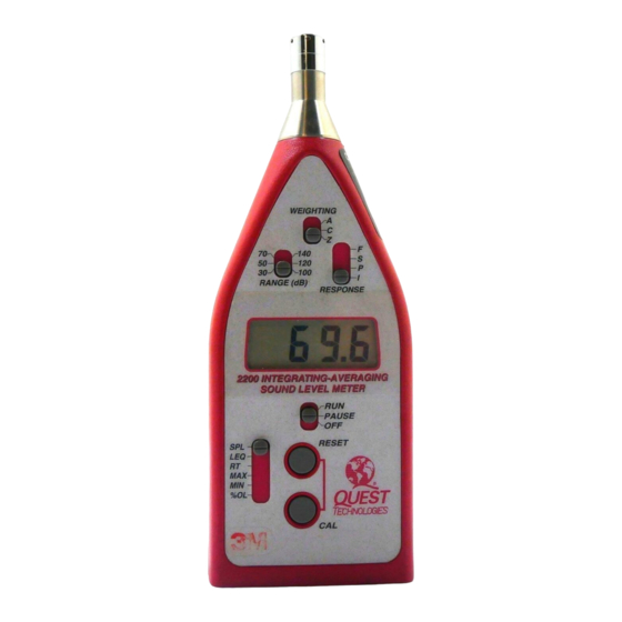
2. GENERAL OVERVIEW 2.1 The Display: The LCD display provides a numeric readout in 0.1 dB increments along with a LOBAT (low battery) indicator. The LOBAT indicator will turn on when the voltage of the battery is too low to allow an accurate reading. A plus sign '+' will appear on the left side of the display if signal peaks cause an overload condition in the electronics. -
Page 4: Fast/Slow/Peak/Imp Response Switch
• RT - In the RT mode the display shows the elapsed time of the current or 2.2.4 A/C/Z Switch: last RUN. The RT mode consists of two or three displays. The first is RUN The A/C/Z switch controls the frequency response (weighting) of all TIME seconds ':XX'. -
Page 5: Output Jack
2.3 Output Jack: 3. METER INTEGRITY The model 1200 provides an output jack on the bottom of the meter for measuring the weighted AC signal before the rms/log detector and the DC 3.1 Power On and Battery Check: output of that detector. Both signals are real time, i.e. LEQ is not Set the OFF/PAUSE/RUN switch to either the PAUSE or RUN position as represented at the DC output. -
Page 6: Changing The Calibration Level
At this point, pressing either the CAL or RESET button will toggle the Turn to calibrator ON. If optional, set the frequency to 1 KHz. Exchange Rate between 'Er3' and 'Er5'. Place the black adapter ring fully onto the microphone. When the desired Exchange Rate is displayed, store the selection by pressing both the CAL and RESET buttons simultaneously. -
Page 7: Operation
Avoid placement against a wall or in a corner. A threaded bushing on the back will accept a standard 1/4-20 tripod fitting. The microphone cartridge used on the models 1200 and 2200 is a free-field microphone. Point it directly at the noise source (0 degrees ). -
Page 8: Windscreen Effects
For example, if the background noise is 45dB and the sound of interest 4.4 Data Recording: measures 51dB, the difference between measurement and background The model 1200 has a DC output that is linearly related to the decibel noise is 6dB. From Figure 3, for a 6dB difference, 1.3dB should be reading on the LCD display by 16.7mV/dB (1V/60dB). -
Page 9: Technical Information
A typical response curve for the Type 2 microphone is shown in Figure 6. The model 2200 is designed to accept a prepolarized (electret) Type 2 microphone Quest P/N #056-316 (QE7052). The impedance of this micro- phone is approximately 15pF. The microphone screws directly onto either the remoteable preamp or the fixed microphone extension of the meter case. -
Page 10: Weighting Characteristics
5.3 Microphone Preamplifier Extension Cables 5.5 Weighting Characteristics On 1200R (Remote) units the preamplifier is removable by unscrewing the The weighting characteristics (frequency response) for A, C, and Z are black plastic collar below the preamplifier housing. The 1200 will drive up shown in Figure 10. -
Page 11: Specifications
6. SPECIFICATIONS Standards: Model 1200 : Type 1 ; Model 2200 : Type 2 ANSI Sl.43-1997, ANSI sl.4-1983(R1997), IEC 651-1979, IEC 804-1985 Display: 3 1/2 Digit Liquid Crystal Display. Level display indicates to 0.1 dB resolution. An enunciator is included for Battery Check. - Page 12 Time: Signal Dependent - approximately 2.5 hours at a Size: 2200: 2.8 x 7.6 x 1.3 inches (including mic) constant 140dB SPL. Time will double with each 3dB 1200: 2.8 x 9.7 x 1.3 inches (including mic) decrease in average SPL, until limited by battery life.
-
Page 13: Accessories
If for any reason you should find it necessary to contact the factory regard- ing service or shipping damage, please direct your calls or letters to the attention of the Service Manager, Quest Technologies, (262) 567-9157 or (800) 245- 0779. Office hours are from 7 AM to 6 PM (Central Standard Time) Monday through Friday. -
Page 14: Quest Warranty Policy
QUEST WARRANTY POLICY Warranty Policy Quest Technologies warrants our instruments to be free from defects in materials and workmanship for one year under normal conditions of use and service. For U.S.A. customers we will replace or repair (our option) defective...
Need help?
Do you have a question about the 2200 and is the answer not in the manual?
Questions and answers