Advertisement
Quick Links
Congratulations on the installation of the GOST Phantom wireless vessel security and monitoring system. The product is designed to
wirelessly communicate with the assorted security and monitoring zones aboard the vessel. This provides reliable protection while alerting
contacts of events via voice message and/or text messages, giving the owner true piece of mind. This guide is provided to bring the installer
through the basic installation, setup, and wireless programming of the GOST Phantom. It is recommended that the installer read this entire
guide fully before beginning. It is important that the installer has an understanding of marine electrical fundamentals and adheres to the NMEA
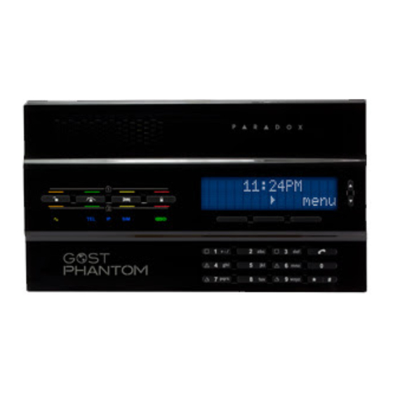
standards of marine electronics. Figure 1 below identifies the keypad functions and LEDs on the front of the panel.
The GOST Phantom allows programming for:
64 Wireless zones from security to utility monitoring throughout vessel
8 wireless relays to control virtually any AC/DC switch, deck lights, sirens, strobes, ice makers, etc.
4 wireless keypads for additional arming control from staterooms, entry points, crew quarters, etc.
4 repeaters to double the wireless range commonly used on metal boats and vessels greater that 125 ft.
4 Siren/Strobes for simple implementation in various points around exterior of vessel
2 doorbell zones for notification at boarding entry points where individuals come aboard the vessel.
2 Independent partitions to arm/ disarm different areas of vessel such as Living Quarters and Crew/Utility Areas.
Location Considerations
The placement of the GOST Phantom aboard the vessel should be well thought out and reviewed with the yacht owner/crew prior to
installation. The installer must make sure that adequate security concerns, end user ease of use, and functionality of speakerphone are taken
into account. Reference the following guidelines before drilling any holes or running any wires.
Interior of boat, away from any direct moisture
Common areas such as the salon, interior helm, or similar primary entry areas of the vessel.
Easy accessibility for someone boarding the boat
On larger vessels greater than 100ft (Approx. 30 meters) try to keep the head unit towards midship to maximize wireless range
Accommodate for wire run accessibility from rear of panel to power source and GSM/Satellite phone*.
*When connecting to third party satellite phone communicator.
Mounting
The GOST Phantom head unit conveniently pivots and detaches off its upper hinges for ease of installation. To access the mounting base
plate, unscrew the cover lock down screws from the bottom side as so they are free hanging. Now gingerly fold the bottom apart from the top
hinge (Figure 2 right). Assure that you unplug or plug in the battery cable to the rear of the board when removing or securing the cover
(respectively).
Screw in the mounting plate at any of the mounting holes in Figure 2 at the orange dots. The mounting plate also has "Mounting
Security" option that can be used to alarm the GOST Phantom if it is opened or torn off the wall (Figure 2).
Figure 1
support@gostglobal.com
GOST Phantom – Installation + Programming Guide
or (954) 565-9898
1
Advertisement

Related Manuals for Gost Phantom


Summary of Contents for Gost Phantom
- Page 1 Location Considerations The placement of the GOST Phantom aboard the vessel should be well thought out and reviewed with the yacht owner/crew prior to installation. The installer must make sure that adequate security concerns, end user ease of use, and functionality of speakerphone are taken into account.
-
Page 2: Power Supply
Power Supply The GOST Phantom needs a 7.5 Volt Direct Current (VDC) to operate (Figure 2). The unit includes a 110 - 240 VAC to 7.5 VDC transformer (PA-7). The GOST Phantom will call up to eight recipients in the event of panel AC Power loss (after default 15 minutes) and then restoration. - Page 3 “Tip” and “Ring” (no SMS Messaging). In either case, you will most likely have a four conductor RJ-11 telephone cable coming from the communication method. After the cable is run to the GOST Phantom, take the two center Red and Green wires to the Ring + Tip (respectively) as displayed in Figure 2 on the previous page.
- Page 4 (Figure 4). The GOST Phantom protects both the client and installer on different levels. When entering the master code at “08-System Setup” one menu appears, when entering the Installer code a different menu appears (review menu flow charts in Figure 5 and Figure 6, respectively).
- Page 5 GOST Phantom – Installation + Programming Guide Figure 5 support@gostglobal.com or (954) 565-9898...
- Page 6 GOST Phantom – Installation + Programming Guide Figure 6 support@gostglobal.com or (954) 565-9898...
- Page 7 When using the onboard GSM module for the GOST Phantom, the use of text messaging to transmit GOST Phantom conditions is a valuable tool. As you proceed thru the various menu items for adding users, zones, relays, areas, etc., you will have the option to enter text labels. See the example in Figure 8 that describes how to enter labels a zone the process is the same for entering any text label.
-
Page 8: System Setup
You can program up to sixteen different users onto the GOST Phantom. A User is defined as a person with access to the system via a pass code and/or key fob remote. - Page 9 The GOST Phantom system can hold up to 64 of these zones. It is important to understand the standard programming steps to setup each sensor as a zone on the GOST Phantom. Each...
- Page 10 GOST Phantom – Installation + Programming Guide You are now prompted to select a zone “type”. This is the action that you want the zone to take when it opens and closes accordingly. There are many different definitions of zone types.
- Page 11 80 second Delay on breach before alarm (24/7) Assigning Zones to Areas An “Area” of the GOST Phantom can also be described as a partition. The GOST Phantom has two partitions. This feature allows two independent areas of the boat to be armed and disarmed.
- Page 12 GOST Phantom. The hardwired Outputs on system is stay armed. Common examples of triggered devices the back of the GOST Phantom can trigger an external 12V may be interior lamps that come on inside the salon. relay if wireless connection is not needed. The system can...
- Page 13 GOST Phantom – Installation + Programming Guide support@gostglobal.com or (954) 565-9898...
- Page 14 (Figure 12). It comes in handy if client wants to keep the GOST Phantom covert. It also provides additional control stations for Staterooms, crew quarters, and secondary entry areas.
- Page 15 GOST Phantom – Installation + Programming Guide The Repeater (GMM-IP65-RP) is used to double “05-Repeaters” the wireless range of the GOST Phantom’s assorted zones, outputs, or wireless keypads. It is used on vessels usually 80+ Feet where diamond plating, metallic sound proofing, or multiple bulkheads reduce wireless range.
- Page 16 GOST Phantom – Installation + Programming Guide The GOST Phantom has the ability to work with “06-Sirens” a wireless siren/ strobe (GMM-SRN-STR). This device is extremely useful where an easily implemented sound and flashing light could be used to deter theft. Common locations are under gunwales aboard the boat or mounted to pilings on the dock next to the boat.
- Page 17 GOST Phantom – Installation + Programming Guide Some clients on larger boats with boarding stairs “07-Doorbells” like to have a wireless door bell to alert the GOST Phantom System and their crew that someone is waiting to board the vessel. It is suggested that a...
- Page 18 GOST Phantom – Installation + Programming Guide “08-Delays / Tones” support@gostglobal.com or (954) 565-9898...
- Page 19 GOST Phantom – Installation + Programming Guide The GOST Phantom has a built in speakerphone. This feature “09-Communicator” can be used with the onboard GSM module or thru the Ring and tip (RJ-11) for external GSM module or Satellite phone. In...
- Page 20 GOST Phantom – Installation + Programming Guide support@gostglobal.com or (954) 565-9898...
-
Page 21: System Test
GOST Phantom – Installation + Programming Guide “10-Installer ID” It is not necessary to modify this area of programming unless directed by the owner of if the installer has security concerns of someone changing installer codes on the system. Consult GOST support if further information is needed on this section. - Page 22 GOST Phantom – Installation + Programming Guide Trouble Display When the GOST Phantom wants you to know something is wrong, an “i” will appear on the screen along with an audible beep. After viewing the trouble by pressing the left menu action key, you view the trouble, and press “ok”...
-
Page 23: Frequently Asked Questions (Faqs)
FAQ 4: The GOST Phantom is powered off of the AC to DC transformer that is included with the system. The Voice reporting is configured to report trouble for AC power Loss/Restoration, thus when the Boat looses shore power a call will be placed.
Need help?
Do you have a question about the Phantom and is the answer not in the manual?
Questions and answers