Table of Contents
Advertisement
Quick Links
P/N:4710.0015
Release Date: June. 2014
Contents
1
1.1
Safety Overview . . . . . . . . . . . . . . . . . . . . . . . . . . . . . . 1-1
1.2
Description of Symbols and Signal Words Used . . . . . . . . . . . . . . 1-2
1.2.1
Symbols . . . . . . . . . . . . . . . . . . . . . . . . . . . . . . 1-2
1.2.2
Signal words . . . . . . . . . . . . . . . . . . . . . . . . . . . . 1-3
1.3
Messages . . . . . . . . . . . . . . . . . . . . . . . . . . . . . . . . . 1-4
1.4
1.5
Biological Safety . . . . . . . . . . . . . . . . . . . . . . . . . . . . . . 1-4
1.6
Scanning Patients and Education . . . . . . . . . . . . . . . . . . . . . 1-5
1.6.1
Safe Scanning Guideline . . . . . . . . . . . . . . . . . . . . . 1-5
1.6.2
Understanding the MI/TI Display . . . . . . . . . . . . . . . . . 1-7
1.7
Environmental Requirements . . . . . . . . . . . . . . . . . . . . . . . 1-10
1.8
Electrical Requirements . . . . . . . . . . . . . . . . . . . . . . . . . . 1-10
1.9
Electrical Safety . . . . . . . . . . . . . . . . . . . . . . . . . . . . . . 1-12
1.10
Cautions for Using Accessories . . . . . . . . . . . . . . . . . . . . . . 1-13
1.10.1
Foot Switch . . . . . . . . . . . . . . . . . . . . . . . . . . . . 1-13
1.10.2
Optional Printers . . . . . . . . . . . . . . . . . . . . . . . . . . 1-13
1.10.3
Transducer Maintenance . . . . . . . . . . . . . . . . . . . . . 1-13
1.11
Environmental Protection . . . . . . . . . . . . . . . . . . . . . . . . . 1-16
1.12
System Transportation . . . . . . . . . . . . . . . . . . . . . . . . . . . 1-17
1.12.1
Moving the System . . . . . . . . . . . . . . . . . . . . . . . . 1-17
1.12.2
Transporting the System . . . . . . . . . . . . . . . . . . . . . . 1-17
2
2.1
Application and Contraindication . . . . . . . . . . . . . . . . . . . . . . 2-2
2.2
Base System . . . . . . . . . . . . . . . . . . . . . . . . . . . . . . . . 2-2
2.3
Probes and Accessories . . . . . . . . . . . . . . . . . . . . . . . . . . 2-4
2.4
Physical Specifications . . . . . . . . . . . . . . . . . . . . . . . . . . . 2-5
2.5
Concept of Operation . . . . . . . . . . . . . . . . . . . . . . . . . . . 2-5
2.5.1
Screen Layout . . . . . . . . . . . . . . . . . . . . . . . . . . . 2-5
2.5.2
Keyboard Layout . . . . . . . . . . . . . . . . . . . . . . . . . . 2-6
2.5.3
Keyboard Description . . . . . . . . . . . . . . . . . . . . . . . 2-7
2.5.4
General Operation Instructions . . . . . . . . . . . . . . . . . . 2-11
3
3.1
Probe Connection . . . . . . . . . . . . . . . . . . . . . . . . . . . . . 3-1
3.2
Power On and Off . . . . . . . . . . . . . . . . . . . . . . . . . . . . . 3-2
3.2.1
3.2.2
Using Battery . . . . . . . . . . . . . . . . . . . . . . . . . . . 3-3
3.2.3
LED Indicators . . . . . . . . . . . . . . . . . . . . . . . . . . . 3-4
3.3
Patient Information . . . . . . . . . . . . . . . . . . . . . . . . . . . . . 3-5
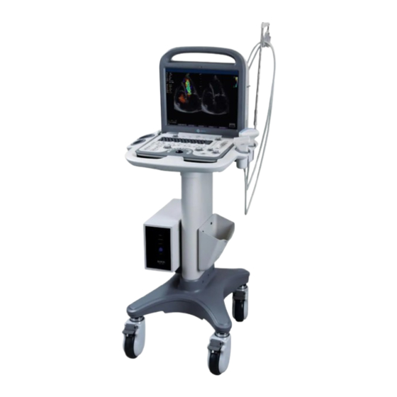
Portable Digital Color Doppler Ultrasound System
. . . . . . . . . . . . . . . . . . . . . 1-4
. . . . . . . . . . . . . . . . . . . . . . . . . 3-2
i
P11
1-1
2-1
3-1
Advertisement
Table of Contents

Related Manuals for MediSono P11


Summary of Contents for MediSono P11
-
Page 1: Table Of Contents
Portable Digital Color Doppler Ultrasound System P/N:4710.0015 Release Date: June. 2014 Contents System Safety and Maintenance Safety Overview ......1-1 Description of Symbols and Signal Words Used . - Page 2 Portable Digital Color Doppler Ultrasound System Start Ultrasound Diagnosis ......3-6 3.4.1 Customized application mode (Create New Exam Mode) ..3-7 3.4.2 Annotation and Bodymark .
- Page 3 Portable Digital Color Doppler Ultrasound System 5.4.5 Select Image Sequence ..... . 5-11 5.4.6 Cine Playback ......5-11 5.4.7 Saving Image/Cine .
- Page 4 Portable Digital Color Doppler Ultrasound System 7.4.1 Color Map ......7-6 7.4.2 B Reject .
- Page 5 Portable Digital Color Doppler Ultrasound System 10.2.3 Pulse Repetition Frequency (PRF) ....10-5 10.2.4 Wall Filter (WF) ......10-5 10.2.5 Spectral Doppler Gain .
- Page 6 Portable Digital Color Doppler Ultrasound System 12.3.1 Adjustment of Sample Box & Cut Off Line ... . . 12-2 12.3.2 Cine Review ......12-3 12.3.3 Sweep Angle .
-
Page 7: System Safety And Maintenance
Chapter 1 System Safety and Maintenance 1.1 Safety Overview This section discusses measures to ensure the safety of both the operator and patient. To ensure the safety of both operator and patient, please read the relevant details in this chapter carefully before operating this system. Disregarding the WARNINGS or violation of relevant rules may result in personal injury or even loss of life for operator or patient. -
Page 8: Description Of Symbols And Signal Words Used
Portable Digital Color Doppler Ultrasound System • Do not use this system in the presence of flammable substances or an explosion may occur. • Do not continuously scan the same part of a patient or expose the patient to prolonged scanning. -
Page 9: Signal Words
Portable Digital Color Doppler Ultrasound System Manufacturer information according to EN 980. Date of manufacture according to EN 980. Consult operating instructions. Network Port. Control port of color video printer. USB Port Video input Video Output Fragile. Keep dry. Maximum stacking limit of packages. Maximum of two layers allowed! Keep this way upward. -
Page 10: Messages
Portable Digital Color Doppler Ultrasound System 1.3 Messages All the messages generated by this ultrasound system are self-explanatory. However, you may encounter the following situations. License renewal When the validity of the license is less than 10 days, the message on the above right will appear on the preparation mode (EXAM) screen. -
Page 11: Scanning Patients And Education
Portable Digital Color Doppler Ultrasound System There are no confirmed biological effects on patients or instrument oper- ators caused by exposures from present diagnostic ultrasound instruments. Although the possibility exists that such biological effects may be identified in the future, current data indicate that the benefits to patients of the prudent use of diagnostic ultrasound outweigh the risks, if any that may be present. - Page 12 Portable Digital Color Doppler Ultrasound System 3. Operators should understand the likely influence of the machine controls, the op- erating mode (e.g. B-mode, color Doppler imaging or spectral Doppler) and probe frequency on thermal and cavitation hazards. 4. Select a low setting for each new patient. Output should only be increased during the examination if penetration is still required to achieve a satisfactory result, and after the Gain control has been moved to its maximum value.
-
Page 13: Understanding The Mi/Ti Display
Portable Digital Color Doppler Ultrasound System 11. Non-diagnostic use of ultrasound equipment is not generally recommended. Ex- amples of non-diagnostic uses of ultrasound equipment include repeated scans for operator training, equipment demonstration using normal subjects, and the production of souvenir pictures or videos of a fetus. For equipment of which the safety indices are displayed over their full range of values, the TI should always be less than 0.5 and the MI should always be less than 0.3. - Page 14 Portable Digital Color Doppler Ultrasound System is for ophthalmic use, in which case the TI=max (TIS_as, TIC) is not to exceed 1.0; Ispta.3 50mW/cm2, and MI 0.23. Track-3 gives the user the freedom to increase the output acoustic power for a specific exam, and still limit output acoustic power within the global maximum de-rated Ispta 720 mW/cm2 under an Output Display Standard.
- Page 15 Portable Digital Color Doppler Ultrasound System Tissue temperature elevation depends on power, tissue type, beam width, and scanning mode. Six models are developed to mimic possible clinical situations. Thermal Composition Mode Specification Typ. app Models 1TIS Soft tissue Unscanned Large aperture Liver PW (>1cm ) 2TIS...
-
Page 16: Environmental Requirements
Portable Digital Color Doppler Ultrasound System Display Guideline For different operation modes, different indices must be displayed. However, only one index needs to be shown at a time. Display is not required if maximum MI is less than 1.0 for any setting of the operating mode, or if maximum TI is less than 1.0 for any setting of the operating mode. - Page 17 Caution for using AC adapter: • Use the AC adapter approved by MediSono only. • AC adapter can get very hot if being used in poorly ventilated area. Main- tain good ventilation for heat dissipation. Do not put any items on the AC adapter or the power cable.
-
Page 18: Electrical Safety
Portable Digital Color Doppler Ultrasound System 1.9 Electrical Safety Caution! Only trained health-care professionals should operate this system. This equipment complies with the following standards: • The equipment conforms with the following regulations for electrical safety, – EN 60601-1 (IEC 60601-1), Medical electrical equipment Part 1: General requirements for basic safety and essential performance, Class I, BF, continuous operation. -
Page 19: Cautions For Using Accessories
Portable Digital Color Doppler Ultrasound System 1.10 Cautions for Using Accessories • Any accessories, provided by other manufacturers other than MediSono, to be connected either electrically or mechanically to this ultrasound system must comply with the specified IEC standards (IEC 60950 Information Technology Equipment - Safety and IEC 60601-1 Medical electrical equipment Part 1: General requirements for basic safety and essential performance.) - Page 20 Portable Digital Color Doppler Ultrasound System Guidelines for Cleaning and Preparing Endocavitary Ultrasound Transducers between Patients from AIUM Approved June 4, 2003 The purpose of this document is to provide guidance regarding the clean- ing and disinfection of transvaginal and transrectal ultrasound probes. All sterilization/disinfection represents a statistical reduction in the number of microbes present on a surface.
- Page 21 3) You should consult the manufacturer’s instructions to prepare, store and use the disin- fectant. Consult MediSono if you are not sure about the compatibility of these agents with the probes. Many of the chemical disinfectants are potentially toxic and many require adequate precautions, such as proper ventilation, personal protective devices (gloves, face/eye protection, etc.) and rinsing before reusing the probe.
-
Page 22: Environmental Protection
Portable Digital Color Doppler Ultrasound System 2. Gloves should be used to remove the condom or other barrier from the transducer and to wash the transducer as mentioned above. 3. As the probe sheath is removed, care should be taken not to contaminate the probe with secretions from the patient. -
Page 23: System Transportation
Portable Digital Color Doppler Ultrasound System Disposal of System Contact MediSono or our representatives nearest to you for proper disposal instructions. Disposal of Accessories Contact the manufacturers of these products for proper disposal instructions. Disposal of Waste Products and Residues Ultrasound coupling gel is water-solvable;... - Page 24 Portable Digital Color Doppler Ultrasound System 1-18...
-
Page 25: System Specifications
Portable Digital Color Doppler Ultrasound System Chapter 2 System Specifications Contents Application and Contraindication ..... . . 2-2 Base System ....... . . 2-2 Probes and Accessories . -
Page 26: Application And Contraindication
Portable Digital Color Doppler Ultrasound System 2.1 Application and Contraindication Application: 1. Fetal 2. Abdominal 3. Pediatric 4. Small parts (breast, testes, thyroid) 5. Cephalic (neonatal and adult) 6. Trans-rectal 7. Trans-vaginal 8. Trans-esoph. (cardiac) 9. Peripheral vascular 10. Musculo-skeletal (conventional and superficial) 11. - Page 27 Portable Digital Color Doppler Ultrasound System Side View Figure 2.1: Side view Audio Out S-Video Port Two USB Ports Ethernet Port VGA Port Information for using S-Video and composite video Figure 2.1 • This system supports both S-Video (2 in ) and composite Figure 2.2 video (5 in...
-
Page 28: Probes And Accessories
Portable Digital Color Doppler Ultrasound System Rear View Figure 2.2: Rear view Probe Connection Port 1 ECG Port Probe Connection Port 2 Equipotential point (earth) Video Printer Controller Port DC input Foot Switch Socket Composite Video Out 2.3 Probes and Accessories Supported Transducers: see Table 13.1. -
Page 29: Physical Specifications
Portable Digital Color Doppler Ultrasound System 2.4 Physical Specifications Weight (system alone, without docking cart): approximately 13.5kg Dimensions (with lid closed L W H): 400mm 350mm 230mm 2.5 Concept of Operation 2.5.1 Screen Layout The user interface of the preparation mode is shown in Figure 2.3. New Hosp. -
Page 30: Keyboard Layout
Portable Digital Color Doppler Ultrasound System SG Hospital MI 0.7 TIS 1.0 Barret King Mar-29-2010 16:22:21 012589 cm/s cm/s CINE Directional DPI Figure 2.4: application mode screen Logo Color Image Info Spectral Doppler Image Info, or M Hospital Name Mode Image Info, or Context Menu Patient ID THI and PW/CW status... -
Page 31: Keyboard Description
Portable Digital Color Doppler Ultrasound System Figure 2.5: Keyboard layout of the system 2.5.3 Keyboard Description Description EXAM return the system to the preparation mode (EXAM screen). Patient access the Patient Information interface. Dual activate the dual display format. flip the ultrasound image left/right. flip the ultrasound image upward/downward. - Page 32 Portable Digital Color Doppler Ultrasound System Description of the Usage Finv activate the Flow Invert function. Arrow insert an arrow symbol on the ultrasound image 3D/4D start volume mode (3D or real time 4D mode). m-Tuning press this key during scanning to let the system automatically adjust various parameters to obtain high quality image.
- Page 33 Portable Digital Color Doppler Ultrasound System Description of the Usage activate the Tissue Harmonic Imaging. turn on/off Color Doppler Imaging. turn on/off Doppler Power Imaging. PW/CW turn on/off spectral Doppler imaging. PW mode is activated by default. To switch to CW mode, press C or use the use the item CW in the PW context menu.
- Page 34 Portable Digital Color Doppler Ultrasound System Description of the Usage Trackball use the trackball to move the cursor position. UPDATE in spectral Doppler mode or M mode, press this key to start/stop PW/CW and M traces. in 3D mode press this key to toggle the selection between 2D and 3D images.
-
Page 35: General Operation Instructions
Portable Digital Color Doppler Ultrasound System 2.5.4 General Operation Instructions Typography Convention This manual employs the following typefaces to denote keys, buttons and parameters. Keys on the control panel (keyboard) are typed in the form of KEY . Buttons and items shown on the screen are typed in the form of BUTTON. Image parameters on the screen are typed in the form of parameter Move the Cursor Around... - Page 36 Portable Digital Color Doppler Ultrasound System 2-12...
-
Page 37: Starting The System
Portable Digital Color Doppler Ultrasound System Chapter 3 Starting the System Contents Probe Connection ....... 3-1 Power On and Off . -
Page 38: Power On And Off
With the external AC power supply available, it is always recommended to use the AC supply instead of the battery. Warning! • The AC adapter is specifically designed for the MediSono P11 ultrasound system, do not use it with other equipments. To avoid electric hazard and system damage, use only the AC adapter approved by MediSono with the this ultrasound system. -
Page 39: Using Battery
Portable Digital Color Doppler Ultrasound System Incorrect: Correct: loose connection tight connection Figure 3.1: Connecting the DC output plug Notes: Section • If battery is in use, to switch the power supply to AC, follow 3.2.2 Warning! Do not allow the adaptor to hang in the air. Place it on the ground or other well ventilated platform instead. -
Page 40: Led Indicators
Portable Digital Color Doppler Ultrasound System Turn on the system without connecting the AC adapter to use the battery as the source. Disconnect the output plug of the AC adapter from the system while it is on, and the system uses battery as the source automatically. -
Page 41: Patient Information
Portable Digital Color Doppler Ultrasound System indicators Battery Charge AC adaptor indicator indicator indicator Figure 3.2: LED Indicators Using battery. Indications System off System on, battery power high Green and discharging. System on, battery power medium Yellow and discharging. System on, battery power critically low. -
Page 42: Start Ultrasound Diagnosis
Portable Digital Color Doppler Ultrasound System Figure 3.3: Patient Information Note: • For a newly created patient profile, the file folder for this patient is created in the File Manger. • The ultrasound images and calculation results will be saved to the corresponding patient folder. -
Page 43: Customized Application Mode (Create New Exam Mode)
Portable Digital Color Doppler Ultrasound System 3.4.1 Customized application mode (Create New Exam Mode) For each probe, the system has some predefined application modes for some typical applications. User can change various settings based on a predefined mode, and create a customized application mode. - Page 44 Portable Digital Color Doppler Ultrasound System To insert predefined annotations: 1. turn the GAIN knob to scroll between items, turn the D GAIN knob to turn to the next/previous page of annotation items. 2. highlight the annotation item and press the UPDATE key to select the item. 3.
-
Page 45: System Setup
Portable Digital Color Doppler Ultrasound System Chapter 4 System Setup Contents System Menu ....... . . 4-2 File Manager . -
Page 46: System Menu
Portable Digital Color Doppler Ultrasound System 4.1 System Menu At the preparation mode, press Menu , the menu in Figure 4.1 appears on the screen. Figure 4.1: System menu 4.2 File Manager Move the trackball to select File Manager and press Set , the system opens •... -
Page 47: Burn Data To Cd/Dvd
Portable Digital Color Doppler Ultrasound System Figure 4.3: File manager: patient directory Figure 4.3 illustrates the patient directory. The function of the buttons shown in the file manager are listed in Table 4.1. Title Action upon clicking the button LAST PAGE Returns to the root directory. -
Page 48: Facility Name
Portable Digital Color Doppler Ultrasound System 4. Select CD DVD Device in the file manager window and press Set twice. 5. Click WRITE CD/DVD and the files will be burned to the CD/DVD disc. 4.3 Facility Name The facility/hospital name is displayed at the top left corner of the main screen, next to the product logo. -
Page 49: System Setting
Portable Digital Color Doppler Ultrasound System Figure 4.6: System information Caution! DIAGNO option shown at the System Information interface is for system diagnostics or software change. Only authorized service personals should perform this action. 4.6 System Setting Select System Setting and press Set to open the interface for configuring the system. Click the Exit button to exit the System Setting interface. - Page 50 Portable Digital Color Doppler Ultrasound System continued from previous page . . . Language Set the language of the user interface. Screen Saver Turn on or off the screen saver. Trackball Sensitivity Adjust the sensitivity for tracking the trackball movement. Clip Format Set the file format for saving multiple frames as video clips.
-
Page 51: Set Printer
Portable Digital Color Doppler Ultrasound System continued from previous page . . . Report Format Patient report can be saved in or plain format. TEXT 4.6.2 Set Printer Figure 4.8: Set Printer Printer Driver: Select the printer driver to match the actual printer in use. Video Invert: Invert the RGB-color brightness when printing. -
Page 52: Set Measurement Method
Portable Digital Color Doppler Ultrasound System • Press UPDATE to hide or unhide the selected item in the corresponding imaging mode. • When an item contains submenu, press Menu to open or close the submenu. 4.6.4 Set Measurement Method Figure 4.10: Set measurement method Click the Set Measurement Method tab to configure the measurement related settings. - Page 53 Portable Digital Color Doppler Ultrasound System Item Explanation BSA Setting Sets the BSA calculation formula applicable for people. Western Eastern Measure Method Sets the measurement method to Trace Ellipse Package Set it to and only the items related to the application/exam mode Icon Driven will be displayed in the calculation menu.
- Page 54 Portable Digital Color Doppler Ultrasound System continued from previous page . . . AUA Result By Selects the way (by ) to calculate the AUA (Adjusted Ultrasound Average Last Age) result. 4-10...
-
Page 55: Annotation Edit
Portable Digital Color Doppler Ultrasound System 4.6.5 Annotation Edit Figure 4.11: Annotation edit User can modify the predefined annotation strings. Press the Annotation Edit tab, the available annotations and the possible operations are listed on the right half screen. Instructions: •... -
Page 56: Define Quick Key
Portable Digital Color Doppler Ultrasound System 4.6.6 Define Quick Key The numeric keys on the alphanumeric soft keypad can be assigned as shortcut keys for performing measurements. Figure 4.12: Assign shortcut keys Click the Define Quick Key tab to define the shortcut keys. The D. Key column shows the numeric keys;... -
Page 57: Load Default
Portable Digital Color Doppler Ultrasound System 4.6.7 Load Default Figure 4.13: Back up or load user settings 4.6.7.1 Load and Delete General Setting Note: Load Retrieve The profiles under tabs store only the configurations for General Setting. Click the Load tab and select a setting name. The following prompt message appears, Load new setting? continue (Y/N). - Page 58 Portable Digital Color Doppler Ultrasound System Load Create Retrieve Make sure USB drive in the slot Copy user setting to USB Copy user preset to USB Load USB user setting to system Load USB preset to system Caution! Copy USB to hard drive will replace all user setting in the system including patient database.
-
Page 59: Dicom Setting
Portable Digital Color Doppler Ultrasound System 4.6.8 DICOM Setting This equipment conforms with the Digital Imaging and Communications in Medicine (DI- COM) standard, which is the industrial standard for the communication and management of patient data between the devices in the hospital. Click the DICOM Settings tab to modify network, DICOM and print setting. - Page 60 Portable Digital Color Doppler Ultrasound System 4.6.8.2 DICOM Storage Server General Setting Local Storage Worklist Print Log Set Printer Server Name FirstServer Set Calculation Menu IP Address 192.168.254.104 Set Measurement Method Port 9000 Annotation Edit start server AE Title Define Quick Key Timeout (sec) Load Default Echo...
- Page 61 Portable Digital Color Doppler Ultrasound System 4.6.8.3 DICOM Worklist Server Click the Worklist tab to configure the worklist server profile. General Setting Local Storage Worklist Print Log Set Printer Server Name WkServer Set Calculation Menu IP Address 192.168.254.25 Set Measurement Method Port 1200 Annotation Edit...
- Page 62 Portable Digital Color Doppler Ultrasound System 4.6.8.4 DICOM Print Server Click the Print tab to configure the DICOM print server profile. Click to view settings on other pages. General Setting Local Storage Worklist Print Log Set Printer Server Name PrintServer Set Calculation Menu IP Address 192.168.254.23...
- Page 63 Portable Digital Color Doppler Ultrasound System image. Min. Density Specifies the minimum density level of the film. Max. Density Specifies the maximum density level of the film. Border Specifies the color of the border ( ) which fills the Black White gap between the images.
- Page 64 Portable Digital Color Doppler Ultrasound System 4-20...
-
Page 65: B Mode
Portable Digital Color Doppler Ultrasound System Chapter 5 B Mode B mode imaging is intended to provide information of anatomical structure of soft tissues. Contents Starting B Mode ....... 5-2 B Mode Image Information . -
Page 66: Starting B Mode
Portable Digital Color Doppler Ultrasound System 5.5.1 Dual Display Format ......5-12 5.5.2 Quad Display Format ......5-13 Tissue Harmonic Imaging (THI) . -
Page 67: B Mode Menu
Portable Digital Color Doppler Ultrasound System 5.3.1 B Mode Menu Press the MENU key during the real time FOCAL NUMBER scan, and the B mode menu will be shown FOCAL SPAN ↔ at the Context Menu area (refer to Figure →... -
Page 68: B Gain
Portable Digital Color Doppler Ultrasound System TRIGGER DELAY Delay of trigger after the 2D refresh FRAME COUNT Image frames transferred per second FRAME INTERVAL Interval between 2D image refresh 5.3.3 B Gain The B mode gain (2D gain), determines the amplifying factors for the received echoes. -
Page 69: Focal Zones
Portable Digital Color Doppler Ultrasound System The depth knob controls the depth range of the ultrasound image. The system automatically adjusts the frame rate (FPS) and acoustic power indices (TI, MI ...) according to the depth. • Flip the DEPTH switch downwards to increase the depth range of the 2D image and the size of image is reduced to display the entire ultrasound image. -
Page 70: Dynamic Range
Portable Digital Color Doppler Ultrasound System • go to the B mode menu (Section 5.3.1), highlight TISSUE ACOUSTIC. • use the LEFT/RIGHT keys to decrease/increase the tissue acoustic value. Thursday, April 01, 2010 Remarks: 10:08 • The calculations that depends on the ultrasound velocity varies with TISSUE ACOUSTIC the value of •... -
Page 71: Persistence
Portable Digital Color Doppler Ultrasound System • highlight GSC in the context menu. • use the LEFT/RIGHT keys to decrease/increase the value of Grayscale Curve. Remarks: Grayscale Curve is displayed at the 2D Image Info area on the screen (The G in D/G). -
Page 72: Compound Imaging
Portable Digital Color Doppler Ultrasound System 5.3.14 Compound Imaging COMPOUND • go to the B mode menu (Section 5.3.1), highlight COMPOUND. • use the LEFT/RIGHT keys to turn On or Off the Compound Imaging function. 5.3.15 Frequency Range FREQUENCY The transducer is capable of generating a broadband signal with a certain start frequency and a certain bandwidth. -
Page 73: Acoustic Output Power
Portable Digital Color Doppler Ultrasound System • use the LEFT/RIGHT keys to change the Adaptive image fusion setting. Remarks: Adaptive Image Fusion is displayed at the 2D Image Info Area on the screen (The 5.3.18 µScan Function uScan Scan function is an option. If it is not installed, the uScan item will not µ... -
Page 74: Cine Mode Operation
Portable Digital Color Doppler Ultrasound System 5.4 Cine Mode Operation During the real time B mode scan, press the FREEZE key to freeze the image and start cine mode, or freeze mode. Recent image frame sequence will be cached and ready for review. The cine mode operation is independent of the display format (single, dual, quad). -
Page 75: Select Image Sequence
Portable Digital Color Doppler Ultrasound System 5.4.5 Select Image Sequence Image sequence should be selected for 3D rendering. The sequence is marked by a start marker and an end marker. • Use the trackball to locate the start frame position and press the SET key. •... -
Page 76: Dual Display Format
Portable Digital Color Doppler Ultrasound System 5.5.1 Dual Display Format Frozen+Real Time Display Format In the real time mode (B, CDI, PW/CW . . . ), press the DUAL key to activate the dual display. The image is reduced to half of its original size and moved to the left to leave space for displaying the other image. -
Page 77: Quad Display Format
Portable Digital Color Doppler Ultrasound System Figure 5.5: Dual display: real time CDI + real time B From LT in the context menu (accessed by pressing the MENU key), change the left/right image orientations for both images. Press the U/D key to alternate the up/down image orientation for both images. Press the DUAL key the third time to exit the dual color mode display. - Page 78 Portable Digital Color Doppler Ultrasound System 5-14...
-
Page 79: Starting Cdi Mode
Portable Digital Color Doppler Ultrasound System Chapter 6 CDI Mode (Color Doppler Imaging) In Color Doppler Imaging mode, velocity information is represented as a color coded overlay on top of a 2D B mode image. Contents Starting CDI Mode ......6-1 Color Image Information . -
Page 80: Color Image Information
Portable Digital Color Doppler Ultrasound System New Hosp. C344 MI 0.2 TIS 0.7 Mar-23-2010 16:08:16 cm/s → 3/30 cm/s 15.4cm 1/50 ↔ ↔ Figure 6.1: CDI mode 6.2 Color Image Information ↔ The color image information for the CDI mode ultrasound is displayed at the Color Image Info area (refer to Figure 2.4 for the location). -
Page 81: Cdi Menu
Portable Digital Color Doppler Ultrasound System 6.3.1 CDI Menu → Press the MENU key to activate the CDI PERSIST mode menu which will appear at the Context C MAP Menu area (refer to Figure 2.4). POWER % Press the MENU key again to dismiss the BASELINE CDI mode context menu. -
Page 82: Persistence
Portable Digital Color Doppler Ultrasound System Properly adjust the CDI gain (or Doppler gain) to ensure that the color flow is continuous but no color speckle is present. Turn the D GAIN knob clockwise / counterclockwise to increase / decrease the CDI gain. -
Page 83: Baseline
Portable Digital Color Doppler Ultrasound System 6.3.9 Baseline BASELINE Shifting the baseline increases the velocity range in one direction, the zero position also moves as a result. The maximum velocities in both directions are displayed at the ends of the Spectral Wedge (15, Figure 2.4). •... -
Page 84: Flow Invert
Portable Digital Color Doppler Ultrasound System 6.3.14 Flow Invert FLOW INVERT Similar to the Video Invert function in the M mode which inverts the grayscale display, the Flow Invert in CDI mode inverts the color display in relation to the direction of flow. The Spectral Wedge also inverts around the baseline. -
Page 85: C Map
Portable Digital Color Doppler Ultrasound System 6.4.1 C Map C MAP Refer to Section 6.3.7. 6.4.2 B Reject B REJECT Refer to Section 6.3.11. 6.4.3 Flow Invert FLOW INVERT Refer to Section 6.3.14. 6.4.4 Cine Playback LOOP SPEED START FRAME BY FRAME Refer to Section 5.4.6. - Page 86 Portable Digital Color Doppler Ultrasound System...
-
Page 87: Dpi Mode
Portable Digital Color Doppler Ultrasound System Chapter 7 DPI Mode (Doppler Power Imaging) Doppler Power Imaging (DPI) mode is especially useful in displaying very low flow velocities. Contents Starting DPI Mode ......7-1 DPI Image Information . -
Page 88: Dpi Mode Operation
Portable Digital Color Doppler Ultrasound System New Hosp. L741 MI 0.2 TIS 0.3 Mar-23-2010 16:08:16 3/30 4.4cm 1/50 Figure 7.1: DPI mode The DPI image information is displayed at the Color Image Info area (10, in Figure 2.4). The meaning for the items shown in the info area are explained in the table below. -
Page 89: Adjust Dpi Sample Box
Portable Digital Color Doppler Ultrasound System 7.3.2 Adjust DPI Sample Box Follow the instructions below to adjust the sample box. • Use the trackball to change the position of the sample box. • Press the SET key. Use the trackball to change size of the sample box. •... -
Page 90: Persistence
Portable Digital Color Doppler Ultrasound System 7.3.6 Persistence PERSIST Similar to the persistence in the B mode, adjust the persistence value to enhance the smoothness of the DPI image. • go to the DPI menu (Figure 7.2), highlight PERSIST. • use the LEFT/RIGHT keys to decrease/increase persistence value. Remark: •... -
Page 91: B Reject
Portable Digital Color Doppler Ultrasound System 7.3.10 B Reject B REJECT Sets the display priorities of the color and 2D grayscale pixels. Larger B Reject value suppresses more grayscale pixels. • go to the context menu, highlight B REJECT. • use the LEFT/RIGHT keys to adjust the B Reject value. 7.3.11 DPI Frequency FREQUENCY Similar to the CDI frequency, higher DPI frequency delivers better display of low flow... -
Page 92: Color Map
Portable Digital Color Doppler Ultrasound System C MAP/DIRECT.D Cine Mode Operation B REJECT Move the trackball fast forward to start playing the cine ↔ LOOP SPEED loop. Touch the trackball to stop the playback. |← START Press the MENU key and the cine mode menu (right) →| will appear at the context menu area (refer to Figure .. -
Page 93: Tdi Mode
Portable Digital Color Doppler Ultrasound System Chapter 8 TDI Mode (Tissue Doppler Imaging) Tissue Doppler Imaging (TDI) captures the wall motion of vessels and creates a color image displaying the tissue motion. TDI is a cardiography technique, so it can only be used in cardiology application modes. -
Page 94: Starting Tdi Mode
Portable Digital Color Doppler Ultrasound System Contents Starting TDI Mode ......8-2 TDI Image Information . -
Page 95: Tdi Mode Operation
Portable Digital Color Doppler Ultrasound System 8.3 TDI Mode Operation The TDI mode operation for the current ultrasound image is independent of the display format (single, dual or quad). TDI mode parameters and settings can be adjusted through the TDI mode menu or directly using the knobs / flip switches. 8.3.1 TDI Menu →... -
Page 96: Tdi Gain
Portable Digital Color Doppler Ultrasound System 8.3.5 TDI Gain Properly adjust the TDI gain to ensure that the color flow is continuous but no color speckle is present. Turn the D GAIN knob clockwise / counterclockwise to increase / decrease the TDI gain. -
Page 97: Baseline
Portable Digital Color Doppler Ultrasound System 8.3.9 Baseline BASELINE Shifting the baseline increases the velocity range in one direction, the zero position also moves as a result. The maximum velocities in both directions are displayed at the ends of the Spectral Wedge (15, Figure 2.4). •... -
Page 98: Flow Invert
Portable Digital Color Doppler Ultrasound System 8.3.14 Flow Invert FLOW INVERT The Flow Invert in TDI mode inverts the color display in relation to the direction of flow. The Spectral Wedge also inverts around the baseline. The Flow Invert setting is adjustable in the real time mode as well as the freeze mode. •... -
Page 99: Flow Invert
Portable Digital Color Doppler Ultrasound System 8.4.3 Flow Invert FLOW INVERT Refer to Section 8.3.14. 8.4.4 Cine Playback LOOP SPEED START FRAME BY FRAME Refer to Section 5.4.6. - Page 100 Portable Digital Color Doppler Ultrasound System...
-
Page 101: M Mode
Portable Digital Color Doppler Ultrasound System Chapter 9 M Mode M mode can only be used with the B, CDI, or TDI mode to form the B+M, CDI+M, TDI+M duplex mode. Contents Starting M Mode ....... 9-1 M Mode Operation, M Trace Inactive . -
Page 102: M Mode Operation, M Trace Inactive
Portable Digital Color Doppler Ultrasound System Apr-07-2010 16:08:16 3/30 16.5cm Figure 9.1: B+M duplex mode with the M trace updating 9.2 M Mode Operation, M Trace Inactive Before the M mode trace is active: FOCAL NUMBER Press the MENU key to activate the context FOCAL SPAN ↔... -
Page 103: M Mode Operation, M Trace Active
FOCAL NUMBER SWEEP SPEED Portable Digital Color Doppler Ultrasound System CHROMA FOCAL SPAN ↔ POWER % VIDEO INVERT → CHROMA • If multiple M cursors are present, press the SET key to select the next M cursor. DISPLAY FORMAT V1/2 The currently selected M cursor is highlighted in cyan. -
Page 104: Power
Portable Digital Color Doppler Ultrasound System 9.3.3 Power POWER % The POWER represents the acoustic output power, it is identical to that in the B mode. Highlight POWER % and press the LEFT/RIGHT key to change the acoustic output power. Remarks: •... - Page 105 Portable Digital Color Doppler Ultrasound System FOCAL NUMBER FOCAL SPAN ↔ → CHROMA TISSUE ACOUSTIC 1540 ↔ LT↔RT ↔ CINE REVIEW |→ PLAY/STOP PERSIST ↔ LOOP SPEED CHROMA |← START SEC.WIDTH ↔ →| SEC.POS ↔ ..FRAME BY FRAME LINE DENSITY High BIOPSY COMPOUND...
- Page 106 Portable Digital Color Doppler Ultrasound System...
-
Page 107: Spectral Doppler Mode
Portable Digital Color Doppler Ultrasound System Chapter 10 Spectral Doppler Mode Pulsed Wave Doppler (PW) and Continuous Wave Doppler (CW) are collectively called Spectral Doppler mode PW Doppler lets you examine blood flow data selectively from a small region called the sample volume. -
Page 108: Activation Of Spectral Doppler Mode
Portable Digital Color Doppler Ultrasound System 10.3.6 Dynamic Range (DYN) ..... . . 10-9 10.3.7 Chroma ....... 10-9 10.3.8 Video Invert . -
Page 109: B/Cdi/Dpi/Tdi Operation In Spectral Doppler Mode
Portable Digital Color Doppler Ultrasound System pulse repetition frequency wall filter value spectral Doppler gain, D gain transmitted frequency (MHz) acoustic output power (%) dynamic range sample volume size (for PW image) 10.1.1 B/CDI/DPI/TDI Operation in Spectral Doppler Mode When the PW/CW spectral display is inactive, press the MENU key to activate the B/CDI/DPI/TDI menu in the PW/CW duplex mode (PW+B/CDI. -
Page 110: Refresh
Portable Digital Color Doppler Ultrasound System For CDI operation, refer to Chapter 6. For DPI operation, refer to Chapter 7. For TDI operation, refer to Chapter 8. The following two items shown in the menus in Figure 10.3 are specific to the spectral Doppler duplex mode. -
Page 111: Pulse Repetition Frequency (Prf)
Portable Digital Color Doppler Ultrasound System The PW spectral is not active until For linear array STEER ANGLE the UPDATE key is pressed. With probes only → the default setting, pressing the FLOW INVERT UPDATE key also freezes the 2D im- FREQUENCY age. -
Page 112: Steer Angle
Portable Digital Color Doppler Ultrasound System 10.2.6 Steer Angle STEER ANGLE Use this function to adjust the spectral Doppler cursor for linear array probes • Use the trackball to highlight the item STEER ANGLE. • Press the LEFT/RIGHT keys to change the angle of the spectral Doppler cursor. 10.2.7 Flow Invert FLOW INVERT You can use this function in either PW or CW mode to invert the spectral display in relation... -
Page 113: Pw Power
Portable Digital Color Doppler Ultrasound System 10.2.11 PW Power POWER % The value of the output power in the PW mode should be kept as low as reasonably achievable. • highlight POWER % at the spectral Doppler mode menu. • use the LEFT/RIGHT keys to adjust the output power of the transducer. Remark: •... -
Page 114: Video Invert
Portable Digital Color Doppler Ultrasound System 10.2.15 Video Invert VIDEO INVERT This function has the effect of changing the background of the spectral display. Highlight VIDEO INVERT and press the LEFT/RIGHT key to turn Off/On this function. The background of the spectral display is •... -
Page 115: Cw Power
Portable Digital Color Doppler Ultrasound System 10.3.5 CW Power POWER % The value of the output power in the CW mode should be kept as low as reasonably achievable. • highlight POWER % at the spectral Doppler mode menu. • use the LEFT/RIGHT keys to adjust the output power of the transducer. Remark: •... - Page 116 Portable Digital Color Doppler Ultrasound System Press the MENU key to activate the context menu CHROMA in the spectral cine mode. VIDEO INVERT Refer to the respective sections listed below for the V1/2 DISPLAY FORMAT spectral cine mode operation. |← START →| CHROMA...
-
Page 117: Mode
Portable Digital Color Doppler Ultrasound System Chapter 11 3D Mode The 3D imaging is part of the 4D package which is optional and can be installed upon the user request. 3D ultrasound allows the user to see width, height and depth of the anatomical structure. -
Page 118: Starting 3D Mode
Portable Digital Color Doppler Ultrasound System 11.1 Starting 3D Mode Prior to the activation of 3D mode, the 2D images must be acquired. These 2D images can be collected with normal transducers in B mode. Experience or adequate training is required to obtain the satisfactory 2D images for the 3D rendering. -
Page 119: Mode Operation
Portable Digital Color Doppler Ultrasound System Press Menu in the 3D mode to activate the RENDER MODE 3D mode menu. AUTO ROTATE Instructions for 3D operation are explained TRACE CUT in the following sections. UNDO CUT CLIP PLANE OPACITY OFFSET OPACITY SLOPE MULTI-SLICE SLICE SPACING... -
Page 120: Clear & Restore Roi
Portable Digital Color Doppler Ultrasound System 11.3.3 Clear & Restore ROI CLEAR ROI Highlight this item and press the SET key over it to clear the ROI region. The result is, in 3D and 2D images, the regions inside the ROI boxes are removed. RESTORE ROI Press this item to restore the display of the region removed by CLEAR ROI previously. -
Page 121: Auto Rotate
Portable Digital Color Doppler Ultrasound System Figure 11.4: Vol Mode: displays the contour of Figure 11.5: MaxIP Mode: displays the sam- the internal organs or fetus. ples with the highest intensity along the ultra- sound beam. Figure 11.6: X-ray Mode: displays the average gray values of the echoes along the ultrasound beam. -
Page 122: Clip Plane
Portable Digital Color Doppler Ultrasound System 2. Press the arrow keys to set the value to 3. Use the trackball to draw a trace on the volume image. 4. Press Set to close the trace and hide the region inside the trace. 5. -
Page 123: Z Scale (For Scan Method = Lin)
Portable Digital Color Doppler Ultrasound System 11.3.14 Z Scale (For Scan Method = Lin) Z SCALE This function increases or decreases the volume display in the z direction. 11.3.15 Z Angle (For Scan Method = Sec) Z Angle This function changes the Z-angle value used for obtaining the display of the 3D structure. 11-7... - Page 124 Portable Digital Color Doppler Ultrasound System 11-8...
-
Page 125: Mode
Portable Digital Color Doppler Ultrasound System Chapter 12 4D Mode The 4D imaging is part of the 4D package which is optional and can be installed upon the user request. 4D imaging enables the display of the real time 3D anatomical structure. Contents 12.1 Starting 4D Mode . -
Page 126: Mode Operations
Portable Digital Color Doppler Ultrasound System Sample box Cut off line & conntrol point Figure 12.1: 4D mode: sample box and cut off line Press Menu in the 4D mode to activate the RENDER MODE 4D mode menu. AUTO ROTATE TRACE CUT UNDO CUT CLIP PLANE... -
Page 127: Cine Review
Portable Digital Color Doppler Ultrasound System • move the trackball to change the position of the sample box; • press SET ; use the trackball to change the size of the sample box. • use SET to toggle the function of the trackball between resizing and moving the sample box. -
Page 128: Image Quality
Portable Digital Color Doppler Ultrasound System • when RESCAN is set to on, the motor continues running for a while, attempting to obtain the volume display with a higher resolution. 12.3.5 Image Quality IMAGE QUALITY This item sets the image quality for the volume display. It can be set to , or High The higher the image quality, the lower the time response. -
Page 129: Transducers
Portable Digital Color Doppler Ultrasound System Chapter 13 Transducers P11 ultrasound system supports a wide range of probes which make the system remarkably versatile. This chapter provides the transducer information and the guidance for the use and maintenance of the transducers. -
Page 130: Acoustic Output
Caution! To avoid electric shock or damage the equipment: 1. Use only the supported transducers with this ultrasound system. 2. Do not use the MediSono transducers on other ultrasound systems not manufactured by MediSono. 13.1.2 Acoustic Output The acoustic output powers for the supported transducers are listed in the... -
Page 131: Preparation For Scanning
Portable Digital Color Doppler Ultrasound System 13.3.3 Preparation for Scanning Caution! • An effective acoustic coupling does not require inordinate pressure, but it does require coupling gel and patient contact. • Check the expiration date of the probe sheath and the coupling gel. Never use expired probe sheath and coupling gel. -
Page 132: Probe Immersion Level
Portable Digital Color Doppler Ultrasound System 13.4.1 Probe immersion level Figure 13.2: Intracavitary Figure 13.1: Surface probes probe For surface probes, do not immerse the probe beyond its junction line (refer to Figure 13.1). For intracavitary probes, the allowed immersion level is shown in Figure 13.2. Warning! •... - Page 133 Portable Digital Color Doppler Ultrasound System 2. Prepare the germicide solutions according to the manufacturer’s instructions. Please also follow the manufacturer’s instructions for storage and disposal of the germicide. 3. Immerse the probe head into t he germicide for a time interval specified by the germicide manufacturer.
- Page 134 Portable Digital Color Doppler Ultrasound System 13-6...
-
Page 135: System Maintenance
14.1 Guidance for Service In case of any malfunctions, turn off the system and disconnect the power supply. Con- tact your MediSono representative for service. Mention the detailed phenomena of the malfunction to the service personnel to help the identification of cause. - Page 136 Portable Digital Color Doppler Ultrasound System • operation, transport and storage of this product are under the required environmental conditions; • the product is operated in accordance with this operator’s manual. 14-2...
-
Page 137: A In Situ, Derated, And Water Value Intensities
Appendix A In Situ, Derated, and Water Value Intensities All intensity parameters are measured in water. Since water does not absorb acoustic energy, theses water measurements represent a worst case value. Biological tissue does absorb acoustic energy. The true value of the intensity at any point depends on the amount and type of tissue and the frequency of the ultrasound passing through the tissue. - Page 138 Portable Digital Color Doppler Ultrasound System...
-
Page 139: B Principle For Using Acoustic Power
Appendix B Principle for Using Acoustic Power ALARA Please observe ALARA (As Low As Reasonably Achievable) principle when using ultra- sound. So far there is no confirmed evidence to prove that ultrasound has obvious harm to humans, but the users shall be cautious when using ultrasound. Provided that sufficient diagnostic information is acquired, try to shorten the time to examine the patient with the probe on one body position. - Page 140 Portable Digital Color Doppler Ultrasound System (2) Medical Ultrasound Safety issued by AIUM in 1994 (3) Information for Manufacturers Seeking Marketing Clearance of Diagnostic Ultrasound Systems and Transducers issued by FDA in 2008...
-
Page 141: C Acoustic Output Data
Appendix C Acoustic Output Data Please refer to enclosed CD disk to this user manual. - Page 142 Portable Digital Color Doppler Ultrasound System EC REP CMC MEDICAL DEVICES & DRUGS, S.L. C/Horacio Lengo nº 18, CP 29006, Málaga-Spain Tel: +34951214054, info@cmcmedicaldevices.com...
Need help?
Do you have a question about the P11 and is the answer not in the manual?
Questions and answers