Table of Contents
Advertisement
Quick Links
Advertisement
Table of Contents

Related Manuals for MediSono P12 EXP


Summary of Contents for MediSono P12 EXP
- Page 1 User Manual P12 EXP Ultrasound System Version 1.4...
- Page 2 About This Manual P/N: 4710.01146X01 4710.00449A04 Product Model: P12EXP Statement The manufacturer owns the intellectual property rights to this manual, and also maintains the contents of this manual as confidential information. This manual is a reference to operation, maintenance or cleaning for the product and does not convey any license under the patent rights of the manufacturer, nor the rights of others.
- Page 3 Indicates a potentially biological hazardous situation which, if not avoided, may result in disease transmission. Indicates keys and controls located on the control panel, or on-screen objects Boldfaced Word such as menu items or keys. Contact Information Manufacturer: MEDISONO Address: 3511 Silverside RD. Wilmington, DE 19810, United States INFO@MEDISONO.COM...
-
Page 5: Table Of Contents
Contents Chapter 1 Safety 1.1 Intended Use .......................... 2 1.2 Safety Precautions ........................2 1.2.1 Electrical Safety ......................2 1.2.2 Mechanical Safety ....................... 4 1.2.3 Accessories Caring ...................... 4 1.2.4 Biohazard Considerations .................... 5 1.3 Acoustic Power Principle ....................... 5 1.3.1 Biological Safety ...................... - Page 6 3.5.1 Adjusting the Monitor Arm ..................29 3.5.2 Adjusting the Display Monitor .................. 30 3.6 Connecting the Probe ......................31 3.7 Connecting the Peripheral Device ..................32 3.7.1 Connecting the Footswitch ..................32 3.7.2 Connecting the Video Printer ..................32 3.7.3 Connecting the Network Printer ................
- Page 7 5.3.1 Completing an Exam ....................68 5.3.2 Discontinuing an Exam ..................... 68 Chapter 6 Acquiring Images 69 6.1 Selecting a Probe and an Exam Type .................... 70 6.2 Acquiring B-Mode Images ....................72 6.2.1 Entering B Mode ....................... 72 6.2.2 Optimizing B-Mode Images ..................73 6.2.2.1 Gain .......................
- Page 8 6.3.4.5 Line Density ....................81 6.3.4.6 Baseline ......................82 6.3.4.7 Color Map ..................... 82 6.3.4.8 Persistence ....................82 6.3.4.9 Sector Position/Width/Angle ................ 83 6.3.4.10 Power ......................83 6.3.4.11 B Reject ...................... 83 6.3.4.12 Steer ......................83 6.3.4.13 Flow Invert ....................84 6.4 Acquiring M-Mode Images ....................
- Page 9 6.5.3.13 Video Invert ....................96 6.5.3.14 Angle Correction ..................96 6.5.3.15 Simult ......................97 6.6 Acquiring Triplex-Mode Images ..................97 6.6.1 B+CFM/TDI +M ....................... 97 6.6.2 B+CFM/DPI/TDI +PW ..................... 98 6.6.3 B+CFM/DPI+CW....................100 Chapter 7 Elastography Imaging 101 7.1 Acquiring Elastography Images ..................102 7.2 Optimizing Elastography Images ..................
- Page 10 9.1.2 Acquiring Dynamic 3D Image ................. 119 9.2 Working with 4D Images ....................120 Chapter 10 Working with Images 121 10.1 Imaging Features ......................122 10.1.1 Imaging Reverse ....................122 10.1.2 Split Display ......................122 10.1.3 m-Tuning ....................... 123 10.1.4 Harmonic Imaging ....................124 10.1.5 Panoramic Imaging ....................
- Page 11 Chapter 12 Working with DICOM 139 12.1 Verifying Connectivity ..................... 140 12.2 DICOM Storage ....................... 140 12.3 DICOM Print ........................140 12.4 DICOM Worklist ........................141 12.5 MPPS ..........................142 12.6 Storage Commitment ......................144 12.7 DICOM Queue ......................... 144 Chapter 13 Probes and Biopsy 145 13.1 Probe ..........................
- Page 12 Appendix A Specifications167 Appendix B EMC Guidance and Manufacturer’s Declaration 169 B.1 Electromagnetic Emissions ....................169 B.2 Electromagnetic Immunity ....................170 B.3 Recommended Separation Distances between Portable and Mobile RF Communications Equipment and the Equipment ....................172 Appendix C In Situ, Derated, and Water Value Intensities 173 Appendix D Acoustic Output Data 175...
-
Page 13: Chapter 1 Safety
Chapter 1 Safety This chapter describes the important information for operating this ultrasound system. To ensure the safety of both operator and patient, please read the relevant details in this chapter carefully before using this system. You should be thoroughly familiar with the precautions provided in this manual. Otherwise, the man- ufacturer is not responsible for the effects on safety, reliability and performance of the ultrasound system. -
Page 14: Intended Use
1 Safety 1�1 Intended Use The ultrasound system is a general-purpose ultrasonic imaging instrument intended for use by a qualified physician for evaluation of Fetal, Abdominal, Pediatric, Small Organ (breast, testes, thyroid), Cephalic (neonatal and adult), Trans-rectal, Trans-vaginal, Peripheral Vascular, Musculo- skeletal (Conventional and Superficial), Cardiac (pediatric and adult), OB/Gyn and Urology. - Page 15 1 Safety ● The AC power connector plug for the ultrasound system is a three-prong grounded plug and should never be adapted to any two-prong outlet or by using an adapter. The AC power connector plug should be plugged into a hospital-grade power outlet. ●...
-
Page 16: Mechanical Safety
1 Safety 1�2�2 Mechanical Safety ● Do not place other objects on top of the control panel. Do not sit on the control panel or other part of the ultrasound system. ● Do not knock or shake the ultrasound system. ●... -
Page 17: Biohazard Considerations
1 Safety 1�2�4 Biohazard Considerations ● To minimize the risk of cross-contamination or infectious diseases when performing the biopsy, the operator should wear disposable gloves, protective clothing or protective goggle if it is needed. Follow the working regulations strictly in case the skin contacts the samples. -
Page 18: Alara
1 Safety The operator must take responsibility for the safety of patients and utilize ultrasound deliberately. Deliberate use of ultrasound means that output power of ultrasound must be selected based on ALARA. Additional information regarding the concept of ALARA and the possible bioeffects of Ultrasound is available in a document from the AIUM (American Institute of Ultrasound Medicine) title “Medical Ultrasound Safety”. -
Page 19: Transducer Surface Temperature Limits
1 Safety MI/TI Display TI and MI values are displayed in real time on the screen. The operator should observe these index values during examinations and ensure that exposure time and output values are maintained at the minimum amounts needed for effective diagnosis. The MI and TI precision is 0.1. - Page 20 1 Safety Symbol Meaning Type BF Applied Part Main switch OFF Main switch ON On/Standby switch Footswitch Connector Protective earth (ground) Equipotentiality Alternating current Degree of IP protection Non-ionizing electromagnetic radiation. Manufacturer Date of manufacture Follow instructions for use Network Port USB Port Fragile Basic User Manual...
- Page 21 1 Safety Symbol Meaning Keep dry No stacking Maximum stacking limit of packages Maximum of two layers allowed for the monitor Keep this way upward Serial Number Rechargeable (for battery only) This symbol indicates that waste electrical and electronic equipment must not be disposed of as unsorted municipal waste and must be collected separately.
- Page 22 This page is intentionally left blank.
-
Page 23: Chapter 2 System Overview
Chapter 2 System Overview This ultrasound system adopts the advanced ultrasonic Doppler technologies. To ensure the performance and availability of this ultrasound system, you should be thoroughly familiar with the operations of system components, the control panel, the key panel and the basic screen. -
Page 24: System Configuration
2 System Overview 2�1 System Configuration The standard system configuration mainly consists of the following items: Main unit Probes Others: See the Packing List in the packaging box. 2�2 Physical Specifications System dimensions: approx. 720mm(L)×559mm(W)×1380mm(H) System weight: approx. 60kg Basic User Manual... -
Page 25: System Components
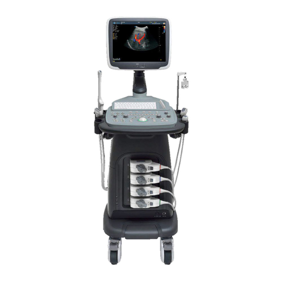
2 System Overview 2�3 System Components Figure 2-1 Right View of the System 1 LCD Monitor 2 Control Panel 3 Coupling Gel Holder 4 Front Handle 5 Transducer Cable Hanger 6 Probe Port 7 Power Indicator 8 Charging/Discharging Indicator 9 Battery Capacity Indicator 10 Caster 11 Footswitch Port 12 Pencil Probe Port... - Page 26 2 System Overview Figure 2-2 Left View of the System 15 Speaker 16 Fan 17 Cable Hanger 18 Dust Filter 19 Peripheral Device Panel 20 DVD Drive 21 USB Port 22 On/Standby Button Basic User Manual...
-
Page 27: Peripheral Device Panel
2 System Overview 2�3�1 Peripheral Device Panel VGA OUT S-VIDEO AUDIO PRINT VIDEO OUT ECG LINE INPUT POWER FUSE 50CT T3.15AH 250V T1 T2 Figure 2-3 Peripheral Device Panel No� Name Description Used for connecting a video device to acquire VGA VGA Video Output signals, such as monitor or projector. -
Page 28: Control Panel
2 System Overview 2�3�2 Control Panel <2> <1> <19> <15> <16> <17> <18> <4> <5> <3> <36> Probe Exam Patient BASELINE FOCUS DEPTH STEER <8> <6> <7> - AUDIO + Body Mark Dual Zoom <24> <25> <20> <21> <22> <23> <33>... - Page 29 2 System Overview No� Name Description Press it to enter the dual split display. <8> Dual Or, press it to activate the desired image in the dual split display. Rotate it to adjust the flow direction in the PW/CW mode. ...
- Page 30 2 System Overview No� Name Description <22> Press it to enter the inactivated PW mode. <23> Press it to enter the PDI mode. <24> Press it to enter the CFM mode. <25> Press it to enter the B mode. Defined as the confirm key. <26>...
- Page 31 2 System Overview No� Name Description <37> MENU Press it to enter the System Setting menu. 2�3�3 Key Panel <5> <6> <7> <8> <9> <10> <11> <12> <13> <14> <15> <16> <1> <2> <3> <4> <19> <17> <30> <18> <29> <19>...
- Page 32 2 System Overview No� Name Description <11> Press it to enter the TDI mode. <12> 3D/4D Press it to enter or exit the 3D/4D mode. <13> Press it to enter the single display. Press it to enter the dual split display. <14>...
-
Page 33: Basic Screen
2 System Overview No� Name Description Press it to display the Exam History screen. <26> Review Or, press it to enter the Review screen when creating a new patient exam. <27> Report Press it to enter the Report screen. <28> Alt GR Reserved function <29>... - Page 34 2 System Overview 7 MI and TIS Indices 8 Application Icon 9 Measured Result Box 10 Color Map (in Color/DPI mode) / Grayscale Map 11 Depth Scale and Focal Position 12 Cine Loop Icon (in frozen mode) 13 Network Connection Status 14 Clipboard 15 Imagining Area 16 Cine Loop Status (in frozen mode)
-
Page 35: Chapter 3 Preparing The System
Chapter 3 Preparing the System System preparation is necessarily performed before you using the ultrasound system. The preparation includes but not limit to moving, positioning or adjusting the system, connecting the probe and the peripheral devices.. -
Page 36: System Assembly
3 Preparing the System 3�1 System Assembly Only service personnel authorized by the manufacturer can assemble the system. Ensure the system is firmly assembled before it is powered on. Figure 3-1 System Assembly 1 M3×8 Screws 2 Control Panel Back Cover 3 M4×10 Screws 4 Monitor Arm 5 Fixing Board... -
Page 37: System Moving/Positioning
3 Preparing the System 3�2 System Moving/Positioning Leave at least 20cm at the back and both sides of the ultrasound system for ventilation. Otherwise, the temperature rise could cause failures. Brake Release (Off) Brake Lock (On) Perform the following steps to position the system. 1. -
Page 38: Connecting And Powering On The System
3 Preparing the System 3�3 Connecting and Powering on the System Two methods can be used to supply power for the system: mains supply and built-in rechargeable lithium battery. When the adapter is connected to the mains supply, the battery is charged until full. 3�3�1 Using the Mains Supply Two switches are provided for the system. -
Page 39: Indicators
3 Preparing the System A fully charged battery can continuously work more than 1 hour. Two batteries are used for system power supply, they must satisfy the following specifications, Nominal voltage: 14.8V Battery capacity: 9.6Ah/142Wh ● Use only the battery when there is an emergency or no reliable mains supply is available. -
Page 40: Powering On/Off The System
3 Preparing the System Indicator Name Mains Supply Battery Supply Green, full capacity Yellow, low capacity Battery Discharging Indicator Blinking yellow, extremely low capacity, the system automatically shuts down and the buzzer beeps. 3�4 Powering On/Off the System ● Do not power off the system during system upgrade or data transmission. ●... -
Page 41: Adjusting The System
3 Preparing the System 3�5 Adjusting the System 3�5�1 Adjusting the Monitor Arm NOTE: ● Be careful with your fingers when adjusting the monitor arm. ● Lock four casters before you adjust the monitor arm. 10cm º º To adjust the monitor vertically, move the upper arm towards to or backwards from the lower arm. -
Page 42: Adjusting The Display Monitor
3 Preparing the System 3�5�2 Adjusting the Display Monitor To swivel the LCD monitor Grip the upper and lower sides of the monitor, tilt the monitor forward or backward. º º Grip the left and right sides of the monitor, swivel the monitor left or right. ... -
Page 43: Connecting The Probe
3 Preparing the System ● Press – to display the setting menu for Contrast. Pressing + can increase the value of the contrast; pressing – can decrease the value. ● Press + to display the setting menu for Brightness. Pressing + can increase the value of the brightness;... -
Page 44: Connecting The Peripheral Device
3 Preparing the System 3�7 Connecting the Peripheral Device 3�7�1 Connecting the Footswitch ● To avoid falling or damage of the footswitch, do not place the footswitch on the ultrasound system. ● Do not use the footswitch other than those provided by the manufacturer. Otherwise, the ultrasound system or the footswitch malfunctions could result. -
Page 45: Connecting The Network Printer
3 Preparing the System 3�7�3 Connecting the Network Printer Printer Setup 1. Connect the printer to the ultrasound system, and turn on the printer. The printer settings are displayed as below. 2. Press OK on the control panel menu of the printer. 3. -
Page 46: Connecting The Usb Printer
3 Preparing the System 3�7�4 Connecting the USB Printer Copy the driver file deskjet�ppd provided by the manufacturer into the directory of the USB drive. Connect the USB drive to the ultrasound system, and then start up the ultrasound system. Press the confirm key to enter the System Setting menu, and click Peripheral. -
Page 47: Chapter 4 Customizing Your System
Chapter 4 Customizing Your System The System Setting menu allows you to specify general system settings, printing, measurement and calculation settings. You can also define the annotation library and shortcut keys. All your customized settings can be saved and can function even after you rebooting the system. -
Page 48: General System Settings
4 Customizing Your System After starting up the ultrasound system, the LCD monitor displays the application mode screen as shown in Figure 6-1. Press the Setup key on the control panel, select System Setting on the pop-up menu to enter the System Setting menu. To make settings in the System Setting menu, ... - Page 49 4 Customizing Your System Item Description Hospital Name Enter the institution name. Select the feature to be enabled after you select the Freeze key. Freeze Response Choose from: Cine, Annot, Calc, Body Mark, Arrow or Caliper. Adjust the sensitivity for the trackball movement. A greater value Trackball Sensitivity brings about the higher sensitivity.
- Page 50 4 Customizing Your System Item Description Enable or disable the annotation-cleared feature after you unfreeze the image in the annotation editing mode. Set it to ON, all annotations are cleared after you press the Freeze Clear Annot On Unfreeze key in the annotation editing mode.
-
Page 51: Display Settings
4 Customizing Your System 4�1�2 Display Settings System Setting General General Display Storage KeyConfig Peripheral Color of ROI Cyan Measure Display Format V1/2 Report Screen Saver DICOM Screen Saver Delay(min) Load Default Annot Font Size Medium About Save&Exit Exit Figure 4-2 General Settings Menu - Display Tab Item Description Set the color for the interest region box. -
Page 52: Storage Settings
4 Customizing Your System 4�1�3 Storage Settings System Setting Storage KeyConfig General Display General Peripheral Clip Format Measure Still Format Report Store Frame Amout 200 DICOM Print & Store Region Parameter& Image&R Load Default Image Share Service OFF About Store to UsbDisk Save&Exit Exit Figure 4-3 General Settings Menu - Storage Tab... -
Page 53: Defined-Key Settings
4 Customizing Your System 4�1�4 Defined-Key Settings System Setting Storage KeyConfig General Display General [Save] [P1] [P2] Peripheral Save Image Save Save Measure Print Image Image Sent to Usb Cine Cine Report Dicom Send Volume Volume DICOM Dicom Print Save Auto Response Save Auto Response Load Default Print Print... -
Page 54: Peripheral Device Settings
4 Customizing Your System 4�2 Peripheral Device Settings You can set the local network, wireless network and printer on this menu. System Setting LocalNetwork Enable Wireless Network Enable General DHCP Static IP Name State Level Peripheral Mr.Wu Conn IP Address Measure Report Netmask... - Page 55 4 Customizing Your System Item Description Click Advance, Speed and Duplex textboxes display on the menu. You can make settings of these items to change the speed and Speed/Duplex communication mode of local network. Click Set to save settings, and then you can click Search to view your settings.
-
Page 56: Measurement Settings
4 Customizing Your System Item Description Net Printer IP Set an IP address of the network printer. Click the button and follow the on-screen instructions to install a printer Add Printer driver. 4�3 Measurement Settings You can make measurement settings on the General, Application and List tabs. 4�3�1 General Measurement Settings System Setting Application... - Page 57 4 Customizing Your System General Measurement Items Item Description In accordance with the setting of this item, the system calculates BSA value automatically after you enter the height and weight of the patient on the Patient Information screen. Choose from: Western or Eastern ...
-
Page 58: Application Settings
4 Customizing Your System Result Position Item Description Dual+Quad Set the position of the result box. Choose from: Right Top, Right Bottom, Left Top, Left Bottom Doppler 4�3�2 Application Settings System Setting Application List General General Application OB Peripheral Measure Auto/Man Trace Shortcut Key... - Page 59 4 Customizing Your System Measurement Setting Set the formula for obstetrics measurement. Item Description Set to display CUA or AUA on the measurement report. CUA/AUA CUA stands for Composite Ultrasound Age, AUA stands for Average Ultrasound Age. Add 1 week to EDD Enable to add one week to EDD.
- Page 60 4 Customizing Your System 2. Select New GA Table or New Growth Table, then click the OK button. Figure 4-8 or Figure 4-9 pops-up. GA Table Measurement Author Deviation -2SD/+2SD -2SD Mean +2SD Meas Unit Meas[mm] -2SD[w+d] Mean[w+d] +2SD[w+d] Save&Exit Exit Figure 4-8 GA Table Growth Table...
-
Page 61: List Settings
4 Customizing Your System 4�3�3 List Settings System Setting Application List General General Application Abdomen Peripheral Measure Caliper Calc List Report Color Doppler DICOM Category Collection Measurement Load Default Default Liver Length About Port.V. Height Width Gallbladder Pancreas Spleen Kidney Renal A Aorta Bladder... -
Page 62: Report Settings
4 Customizing Your System 3. In the List frame, select the imaging mode, then click the Collection or Measurement. 4. Click the Reorder, then adjust the sequence of the collection or measurement on the pop-up screen. 4�4 Report Settings System Setting Logo General Peripheral... -
Page 63: Configuring Dicom
4 Customizing Your System Item Description Context Set the text font size. Background Color Set the background color of the measurement report. Text Color Set the text color. Select items to be displayed on the measurement report. Patient and exam information is displayed on the report by default. Other Display Items for Report information can also be displayed on the report after you tick... - Page 64 4 Customizing Your System Item Description Select the DICOM storage server. Service List Click Add to add a new server and click Delete to delete a server. Remote Host Name Enter the name of DICOM storage server. Set the IP address of the DICOM storage server. IP Address After the setting, click Ping to test the connectivity of the system.
-
Page 65: Commitment Settings
4 Customizing Your System 4�5�2 Commitment Settings You can connect the ultrasound system to the DICOM commitment storage server and make the relevant settings through the Commitment Storage tab. System Setting C-Store General Store Worklist MPPS Print Peripheral Service List StoreCommitment Delete Measure... -
Page 66: Dicom Worklist Settings
4 Customizing Your System Item Description Acse Timeout(sec) Set the timeout time of connecting Acse protocol. Synchronously Receive Tick this item, the ultrasound system receives the N-EVENT-REPORT N-EVENT-REPORT messages synchronously with the storage server. Message Click Echo to verify the connection between the ultrasound system and the DICOM commitment storage server after you make settings about the Remote HostName, IP address, DICOM AE Title, Port Number. - Page 67 4 Customizing Your System Item Description Select the DICOM worklist server. Service List Click Add to add a new server and click Delete to delete a server. Remote Host Name Enter the name of the DICOM worklist server. Set the IP address of the DICOM worklist server. IP Address After the setting, click Ping to test the connectivity of the system.
-
Page 68: Mpps Settings
4 Customizing Your System 4�5�4 MPPS Settings You can connect the ultrasound system to the MPPS server and make the relevant settings through the MPPS tab. System Setting General Store C-Store Worklist MPPS Print Peripheral Service List MPPS Delete Measure DICOM MPPS Report Remote HostName... -
Page 69: Print Service Settings
4 Customizing Your System Click Echo to verify the connection between the ultrasound system and the MPPS server after you make settings about the Remote HostName, IP address, DICOM AE Title, Port Number. A summary displays if the connectivity is verified. 4�5�5 Print Service Settings You can connect the ultrasound system to the print service server and make the relevant settings through the Print Service tab. - Page 70 4 Customizing Your System Item Description DICOM AE Title Set the Application Entity (AE) title of the DICOM print server. Port Number Set the port number of the DICOM print server. Set the print format. Format Choose from: 1×1, 1×2, 2×1, 2×2, 2×3, 2×4, 3×3, 3×4, 3×5, 4×4, 4×5, 4×6 or 5×6.
-
Page 71: Defining System Defaults
4 Customizing Your System Item Description Copies Set the number of copies to print. Film Session Label Enter a name to be applied on a group of the film labels. Smoothing Type Set the value of magnification interpolation for the printer. Click Echo to verify the connection between the ultrasound system and the DICOM print server after you make settings about the Remote HostName, IP address, DICOM AE Title, Port Number. - Page 72 4 Customizing Your System To load system defaults 1. Click Load, select a setting name, and then a dialogue box appears. 2. Type Y on the control panel to confirm the loading; Or, type N on the control panel to cancel the loading; Press the Delete key on the control panel to delete the system defaults.
-
Page 73: Viewing System Information
4 Customizing Your System 4�7 Viewing System Information Press the Setup key on the control panel, select About on the pop-up menu to enter the System Information menu. You can view the current hardware version, the software version and the control number. The control Number is a unique number for the ultrasound system. - Page 74 This page is intentionally left blank.
-
Page 75: Chapter 5 Preparing For An Exam
Chapter 5 Preparing for an Exam You can start an exam without entering any patient information. However, the patient’s name and ID are closely related with each patient’s image. To avoid patient identification errors, you should always verify the identification with the patient. -
Page 76: Acquiring Patient Information
5 Preparing for an Exam 5�1 Acquiring Patient Information You can acquire the patient information in the following ways: Create new patient information Retrieve archived patient information Receive patient information using DICOM worklist 5�1�1 Beginning a New Patient Press the Patient key on the control panel to display the Patient Information screen. - Page 77 5 Preparing for an Exam Name Enter manually first name, middle name or last name of the patient. Enter manually the date of birth for the current patient. You can set Date Format on the General Settings menu. The patient’s age will be automatically calculated if you enter the information in the DOB textbox.
-
Page 78: Retrieving Archived Information
5 Preparing for an Exam 5�1�2 Retrieving Archived Information You can retrieve the archived information by choosing the Patient key -> Patient List -> Exam Review. Press the Menu key on the control panel, and then select Exam History on the prompt menu. Patient Exam List Patient ID Last Name... -
Page 79: Using Dicom Worklist
5 Preparing for an Exam Patient Exam List Patient ID Last Name Search First Name Date 05/04/2014 To Reset 05/05/2014 Patient Review Current Exam Patient ID Patient Name Birth Date Sex Exam Date/Time Image Size 20140505 Mary Unknown 05/05/2014-16:04:03 40.82M New Patient DICOM Queue PPS Screen... -
Page 80: Completing An Exam
5 Preparing for an Exam 5�3 Completing/Discontinuing an Exam 5�3�1 Completing an Exam 1. Press the End Exam key on the control panel. A dialogue box pops up as follows: Do you wish to end the current exam? Cancel 2. Click OK to end the exam. 5�3�2 Discontinuing an Exam 1. -
Page 81: Chapter 6 Acquiring Images
Chapter 6 Acquiring Images You can acquire images by optimizing the relevant parameters for clinical diagnosis. -
Page 82: Selecting A Probe And An Exam Type
6 Acquiring Images 6�1 Selecting a Probe and an Exam Type Once the ultrasound system is started up, the LCD monitor displays the available probes and the exam types (as shown in Figure 6-1). You can select the desired probe by using the trackball. You can also press the Probe key to enter the application mode screen from other screens. - Page 83 6 Acquiring Images 4. Press the Y key to enter the User preset screen. Create preset Probe L741 Presets display Exam Name Exam Type < > Vascular Exam Icon C-Vascular < > Create Exam Replace Exam Exit Figure 6-2 User Preset Menu 5.
-
Page 84: Acquiring B-Mode Images
6 Acquiring Images ● Click one desired application preset, click to arrange the preset on the application mode screen. ● Click one desired application, click Delete -> Yes to delete the application preset. ● Click Restore Factory Default -> Yes in the pop-up dialogue box to restore defaults. 6�2 Acquiring B-Mode Images B-mode imaging is intended to provide information of anatomical structure of soft tissue. -
Page 85: Optimizing B-Mode Images
6 Acquiring Images 6�2�2 Optimizing B-Mode Images After entering the B mode, press the MENU key on the control panel, the screen displays all controls related to the B-mode imaging, you can use them to optimize B-mode images. NOTE: All parameters can only be adjusted in a real time B mode, but Chroma can also be adjusted in the frozen mode. -
Page 86: Focal Position/Number/Span
6 Acquiring Images 6�2�2�4 Focal Position/Number/Span The focal position/number/span is used to tighten up the beam for a specific area and the focus identified by a red triangle displays in the right corner of the image. Focus optimizes the image by increasing the resolution for a specific area. To adjust focal position/number/span: ... -
Page 87: Compound Imaging
6 Acquiring Images 3. Rotate the MENU knob or press the left/right arrow key to choose a color scheme. 6�2�2�8 Compound Imaging Compound imaging is used to acquire a series of overlapping image frames from substantially differing spatial directions and combining these images to reduce speckle and improve contrast resolution. -
Page 88: Grayscale Curve
6 Acquiring Images 6�2�2�12 Grayscale Curve Grayscale curve optimizes the brightness of each pixel in accordance with the corresponding echo. To adjust the grayscale curve: 1. Press the MENU key in the real-time mode to display a menu. 2. Use the trackball or press the up/down arrow key to select GSC on the pop-up menu. 3. -
Page 89: Tissue Acoustic Characteristics
6 Acquiring Images 6�2�2�16 Tissue Acoustic Characteristics Tissue acoustic characteristics refer to the speed of ultrasound passing through the tissue. Tissue acoustic characteristics optimize the image used for measurements and calculations. The greater tissue acoustic characteristics bring about the quicker speed of ultrasound. To adjust tissue acoustic characteristics: 1. -
Page 90: Steer
6 Acquiring Images 6�2�2�20 Steer Steer can be adjusted to change the direction of the acoustic beam when performing a real time scan by using the linear probes. To adjust the steer: Flip the STEER switch to left or right to change the direction of the acoustic beam. NOTE: Only the linear probes are available when adjusting the steer. -
Page 91: Pdi Mode
6 Acquiring Images 6�3�2 PDI Mode PDI (Power Dropper Imaging) is a color flow imaging technology which adds the flow signal in the CFM-mode image. PDI uses the number and amplitude of red blood cell going through in the flow to create the color-coded imaging. -
Page 92: Tdi Mode
6 Acquiring Images 6�3�3 TDI Mode NOTE: TDI imaging is only applied to cardiac applications by using the phased probes. TDI (Tissue Droppler Imaging) is a color flow imaging technique which detects the low frequency signal reflected from cardiac muscle. TDI provides the flow information of velocity and direction for cardiac movement. -
Page 93: Optimizing Cfm/Pdi/Tdi Mode Images
6 Acquiring Images 6�3�4 Optimizing CFM/PDI/TDI Mode Images After entering the CFM/PDI/TDI mode, press the MENU key on the control panel, the monitor displays all controls related to the CFM/PDI/TDI mode imaging, you can use them to optimize CFM/ PDI/TDI-mode images. NOTE: All parameters can be adjusted in a real time CFM/PDI/TDI mode, Baseline... -
Page 94: Baseline
6 Acquiring Images A lower line density is useful in fetal heart beat, adult cardiac applications and in clinical Radiology applications. A higher line density is useful in obtaining very high resolution, such as thyroid, testicles. To adjust the line density: 1. -
Page 95: Sector Position/Width/Angle
6 Acquiring Images 3. Rotate the MENU knob or press the left/right arrow key to adjust the value. 6�3�4�9 Sector Position/Width/Angle Sector width (for linear probes) or sector angle (for curved and phased probes) is used to adjust the frame rate. You can adjust the sector width or angle to get more information without moving the probe. -
Page 96: Flow Invert
6 Acquiring Images NOTE: Only the linear probes are available when adjusting the steer. 6�3�4�13 Flow Invert Flow invert is used to view blood flow from a different perspective. When Flow Invert is set to OFF, red pixels represent flow to the probe; blue pixels represent flow away from the probe. - Page 97 6 Acquiring Images 3. Adjust the M line by using the trackball. 4. Press the Update key on the control panel to activate the M mode. The basic screen displays as below after being activated. Y-axis: depth X-axis: time Figure 6-9 M-Mode Imaging Screen ...
-
Page 98: Anatomical M-Mode
6 Acquiring Images 6�4�2 Anatomical M-Mode Anatomical M-mode is used for fetal cardiac applications. Anatomical M-mode can be used with phases array probes when performing cardiac exams or convex probes when performing abdomen exams. In the anatomical M-mode, the M-mode cursor can be positioned perpendicular to the anatomical structure and be adjusted 360°... -
Page 99: Gain
6 Acquiring Images 6�4�3�1 Gain M gain controls the overall brightness of the M trace. To adjust the gain: Rotate the GAIN knob on the control panel clockwise to increase the value. Rotate the GAIN knob on the control panel anticlockwise to decrease the value. 6�4�3�2 M Process M process is used to set the processing method for the M trace display. -
Page 100: Power
6 Acquiring Images 6�4�3�6 Power Power is used to select the amount of ultrasound acoustic power produced by the probe. The adjustment range of the power is 30%-100%, and ±10% can be adjusted each time. The real time value of the power is displayed in the imaging information area of the basic screen. To adjust the power: 1. - Page 101 6 Acquiring Images 2. Press the PW key on the control panel to enter the inactivated B+PW mode 1. Secptral Doppler Line Flow Cursor Sample Volum Gate 2D Imaging Figure 6-11 Inactivated B+PW Mode 1 Imaging Screen The Spectral Doppler line and the sample volume gate are used to locate the qualitative analysis on the image.
- Page 102 6 Acquiring Images The basic screen displays as below after being activated. Spectral Doppler Line Flow Cursor Sample Volume Gate 2D Imaging cm/s Y-axis: Frequency X-axis: Time Figure 6-12 PW-Mode Imaging Screen X-axis is the time scale. Y-axis is Doppler frequency scale, including positive and negative indicators. Rotate the AUDIO knob on the control panel to adjust the audio volume.
-
Page 103: Cw Mode
6 Acquiring Images If needed, press the Update key on the control panel to enter the inactivated B+PW mode 2, the following screen appears. cm/s Y-axis: Frequency X-axis: Time Figure 6-13 Inactivated B+PW Mode 2 Imaging Screen You can also adjust the position and angle of spectral Doppler line, the size of sample volume gate, and the direction of the flow cursor. - Page 104 6 Acquiring Images The Spectral Doppler line and the sample volume gate are used to locate the qualitative analysis on the image. The flow cursor needs to be adjusted parallel to the flow when measuring the velocity. 3. Adjust the position and angle of the Spectral Doppler line. ...
-
Page 105: Optimizing Spectral Doppler Images
6 Acquiring Images If needed, press the Update key on the control panel to enter the inactivated B+CW mode 2, the following screen appears. cm/s Y-axis: Frequency X-axis: Time Figure 6-16 Inactivated B+CW Mode 2 Imaging Screen You can also adjust the position and angle of spectral Doppler line, and the direction of the flow cursor. -
Page 106: High Pulse Repetition Frequency
6 Acquiring Images The range of PRF value varies with the probe model and the exam type. To adjust the pulse repetition frequency: Flip the PRF switch upwards to increase the value. Flip the PRF switch downwards to decrease the value. NOTE: The value of wall filter is also changed when adjusting PRF. -
Page 107: Frequency
6 Acquiring Images 6�5�3�6 Frequency The probe is capable of generating a broadband signal with a certain frequency and bandwidth. At deeper position of Doppler imaging, the frequency optimizes the edges. To adjust the frequency: 1. Press the MENU key in the M mode to display a menu. 2. -
Page 108: Display Format
6 Acquiring Images To adjust the dynamic range: 1. Press the MENU key in the M mode to display a menu. 2. Use the trackball or the up/down arrow key to select DYN on the pop-up menu. 3. Rotate the MENU knob or press the left/right arrow key to adjust the value. 6�5�3�11 Display Format Display format is used to view the image better. -
Page 109: Simult
6 Acquiring Images 6�5�3�15 Simult Simult is used to synchronously display two real time scans in the 2D and the PW modes. To enable or disable the feature: Tap Simult in the activated PW mode or in the inactivated B+PW mode 2, the two real time scans in the 2D and the PW modes are displayed. -
Page 110: B+Cfm/Dpi/Tdi +Pw
6 Acquiring Images The basic screen displays as below after being activated. Y-axis: depth X-axis: time Figure 6-18 B+CFM/TDI +M-Mode Imaging Screen X-axis is the time scale. Y-axis is the depth scale. 5. Optimize M-mode image. For details, refer to Section 6.4.3 Optimizing M-Mode Images. 6. - Page 111 6 Acquiring Images 3. Adjust the position and angle of the Spectral Doppler line. Position the sample volume gate on the Spectral Doppler line by moving the trackball upwards or downwards. Adjust the angle of the Spectral Doppler line by moving the trackball to the left or the right. 4.
-
Page 112: B+Cfm/Dpi+Cw
6 Acquiring Images If needed, press the Update key on the control panel to enter the inactivated CFM/PDI/TDI+PW mode 2, the following screen appears. cm/s Y-axis: Frequency X-axis: Time Figure 6-21 Inactivated CFM/PDI/TDI+PW Mode 2 Imaging Screen You can also adjust the position and angle of spectral Doppler line, the size of sample volume gate, and the direction of the flow cursor. -
Page 113: Chapter 7 Elastography Imaging
Chapter 7 Elastography Imaging As an adjunct technique for clinical practice, the elastography determines if an area of tissue is hard or soft as compared with its surroundings. Furthermore, it provides the elastography image to discover tumors (stiffer than the surrounding tissue). The elastography image displays a range of map shades from the softest tissue in the image to the stiffest in a given field of view. -
Page 114: Acquiring Elastography Images
7 Elastography Imaging NOTE: Elastography imaging is only available performed with L741 probe. 7�1 Acquiring Elastography Images Perform the following steps to acquire the eastography image. 1. Select L741 and Small Parts as the desired probe and exam type, the system automatically enters the real-time B mode. -
Page 115: Optimizing Elastography Images
7 Elastography Imaging Operation Concerns: Ensure the compression is applied perpendicularly, and all parts of the target lesion are compressed uniformly. Ensure the compression is a dynamic intermittent force, i.e. alternate tension with relaxation, which could keep the distorted tissue back to normal status. If the distorted tissue is not relaxed, the tissue cannot be distorted and the elastography imaging cannot be performed. -
Page 116: Strain Process
7 Elastography Imaging 7�2�2 Strain Process Strain process is used to set relative parameters of elastography algorithm, the elastography image varies with this setting. To adjust the strain process: 1. Press the MENU key to display a menu. 2. Use the trackball or press the up/down arrow key to select Strain Process on the pop-up menu. 3. -
Page 117: Working With Elastography Images
7 Elastography Imaging 7�3 Working with Elastography Images You can work with the elastography images by using the features in the frozen mode, such as cine review, annotations, data storage or measurement. For details, refer to Section 10.4 Using Cine, Section 10.5 Annotations and Body Marks, Chapter 11 Managing Images/Data and the relevant sections in Advanced User Manual. - Page 118 This page is intentionally left blank.
-
Page 119: Chapter 8 3D Imaging
Chapter 8 3D Imaging 3D imaging allows you to see width, height and depth of the anatomical structure. 3D imaging can be performed by all probes, but the quality of images is closely related to 2D imaging. 3D imaging mainly applies to obstetric exams, and can be used to see the three dimensional volume image of internal organs or fetus. -
Page 120: Acquiring 3D Images
8 3D Imaging 8�1 Acquiring 3D Images The following description uses 3D imaging performed with the VC6-2 probe as an example. Perform the following steps to acquire 3D images. 1. Enter the patient information, select VC6-2 probe and an exam type (such as obstetric exam throughout this chapter) to enter the B mode. - Page 121 8 3D Imaging 7. Select the Menu key, set User Mode, Render Mode, Image Quality, Sweep Angle or Stabiliza- tion in the pop-up menu. For other parameters, refer to Section 8.2 Working with 3D Images. 8. Press the Freeze key on the control panel to display the 3D imaging. ...
-
Page 122: Working With 3D Images
8 3D Imaging 8�2 Working with 3D Images You can review, optimize or save 3D images. 8�2�1 Adjusting ROI You can crop 3D image by adjusting ROI on reference images to remove areas outside from interest area. This feature is suitable for cropping regular reviews. Perform the following steps to crop a review. -
Page 123: Setting Display Format
8 3D Imaging NOTE: Selecting Hide ROI can disable the ROI. 8�2�2 Setting Display Format The system automatically enters the 3D imaging in a quad display by default. You can press the 1, 2 or 4 key on the key panel to enter the full, dual or quad split display. 8�2�3 Setting Render Mode Vol, MaxIP and X-ray can be set. -
Page 124: Moving/Rotating/Magnifying Images
8 3D Imaging 5. Move the cursor on the image by using the trackball, press the confirm key on the control panel, and then trace the border of the object. 6. Press the confirm key to acquire the desired image In the following figure, Trace Cut is set to In NOTE: Selecting Undo Cut can restore the cutting by using Trace Cut. -
Page 125: Optimizing 3D Image
8 3D Imaging ● Press the MENU key to display a menu, press the up/down arrow key to select Orientation on the pop-up menu, and then rotate the MENU knob or press the left/right arrow key to rotate all images by 0º, 90º, 180º or 270º. ●... -
Page 126: Observing Reviews By The Slice
8 3D Imaging 8�2�7 Observing Reviews by the Slice You can observe reviews by using two or more slices. For example, each layer of an irregular tumor can be observed by applying this feature. Perform the following steps to observe a review. 1. -
Page 127: Setting The Scan Mode
8 3D Imaging 8�2�8 Setting the Scan Mode You can set the scan method in accordance with your actual use. 1. Press the MENU key in the 3D mode to display a menu. 2. Press the up/down arrow key to select Scan Mode on the pop-up menu. 3. -
Page 128: Measurement
8 3D Imaging 8�2�12 Measurement You can perform the distance, trace or volume measurement on View A, B or C. To perform the measurement in the 3D mode: 1. Press the MENU key in the 3D mode to display a menu. 2. -
Page 129: Chapter 9 4D Imaging
Chapter 9 4D Imaging 4D imaging enables the display of the real time 3D anatomical structure. 4D imaging only can be performed by the compatible volume probes. 4D imaging adds the dimension of “movement” to a 3D image by providing continuous, real-time displays of internal organs or fetus. -
Page 130: Entering The Real-Time 4D Imaging
9 4D Imaging 9�1 Acquiring 4D Images The following description uses 4D imaging performed with the VC6-2 probe as an example. 9�1�1 Entering the Real-Time 4D Imaging Perform the following steps as follows. 1. Enter the patient information, select VC6-2 probe and an exam type (such as obstetric exam throughout this chapter) to enter the B mode. -
Page 131: Acquiring Dynamic 3D Image
9 4D Imaging For other parameters, refer to Section 8.2 Working with 3D Images. 8. Press the 1, 2 or 4 key on the key panel to enter the full, dual or quad display. Or, you can also press the Freeze key in the 3D mode to enter the 4D mode. The imaging area of the screen is divided into 3 reference images and a dynamic 3D image by default. -
Page 132: Working With 4D Images
9 4D Imaging 9�2 Working with 4D Images You can review, optimize or save 4D images in the frozen mode. For details, refer to Section 8.2.6 Optimizing 3D Image. Basic User Manual... -
Page 133: Chapter 10 Working With Images
Chapter 10 Working with Images You can work with the acquired images by using the features provided by the ultrasound system, such as the split display, panoramic display and annotations. -
Page 134: Imaging Features
10 Working with Images 10�1 Imaging Features 10�1�1 Imaging Reverse Press on the key panel to reverse the real time scan left or right. Press on the key panel to reverse the real time scan up or down. 10�1�2 Split Display You can position two or four images side by side on the screen to compare the images by using the split display. -
Page 135: M-Tuning
10 Working with Images The image is spitted by two parts with two real time scans. 1 .0 cm/s 1/50 Figure 10-2 Real Time CFM + Real Time B Quad-Split Display 1. Press the B, CFM, PDI or TDI key on the control panel to enter the real time scan. 2. -
Page 136: Harmonic Imaging
10 Working with Images Press the m-Tuning key on the key panel to enable this feature. Or, press m-Tuning again to disable this feature. 10�1�4 Harmonic Imaging Tissue Harmonic Imaging (THI) uses the harmonic frequencies generated by tissue. The fundamental transmit frequency results in a harmonic frequency echo. - Page 137 10 Working with Images NOTE: ● Panoramic imaging is only available performed with linear or curved probes. ● Apply adequate amount of coupling gel along the intended path of the scan. ● Do not shake, rotate or tilt the probe during the scan. ●...
- Page 138 10 Working with Images 6. Work with the image. ● Magnify the Image a. Press the MENU key on the control panel to display a menu. b. Select ZOOM on the pop-up menu, and a ROI appears on the thumbnail. c.
-
Page 139: Magnifying An Image
10 Working with Images ● Select Rotate on the pop-up menu, and rotate the MENU knob or press the left/right arrow to rotate the image. ● Select Overview on the pop-up menu, and rotate the MENU knob or press the left/right arrow to restore the image to the default setting. -
Page 140: Cutting Cine
10 Working with Images Or, you can press the MENU key, use the trackball or press the up/down key to select F By F on the pop-up menu, and then rotate the MENU knob or press the left/right arrow key to review the cine frame by frame. -
Page 141: Annotating An Image With Arrows
10 Working with Images To input the annotation manually Input the desired annotation by using the keyboard. After finishing, press the confirm key to add the annotation on the image. To move the annotation Move the cursor on one annotation. Press the confirm key to activate this annotation and move it to the desired place by using the trackball. -
Page 142: Deleting Annotations And Body Marks
10 Working with Images 10�5�4 Deleting Annotations and Body Marks To delete annotations If an annotation is being edited, you can press the Clear key on the control panel to delete it from the screen. If an annotation has been edited and the ultrasound system exits the editing mode, you can firstly press the Annot key on the control panel, move the cursor on the annotation by using the trackball, and then press the confirm key to select it. -
Page 143: Basic Procedures Of Ecg Operation
10 Working with Images 10�6�1 Basic Procedures of ECG Operation Perform the steps as follows: 1. Power off the ultrasound system, and connect the ECG cable to the specific port of the ultrasound system. 2. Power on the ultrasound system, and attach the ECG electrodes on the patient’s body (as shown in the following figure). -
Page 144: Reviewing Ecg
10 Working with Images Item Description ECG Invert Enable or disable the waveform inversion function. Enable or disable the R-trigger function. When enabled, R-Trigger menu pops up, the menu contains Trigger Delay, Frame Count, and Frame Int. R-Trigger NOTE: In order to enable the R-trigger function, you should disable the com- pounding imaging function first. -
Page 145: Chapter 11 Managing Images/Data
Chapter 11 Managing Images/Data Images in this ultrasound system include frame images and cine, you can save or review them after the acquisition. Meanwhile, images can be also backed up to the USB device or DVD for future review if it is needed. -
Page 146: Storing An Image
11 Managing Images/Data 11�1 Storing an Image NOTE: ● Keys can be defined on the General Settings menu - Key Configuration tab. For details, refer to 4.1.4 Defined-Key Settings. ● All data are saved to the ultrasound system by default. If the USB drive is connected and Store to UsbDisk is ticked on the General Settings menu - Key Configuration tab, the saved data will be synchronously stored to the USB drive. -
Page 147: Retrieving An Image
11 Managing Images/Data To view the image on the View Image screen 1. Press the Review key on the control panel to enter the View Image screen. The screen is displayed with images and cine thumbnails. View Image Exam Patient ID:345 Patient Name: Mary Files Number: 19 All Select... -
Page 148: Sharing Data
11 Managing Images/Data 11�3 Sharing Data You can remote access to the data stored in the system through a computer. Perform the steps as follows. 1. Connect the computer to the ultrasound system. 2. Set Image Share Service to On on the General Settings menu - Storage tab. 3. -
Page 149: Importing Data To The System
11 Managing Images/Data 6. Click Patient Export to back up all data relevant to the patient. DVD ejects after a successful prompt is displayed. 7. Take out DVD from the CD-ROM and close the tray. If only images are needed to be exported, you can export them on the View Image screen. 11�5 Importing Data to the System NOTE: ●... - Page 150 This page is intentionally left blank.
-
Page 151: Chapter 12 Working With Dicom
Chapter 12 Working with DICOM DICOM (Digital Imaging and Communications in Medicine) is a standard created by National Electrical Manufacturers Association (ACR-NEMA) to regulate the distribution and viewing of medical images such as ultrasound images and cine. If the ultrasound system is configurated the DICOM module, you can: ... -
Page 152: Verifying Connectivity
12 Working with DICOM 12�1 Verifying Connectivity Perform the steps as follows. 1. Access the ultrasound system to the local network of DICOM servicer by using an Ethernet cable. 2. Make the relative settings about the local network and DICOM server. For details, refer to Section 4.8 Configuring DICOM. -
Page 153: Dicom Worklist
12 Working with DICOM 2. Press the Save, P1 or P2 key in the real-time or frozen mode to send the current image to DICOM printer server. To print patient data 1. Connect the USB drive to the ultrasound system. 2. -
Page 154: Mpps
12 Working with DICOM Perform the steps as follows. 1. Search for the patient information Enter the search requirements, such as Patient Name, Patient ID, Accession#, Exam Date/Time or Requested Procedure ID, and then click Search to search the desired one. Clicking Reset can clear all the search information. - Page 155 12 Working with DICOM PPS Screen Information Patient ID Patient Name Birth Date Sex Description Date/Time State 20140505 Mary Unknown IN PROGRESS Scheduled Procedure Step Information Code Description Meaning Append Exit Figure 12-2 PPS Screen The PPS screen displays MPPS information about the current patient. If the patient information is acquired from the DICOM WorkList, the PPS screen will also display the relevant acquisition protocol.
-
Page 156: Storage Commitment
12 Working with DICOM 12�6 Storage Commitment Storage commitment is used to confirm whether the images or structured reports are successfully stored to the DICOM storage server. If you want to check the sending status, choose the Patient key -> Patient List -> DICOM Queue. 12�7 DICOM Queue DICOM Log is used to check the sending state of DICOM storage, DICOM print, MPPS. -
Page 157: Chapter 13 Probes And Biopsy
Chapter 13 Probes and Biopsy You should be thoroughly familiar with the operations of the probe and the biopsy bracket before using them. To ensure the performance and availability of the probe and the biopsy bracket, you should also periodically check, clean, disinfect or maintain them. -
Page 158: Probe
13 Probes and Biopsy NOTE: A general instruction for the probe and the biopsy bracket is provided in this manual. For details, refer to the relevant manuals. 13�1 Probe This ultrasound system supports a wide range of transducers which make the system remarkably versatile. -
Page 159: Probe Usage
13 Probes and Biopsy 13�1�2 Probe Usage ● Do not use the probes other than those provided by the manufacturer. Otherwise, the ultrasound system cannot be performed, and an accident such as a fire may result in the worst case. ●... -
Page 160: Cleaning The Probe
13 Probes and Biopsy 3. Orient the probe Check the probe orientation mark before the scan. The image acquired from the mark side of the probe is displayed on the monitor. 4. Perform a scan. Intraoperative probe usages 1. Wear medical sterile gloves. 2. -
Page 161: Disinfecting And Sterilizing The Probe
13 Probes and Biopsy Perform the following steps to clean the probe. 1. Disconnect the probe from the ultrasound system, and remove the probe sheath and the biopsy bracket from the probe. 2. Use a lint-free soft cloth dampened with mild soapy water to wipe the probe. ... - Page 162 13 Probes and Biopsy Disinfection Levels To choose an appropriate disinfectant, you first must determine the required level of disinfection, based on the probe applications. Level of Classification Definition Application Disinfection Intraoperative, A device that enters normally sterile Critical Sterilization biopsy use or blood tissue or the vascular system.
- Page 163 13 Probes and Biopsy Table 13-1 Recommended Method for Medium-level Disinfection Level for Active Contact Disinfectant Manufacturer Active Ingredients Contact Type Ingredient Period 70% Isopropyl alcohol All 70% Isopropyl alcohol 70% Spray/Wipe <10 minutes T-spray II Pharm. Inc. Quat.Ammonia Spray/Wipe <10 minutes T-spray Pharm.
-
Page 164: Disinfecting And Sterilizing The Probe Cable
13 Probes and Biopsy Table 13-3 Recommended Method for Sterilization Level for Active Sterilant Manufacturer Active Ingredients Contact Type Contact Period Ingredient Cidex™ Activated J&J Glutaraldehyde 2.4% Soak 10 hours Dialdehyde Solution 13�1�5 Disinfecting and Sterilizing the Probe Cable ● Do not immerse the probe connector or handle into disinfectant or sterilant. ●... -
Page 165: Storage And Transportation
13 Probes and Biopsy 13�1�6 Storage and Transportation Store and transport the probe to ensure the probe is in a good condition. To transport the probe 1. Ensure the probe is cleaned and disinfected before the transportation. 2. Place the probe fully into the carrying case, and carefully wind the cable. 3. -
Page 166: Available Biopsy Brackets
13 Probes and Biopsy 13�2�1 Available Biopsy Brackets Biopsy Available Available Biopsy Needle Application Bracket Model Probe Model NGBC322 C322 14G, 16G, 18G, 20G, 22G Body surface NGBC344 C344 14G, 16G, 18G, 20G, 22G Body surface NGBC354 C354 14G, 16G, 18G, 20G, 22G Body surface NGBC611 C611... - Page 167 13 Probes and Biopsy Perform the steps as follows: 1. Ensure there is no damage, deformation, malfunction, loose or missing some parts on the biopsy bracket before the assembly. 2. Wear sterile gloves. 3. Unfold the probe sheath, and apply an appropriate amount of coupling gel to the inside of the sheath and onto the face of the probe.
- Page 168 13 Probes and Biopsy To assemble the intracavitary biopsy bracket Top Housing Inner Part Perform the steps as follows: 1. Ensure there is no damage, deformation, malfunction, loose or missing some parts on the biopsy bracket before the assembly. 2.
-
Page 169: Preparing For A Biopsy
13 Probes and Biopsy 11. Unfold another probe sheath, and apply an appropriate amount of coupling gel to the inside of the sheath. 12. Hold the probe attached with the biopsy bracket and unroll the sheath onto them. 13�2�3 Preparing for a Biopsy You should prepare the following items before performing the biopsy. - Page 170 13 Probes and Biopsy If you want to adjust the biopsy guidelines, you can press the MENU key, select Biopsy Cali� on the pop-up menu, and then rotate the MENU knob or press the left/right arrow key to display the biopsy calibration menu.
-
Page 171: Cleaning The Biopsy Bracket
13 Probes and Biopsy 13�2�6 Cleaning the Biopsy Bracket ● Clean the biopsy bracket after each use. ● Wear medical sterile gloves and protective goggle during the cleaning. Perform the steps as follows: 1. Disconnect the probe from the ultrasound system, and remove the biopsy bracket and biopsy guide tube from the probe. -
Page 172: Storage
13 Probes and Biopsy Table 13-5 Recommended Method for Sterilization Level for Active Sterilant Manufacturer Active Ingredients Contact Type Contact Period Ingredient Cidex™ Activated J&J Glutaraldehyde 2.4% Soak 10 hours Dialdehyde Solution 13�2�8 Storage Store the biopsy bracket in a sterile environment. Basic User Manual... -
Page 173: Chapter 14 System Maintenance
Chapter 14 System Maintenance To maintain the safety and functionality of the ultrasound system, you should periodically perform the maintenance for the ultrasound system and accessories. -
Page 174: Cleaning The System
14 System Maintenance ● To avoid electrical shock and damage to the ultrasound system, power off and unplug the system from the AC power outlet before cleaning. ● To maintain the safety and functionality of the ultrasound system, maintenance must be performed at least every 1 year. -
Page 175: Maintenance Checks
14 System Maintenance To clean the trackball 1. Power off and unplug the ultrasound system from the AC power outlet. 2. Press the bulges in the ring by both hands. 3. Turn the ring anticlockwise until the ring lifts. 4. -
Page 176: Troubleshooting
14 System Maintenance Control of foot brake Connectivity of interfaces 3. Image Recording Images in each mode Image recording using the standard transducer 14�3 Troubleshooting A1: The ultrasound system cannot be started up. Q1: Check whether the ultrasound system is plugged in, the main power switch is located to position and the fuse is intact. -
Page 177: Equipment Disposal
14 System Maintenance 14�5 Equipment Disposal You should dispose of the main unit, the probe, the biopsy bracket or other accessories in accordance with the local laws or regulations. For the detailed disposal information, consult the manufacturer or the local distribution. The manufacturer is not responsible for any system content or accessories that have been discarded improperly. - Page 178 This page is intentionally left blank.
- Page 179 Appendix A Specifications EN 60601-1 (IEC 60601-1), Medical electrical equipment Part 1: General requirements for basic safety and essential performance, Class I, BF, continuous operation EN 60601-2-37:2008 (IEC 60601-2-37:2007), Medical Electrical Equipment Part 2-37: Particular Requirements for the Basic Safety and Essential Comply with Performance of Ultrasonic Medical Diagnostic and Monitoring Equipment EN 60601-1-2:2007 (IEC 60601-1-2: 2007), Class A, Medical electrical...
- Page 180 This page is intentionally left blank.
-
Page 181: B.1 Electromagnetic Emissions
Appendix B EMC Guidance and Manufacturer’s Declaration B1 Electromagnetic Emissions The equipment is intended for use in the electromagnetic environment specified below. The customer or the user of the EQUIPMENT should assure that it is used in such an environment. Emissions Test Compliance Electromagnetic Environment and Guidance... -
Page 182: B.2 Electromagnetic Immunity
B2 Electromagnetic Immunity The equipment is intended for use in the electromagnetic environment specified below. The customer or the user of the equipment should assure that it is used in such an environment. Electromagnetic Environment and Immunity Test IEC 60601 Test Level Compliance Level Guidance Electrostatic ±6 kV Contact... - Page 183 The equipment is intended for use in the electromagnetic environment specified below. The customer or the user of the equipment should assure that it is used in such an environment. IEC 60601 Compliance Immunity Test Electromagnetic Environment and Guidance Test Level Level Conducted RF 3Vrms...
-
Page 184: B.3 Recommended Separation Distances Between Portable And Mobile Rf Communications Equipment And The Equipment
B3 Recommended Separation Distances between Portable and Mobile RF Communications Equipment and the Equipment The equipment is intended for use in an electromagnetic environment in which radiated RF disturbances are controlled. The customer or the user of the equipment can help prevent electromagnetic interference by maintaining a minimum distance between portable and mobile RF communications equipment (transmitters) and the equipment as recommended below, according to the maximum output power of the communications equipment. - Page 185 Appendix C In Situ, Derated, and Water Value Intensities All intensity parameters are measured in water. Since water absorbs very little acoustic energy, these water measurements represent a worst case value. Biological tissue does absorb acoustic energy. The true value of the intensity at any point depends on the amount and type of tissue and the frequency of the ultra-sound that passes through the tissue.
- Page 186 This page is intentionally left blank.
-
Page 187: Appendix D Acoustic Output Data
Appendix D Acoustic Output Data Please consult the accompanying CD. - Page 188 P/N: 4710.01146X01 4710.00449A04 MEDISONO LLC 3511 Silverside RD. Wilmington, DE 19810, USA Email: info@medisono.com (305)406-3931 Fax: (305)406-2144...
Need help?
Do you have a question about the P12 EXP and is the answer not in the manual?
Questions and answers