Advertisement
Quick Links
ASCON spa
ISO 9001
C e r t i f i e d
ASCON spa
via Falzarego, 9/11
20021 Bollate
(Milano) Italy
Fax +39 02 350 4243
http://www.ascon.it
e-mail support@ascon.it
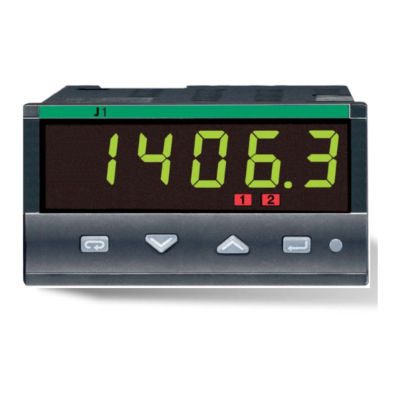
Two alarms indicator
1
/
DIN - 96 x 48
8
J1 line
U s e r M a n u a l • M . I . U . J 1 - 3 / 0 9 . 0 2 • C o d . J 3 0 - 4 7 8 - 1 A J 1 I E
c
c
Advertisement

Related Manuals for ascon Gammadue Series

Summary of Contents for ascon Gammadue Series
- Page 1 J1 line ASCON spa U s e r M a n u a l • M . I . U . J 1 - 3 / 0 9 . 0 2 • C o d . J 3 0 - 4 7 8 - 1 A J 1 I E...
- Page 2 Two alarms indicator DIN - 96 x 48 J1 line 1406. 3...
- Page 3 Information Please, read these instructions carefully before proceeding with the installation of the controller. Class II instrument, rearl panel mounting. OTES This indicator has been designed in compliance with: ON ELECTRIC Regulations on electrical apparatus (appliance, systems and installations) according to SAFETY AND the European Community directive 73/23/EEC amended by the European Community direc- ELECTROMAGNETIC...
- Page 4 Table of contents TABLE OF CONTENTS Operating mode Resources Alarms Page NSTALLATION ........... Page LECTRICAL CONNECTIONS ..... option Main universal input Page RODUCT CODING ........Page OP1 OP2 PERATIONS ............Page ISPLAYS ............... Page OMMANDS ............Page ECHNICAL SPECIFICATIONS ... Modbus RS485 Special functions Parameterisation...
- Page 5 1- Installation INSTALLATION 1.1 GENERAL DESCRIPTION Installation must only be carried out by qualified personnel. Mounting clamps Before proceeding with the installation of this Product code label indicator follow the instructions illustrated in Panel this manual with particular attention to the surface installation precautions marked with the symbol, related to the European...
- Page 6 1- Installation 1.2 DIMENSIONAL DETAILS 1.3 PANEL CUT-OUT +0.8 mm mm max. 3.62 +0.031 in 0.39 in max. 3.78 +0.6 mm 1.78 +0.023 in mm min. 1.89 2.56 in min. mm max. 0.39 in max. mm min. 4.45 in min. 4.33...
- Page 7 1 - Installation 1.4 ENVIRONMENTAL CONDITIONS Operating conditions Altitude up to 2000 m Temperature 0…50°C [1] Relative humidity 5…95 % non-condensing Special conditions Suggestions Altitude > 2000 m Use 24Vac supply version Temperature >50°C Use forced air ventilation Humidity > 95 % Warm up Conducting atmosphere Use filter...
- Page 8 1- Installation 1.5 PANEL MOUNTING [1] 1.5.1 INSERT 1.5.2 INSTALLATION 1.5.3 CLAMPS 1.5.4 INSTRUMENT THE INSTRUMENT SECURING REMOVING UNPLUGGING 1 Prepare panel cut-out 1 Fit the mounting clamps as 1 Insert the screwdriver in the 1 Push and 2 Check-front panel gasket shown clips of the clamps 2 Pull forward to remove the...
-
Page 9: Electrical Connections
2 - Electrical connections ELECTRICAL CONNECTIONS 2.1 TERMINAL BLOCK [1] Rear terminal cover 5.7 mm 0.22 in Wire size 1 mm (18 AWG Solid/Stranded) [2] 24V— 15 screw terminals M3 Terminals Pin connector Option terminals q 1.4 mm 0.055 in max. Tightening torque 0.5 Nm Fork-shape AMP 165004 Ø... - Page 10 2 - Electrical connections PRECAUTIONS 2.2 SUGGESTED WIRE ROUTING Despite the fact that the instru- ment has been designed to work in a harsh and noisy environment Conduit for supply and output cables (level IV of the industrial standard IEC 801-4), it is recommended A = Supply these following suggestions.
- Page 11 2 - Electrical connections 2.3 EXAMPLE OF WIRING DIAGRAM Supervision Notes: 1] Make sure that the power supply voltage is the same as indicated on the instrument. Power RS485 2] Switch on the power supply only after all supply switch the electrical connections have been com- pleted.
- Page 12 2 - Electrical connections 2.3.1 POWER SUPPLY 2.3.2 MAIN UNIVERSAL INPUT Switching power supply with mul- A L-J-K-S-R-T-B-N-E-W thermocouple type tiple isolation and internal PTC • Connect the wires with the polarity as shown; • Standard version: • Always use compensation cable of the correct type nominal voltage: for the thermocouple used;...
- Page 13 2 - Electrical connections 2.3.3 OP1 - OP2 2.3.4 ALARM OUTPUTS D For mA, mV mV mA OP1 output SPDT relay output Fuse SPST-NO relay output External Load shunt 2.5Ω OP1 relay output: Rj >10MΩ. • SPDT relay, D1 With 2 wire transmitter Load 2A/250Vac for resistive load, fuse 2AT at 250Vac, (4A/120Vac, fuse 4AT at 120Vac).
- Page 14 2 - Electrical connections 2.3.5 SERIAL COMMUNICATIONS (OPTION) • Galvanic isolation 500Vac/1 min. • Compliance to the EIA RS485 standard for Modbus/Jbus • Setting dip switches Please, read: gammadue ® deltadue ® “ indica- tor series serial communication and con- figuration software”...
- Page 15 3 - Product coding PRODUCT CODING The complete code is shown on the instru- Configuration code (software) ment label. The information about product coding is accessible from the front panel by means of Basic product code (hardware) the procedure described in section 5.2 page Instrument label : J1-3150-0000 CONF :...
- Page 16 3 - Product coding 3.1 MODEL CODE The product code indicates the specific hardware configuration of the instrument that can be modified by authorized personnel only. Configuration Line Basic Accessories 1 st part 2 nd part Model: A B C 0 0 F G 0 / I L M 0 O P 0 0...
- Page 17 3 - Product coding Input type and range CONFIGURATION CODING TR Pt100 IEC751 -99.9…300.0 °C -99.9…572.0 °F TR Pt100 IEC751 -200…600 °C -328…1112 °F Index I L M N A 4+4 index code follows the TC L Fe-Const DIN43710 0…600 °C 32…1112 °F model of the indicator.
- Page 18 3 - Product coding Display mode Green Red when alarm 1 (AL1) active Alarm type and function Non-active Sensor break alarm Active High Absolute Active Low Active High Deviation Active Low Active Out Band Active In Rate alarm (AL1 only)
- Page 19 4 - Operation OPERATIONS 4.1.1 KEY FUNCTIONS AND DISPLAY IN OPERATOR MODE Input value [1] In engineering uits Over range Under range 88888 _____ 88888 ----- 8. 8 . 8 . 8 . 8 6 . 3 Alarm status LEDs (reds) Å...
- Page 20 4 - Operations 4.1.2 KEY FUNCTIONS AND DISPLAY IN PROGRAMMING MODE The parameter setting procedure has a timeout. If no keys are Parameter Code/Value 8. 8 . 8 . 8 . 8 pressed for, at least 30 seconds, the indicator switches back, auto- matically, to the operator mode.
- Page 21 4 - Operations PARAMETER SETTING Access the alarm 4.2.1 NUMERIC ENTRY 4.2.2 MNEMONIC CODES SETTING AL. sp threshold menu (i.e. how to the modify a thresh- (e.g. configuration see page 30) old value from 275.0 to 240.0 ) Press the to display the next or previous mnemonic Pressing momen-...
- Page 22 4 - Operations PARAMETERISATION - MAIN MENU 4.3.1 ALARM SET Operator mode é Direct access to Alarm threshold menu AL2 alarm 1274. 8 Al. SP AL sp AL. 2 sp the parameter threshold (only if Code <5000) Alarm set [1] (page 21) é...
- Page 23 4 - Operations 4.3.3 ALARMS PARAMETERISATION MENU 4.3.5 CONFIGURATION MENU When an unconfigured indicator is powered up for the first time, the Alarms Al. P ar display shows: parameterisation menu Conf é é AL1 alarm output AL2 alarm action AL. 1 OP OP.
- Page 24 4 - Operations Table 1 - Engineering units é u nit Value Description LINEAR SERIAL COM. Centigrade degrees °C SCALE OPTION Fahrenheit degrees °f ONLY (if installed) é é é j :bus none none Communications N° of decimals Filter time constant t.
- Page 25 4 - Operations PARAMETERS DESCRIPTION 4.4.1 ALARM THRESHOLD MENU For ease of operation of the indi- OP1 and OP2 outputs can be AL1 alarm AL1 alarm cator parameters have been A l. 1 sP A l. I hy used as alarms threshold hysteresis organised in groups (menu),...
- Page 26 4 - Operations 4.4.2 ALARM PARAMETERS CONFIGURATION MENU AL1 alarm AL1, AL2, # b loc START-UP A l. 1 lb # L tch ALARM A L. 1 Op output latching and DISABLING ACKNOWLEDGE FUNCTION blocking AL2 alarm A l. 2 lb Once an alarm occurs, it is indi- A L.
- Page 27 4 - Operations 4.4.3 CONFIGURATION MENU BAND ALARM ABSOLUTE ALARM part of the AL1 RATE ALARM FUNCTION # C onf configuration During the configuration phase During the configuration phase During the configuration phase (page 17) set fields o and p code (page 17) set fields o and p (page 17) set fileds o, to value...
- Page 28 4 - Operations Engineering IN1 Input number SERIAL COMMUNICATIONS SAFETY PARAMETERS i n. 1 dd of decimals units PARAMETERS (OPTIONAL) IN1 input low The parameters that follow are This parameter allows the user Access code i n. 1 lo C ode range displayed only when the optio- to view the process in the desi-...
- Page 29 5 - Displays DISPLAYS DISPLAYING THE CONFIGURATION CODES DISPLAYING THE PROCESS VARIABLE IN1 reading Operator Operator 1406. 3 1406. 3 mode mode 1604. 3 Hardware Hard code IN1 reading 3955 1406. 3 part of confi- Con1 guration index 2320 Engineering units Unit (Table 2 page25) part of confi-...
- Page 30 6 - Commands COMMANDS COMMANDS TO THE IDICATOR AND OPERATING PROCEDURE The commands can be entered in 2 ways: 6.1 KEYPAD 6. SERIAL COMMUNICATIONS see page 30 see the manual on this topic • Keypad lock • Outputs lock...
- Page 31 6 - Commands KEYPAD COMMANDS 6.1.1 KEYPAD LOCK 6.1.2 OUTPUTS LOCK To lock/unlock the keypad press The outputs are switched to the Operator mode Operator mode í è and hold the keys OFF status by pressing and hold- í simultaneously for 2 seconds. ing the keys 1406.
-
Page 32: Technical Specifications
7 - Technical specification TECHNICAL SPECIFICATIONS Features Description (at 25°C environmental temp.) From keypad or serial communication the user selects: input type, type/functionality and display mode of the alarms Total configurability A/D converter with resolution of 50000 points Update measurement time: 0.2 seconds Common Sampling time: 0.5 seconds characteristics... - Page 33 7 - Technical specification Features Description (at 25°C environmental temp.) Hysteresis 0.1…10.0% c.s. Changing rate threshold 0.1...5.0 digit/s Active high Deviation threshold ±range Action type AL1 - AL2 alarms Band threshold 0…range Active low Action Absolute threshold whole range Sensor break Special functions Acknowledge (latching), activation inhibit (blocking), OR function Serial comm.
- Page 34 Warranty WARRANTY We warrant that the products will be free from defects in material and workmanship for 3 years from the date of delivery. The warranty above shall not apply for any failure caused by the use of the product not in accordance with the instructions contained in this manual.
- Page 35 Icons table ICONS TABLE Digital input Main universal input Digital input connected functions Thermocouple Isolated contact Auto/Manual Run, Hold, Reset and RTD (Pt100) NPN open collector program selection Delta Temp (2x RTD) TTL open collector PV hold Setpoint slopes mA and mV inhibition Setpoint Custom...
- Page 36 Worldwide sales network ASCON’S WORLDWIDE SALES NETWORK SUBSIDIARY DISTRIBUTORS PORTUGAL FRANCE ARGENTINA SWITZERLAND EGIQUIPAMENTOS ASCON F Phone +351 21 989 0738 GMBH RANCE EDITECNA S ONTROLTHERM Phone +5411 4585 7005 +351 21 989 0739 Phone +41 44 954 37 77...
Need help?
Do you have a question about the Gammadue Series and is the answer not in the manual?
Questions and answers