Table of Contents
Advertisement
Available languages
Available languages
welcoming
•
sophisticated
•
inspiring
ANS Z21.97/CSA 2.41-2014
Outdoor Decorative Gas Appliances
ITEM #0871274
allen + roth
is a registered trademark
®
of LF, LLC. All Rights Reserved.
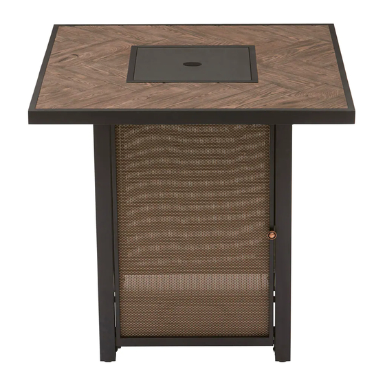
BAR TABLE
MODEL #FG-BKV32CHFP
ATTACH YOUR RECEIPT HERE
Español p. 18
Serial Number
Purchase Date
Questions, problems, missing parts? Before returning to your retailer, call our customer service
department at 1-866-439-9800, 8 a.m. - 8 p.m., EST, Monday - Friday.
AB17730
1
Advertisement
Chapters
Table of Contents

Summary of Contents for Allen + Roth FG-BKV32CHFP
- Page 1 • sophisticated • inspiring ANS Z21.97/CSA 2.41-2014 Outdoor Decorative Gas Appliances ITEM #0871274 allen + roth is a registered trademark ® of LF, LLC. All Rights Reserved. BAR TABLE MODEL #FG-BKV32CHFP ATTACH YOUR RECEIPT HERE Español p. 18 Serial Number...
-
Page 2: Table Of Contents
TABLE OF CONTENTS SAFETY INFORMATION ........................ PACKAGE CONTENTS ........................HARDWARE CONTENTS ....................... PREPARATION ..........................ASSEMBLY INSTRUCTIONS ......................OPERATING INSTRUCTIONS ...................... CARE AND MAINTENANCE ......................14 TROUBLESHOOTING ........................15 WARRANTY...........................16 REPLACEMENT PARTS LIST ......................SAFETY INFORMATION Please read and understand this entire manual before attempting to assemble, operate or install the product. - Page 3 SAFETY INFORMATION The installation must conform with local codes or, in the absence of local codes, with the National Fuel Gas Code, ANSI Z223.1 NFPA 54; National Fuel Gas Code; Natural Gas and ● Propane Installation Code, CSA B149.1; or Propane Storage and Handling Code, CSA B149.2, as applicable.
-
Page 4: Specifications
SAFETY INFORMATION Never leave a fire unattended. The appliance is hot during and after use. Always allow ample cooling time before touching or moving. SAFETY INFORMATION ABOUT PROPANE (LP) GAS The LP-gas supply cylinder to be used must be constructed and marked in accordance with the U.S. -
Page 5: Package Contents
PACKAGE CONTENTS PART DESCRIPTION QUANTITY PART DESCRIPTION QUANTITY Gas cylinder support Table top assembly Foot glider Door Weather cover Left panel Back panel Door handle Right panel Front-right leg Lava rocks (6.6 lb.-bag) Front-left leg Back-left leg Back-right leg Upper beam Bottom beam... -
Page 6: Hardware Contents
HARDWARE CONTENTS M6 x 15 mm M6 Washer Hex screwdriver M4 x 25 mm Bolt Bolt Qty. 30 Qty. 30 Qty. 1 Qty. 1 PREPARATION Before beginning assembly of product, make sure all parts are present. Compare parts with package contents list and hardware contents list. -
Page 7: Assembly Instructions
ASSEMBLY INSTRUCTIONS Attach left panel (C) to front-left leg (G) and back-left leg (H) with bolts (AA) and washers (BB) using hex screwdriver (CC). NOTE: Do not tighten bolts completely until assembly is complete. Hardware Used M6 x 15 mm Bolt M6 Washer Hex screwdriver Attach back panel (D) to back-left leg (H) and... - Page 8 ASSEMBLY INSTRUCTIONS Attach gas cylinder support (L) to left panel (C) and right panel (E) with bolts (AA) and washers (BB) using hex screwdriver (CC). NOTE: Do not tighten bolts completely until assembly is complete. Hardware Used M6 x 15 mm Bolt M6 Washer Hex screwdriver Attach upper beam (J) and bottom beam (K) to...
- Page 9 ASSEMBLY INSTRUCTIONS Attach door handle (O) with bolt (DD), then use Phillips screwdriver (not included) to screw tightly. Hardware Used M4 x 25 mm Bolt Place table top assembly (A) on a non-abrasive flat surface to prevent scratching. Attach base assembly to table top assembly (A) with bolts (AA) and washers (BB) using hex screwdriver (CC).
- Page 10 ASSEMBLY INSTRUCTIONS Place the lid (P) onto the fire bowl when not in use to protect it from the elements or when fire pit is cooled COMPLETELY after use. NOTE: Allow 30 minutes after use for fire pit to cooldown before placing the lid to prevent scalding.
-
Page 11: Operating Instructions
OPERATING INSTRUCTIONS GAS CYLINDER INSTALLATIONS Open the door (B) and place the gas cylinder (not included) into gas cylinder support (L). Connect the regulator. Screw the black handle clockwise to tighten, turn the black handle counterclockwise to remove. The hose must black handle point down. - Page 12 OPERATING INSTRUCTIONS CHECKING FOR LEAKS 1. Make 2 - 3 oz. of leak solution by mixing one part liquid dishwashing detergent and three parts water. 2. Apply several drops of solution where the cylinder attaches to the regulator and inspect the solution at the connection looking for bubbles.
- Page 13 OPERATING INSTRUCTIONS BATTERY INSTALLATION Make sure the control knob is in the “OFF” position. Unscrew the push button cap on the ignitor module located on the control panel to access the battery compartment. The ignitor module requires one AAA size battery. BATTERY IS NOT INCLUDED. CAUTION Please observe proper polarity and use the correct battery type when placing or replacing the battery.
-
Page 14: Operating Instruction
OPERATING INSTRUCTION CHECKING FOR FLAMES Observe flame height when lit. The burner will display blue and yellow flames. These flames should be a blue/yellow color between 1 - 2 in. height. These flames should not be yellow or produce thick smoke. -
Page 15: Troubleshooting
TROUBLESHOOTING PROBLEM POSSIBLE CAUSE CORRECTIVE ACTION 1. Wait until gas cylinder warms up 1. The gas cylinder is frosted over. and becomes unfrosted. 2. The openings are blocked. 2. Clear the blockage. 3. The control knob is not in the “ON” The burner will not 3. -
Page 16: Warranty
WARRANTY Firepits Burner, steel fire pit bowl, all mechanical parts and fittings to control panel and burner assembly, and all fire pit tops that are not cast aluminum are warranted for a period of one (1) year from original date of purchase, against defects in material and or workmanship. Rust is not covered. -
Page 17: Replacement Parts List
REPLACEMENT PARTS LIST For replacement, call our customer service department at 1-866-439-9800, 8 a.m. - 8 p.m., EST, Monday - Friday. PART DESCRIPTION PART # PART DESCRIPTION PART # Table top assembly NV-TTA Gas cylinder support NV-GCS Door NV-D Foot glider NV-FG Left panel NV-LP... - Page 18 welcoming • sophisticated • inspiring ANS Z21.97/CSA 2.41-2014 ¿Preguntas, problemas, piezas faltantes? Antes de volver a la tienda, llame a nuestro 66-439-9800 de lunes a viernes de 8 a.m. a 8pm., hora estándar del Este.
- Page 19 ÍNDICE INFORMACIÓN DE SEGURIDAD ....................20 CONTENIDO DEL PAQUETE ......................22 ADITAMENTOS ..........................23 PREPARACIÓN..........................23 INSTRUCCIONES DE ENSAMBLAJE ....................24 INSTRUCCIONES DE FUNCIONAMIENTO ...................29 CUIDADO Y MANTENIMIENTO......................31 SOLUCIÓN DE PROBLEMAS......................32 GARANTÍA............................33 LISTA DE PIEZAS DE REPUESTO....................34 INFORMACIÓN DE SEGURIDAD Lea y comprenda por completo este manual antes de intentar ensamblar, usar o instalar el producto.
-
Page 20: Información De Seguridad
INFORMACIÓN DE SEGURIDAD La instalación debe cumplir con los códigos locales o, de no haberlos, con el Código Nacional de Gas, ANSI Z223.1●NFPA 54; el Código Nacional de Gas; el Código lde Instalación de Gas Natural y Propano, CSA B149.1; o el Código de Manipulación y Almacenamiento de Propano, CSA B149.2, según corresponda. - Page 21 INFORMACIÓN DE SEGURIDAD INFORMACIÓN DE SEGURIDAD SOBRE EL GAS PROPANO (PL) FUELS USED IN LIQUEFIED PROPANE GAS WARNING: APPLIANCES, AND THE PRODUCTS OF COMBUSTION OF SUCH FUELS, CAN EXPOSE YOU TO CHEMICALS INCLUDING BENZENE, WHICH IS KNOWN TO THE STATE OF CALIFORNIA TO CAUSE CANCER AND CAUSE BIRTH DEFECTS OR OTHER REPRODUCTIVE HARM.
-
Page 22: Contenido Del Paquete
CONTENIDO DEL PAQUETE Pieza Descripción Cantidad Pieza Descripción Cantidad Soporte del cilindro de gas Tapa... -
Page 23: Aditamentos
ADITAMENTOS Perno M6 x 15 mm Arandela M6 Destornillador hexagonal Perno M4 x 25 mm Cant. 30 Cant. 1 Cant. 30 Cant.1 PREPARACIÓN Antes de comenzar a ensamblar el producto, asegúrese de tener todas las piezas. Compare las piezas con la lista del contenido del paquete y la lista del contenido de aditamentos. No intente ensamblar el producto si falta alguna pieza o si estas están dañadas. -
Page 24: Instrucciones De Ensamblaje
INSTRUCCIONES DE ENSAMBLAJE Fije el panel izquierdo (C) a la pata izquierda frontal (G) y a la pata izquierda posterior (H) con pernos (AA) y arandelas NOTA: no apriete los pernos por completo hasta finalizar el ensamblaje. Aditamentos utilizados Perno M6 x 15 mm Arandela M6 Destornillador hexagonal... - Page 25 INSTRUCCIONES DE ENSAMBLAJE Fije el soporte del cilindro de gas (L) al panel izquierdo (C) y al panel derecho (E) con pernos (AA) y arandelas (BB) usando el BB AA destornillador hexagonal (CC). NOTA: no apriete los pernos por completo hasta finalizar el ensamblaje.
- Page 26 Asegúrese de que el panel de control esté orientado hacia la puerta (B). panel de control caja de piloto ADVERTENCIA pueden tragar.
- Page 27 INSTRUCCIONES DE ENSAMBLAJE Cubra el fogón con la cubierta para la intemperie (N) cuando no esté en uso para protegerlo de los factores climáticos o cuando se haya enfriado POR COMPLETO después de haberlo usado.
-
Page 28: Instrucciones De Funcionamiento
INSTRUCCIONES DE FUNCIONAMIENTO INSTALACIÓN DEL CILINDRO DE GAS Abra la puerta (B) y coloque el cilindro de gas (no seincluye) en el soporte del cilindro de gas (L). Conecte el regulador. Gire la manija negra en dirección de las manecillas del reloj para apretarla;... - Page 29 INSTRUCCIONES DE FUNCIONAMIENTO BÚSQUEDA DE FUGAS 1. Prepare entre 59,14 ml y 88,72 ml de solución para detección de fugas mezclando una parte de detergente líquido para platos con tres partes de agua. 2. Aplique varias gotas de solución donde el cilindro se fija al regulador y revise si se forman burbujas en el área de las conexiones.
- Page 30 INSTRUCCIONES DE FUNCIONAMIENTO INSTALACIÓN DE LAS BATERÍAS Asegúrese de que la perilla de control esté en la posición "OFF" (apagado). Desatornille la tapa del botón en el módulo del encendedor que se encuentra en el panel de control para acceder al compartimiento de las baterías.
-
Page 31: Cuidado Y Mantenimiento
INSTRUCCIONES DE FUNCIONAMIENTO VERIFICACIÓN DE LLAMAS Observe la altura de las llamas. El quemador producirá llamas azules y amarillas. Estas llamas deben ser de color azul con amarillo y deben medir entre 2,54 cm y 5,08 cm de altura. Las llamas no deben ser amarillas ni deben producir humo espeso. -
Page 32: Solución De Problemas
SOLUCIÓN DE PROBLEMAS PROBLEMA CAUSA POSIBLE ACCIÓN CORRECTIVA 1. Espere a que el cilindro de gas se 1.El cilindro de gas está cubierto de caliente y se derrita la escarcha. escarcha. 2. Despeje la obstrucción. 2.Las aberturas están bloqueadas. 3. Gire la perilla de control a la posición 3.La perilla de control no está... -
Page 33: Garantía
GARANTÍA Fogones El quemador, la fuente del fogón de acero, todas las piezas mecánicas y los conectores al panel de control y al ensamble del quemador y todas las cubiertas del fogón que no son de aluminio fundido están garantizadas durante un (1) año a partir de la fecha original de compra, contra defectos en el material o la mano de obra.La garantía no cubre el óxido. -
Page 34: Lista De Piezas De Repuesto
LISTA DE PIEZAS DE REPUESTO Para obtener piezas de repuesto, llame a nuestro Departamento de Servicio al Cliente al ESCRIPTION PART # 1-866-439-9800 de lunes a viernes de 8 a.m. a 8pm., hora estándar del Este. PIEZA DESCRIPCIÓN PIEZA # PIEZA DESCRIPCIÓN PIEZA #...
Need help?
Do you have a question about the FG-BKV32CHFP and is the answer not in the manual?
Questions and answers
My burner stops working after about 5 minutes and you have to hold the button in to keep it lit. What can I do to fix the problem?
If the Allen + Roth FG-BKV32CHFP burner stops after 5 minutes and requires the button to be held in to stay lit, possible causes and solutions include:
1. Low gas pressure or empty cylinder: Replace the gas cylinder or ensure it is more than 1/4 full.
2. Blockage in burner or ports: Clear any blockage in the burner ports or lava rocks.
3. Improper lava rock placement: Remove excess lava rocks to ensure they only cover the upper surface of the burner.
4. Thermocouple issue: Though not directly mentioned, this symptom may suggest a thermocouple fault, which may require inspection or replacement.
Ensure the control knob is in the “ON” position and follow ignition instructions properly.
This answer is automatically generated