Table of Contents
Advertisement
Advertisement
Table of Contents

Related Manuals for hager domovea TJA450


Summary of Contents for hager domovea TJA450
- Page 1 domovea server TJA450...
- Page 2 domovea server Installer manual...
-
Page 3: Table Of Contents
Table of contents System presentation ............Introduction . -
Page 4: System Presentation
1. System presentation 1.1 Introduction The goal of domovea is to enlarge the possibilities of Tebis by bringing control and visualisation functions. Connected to the home data network, domovea interfaces with different types of IP devices such as cameras, door phones and display devices. In addition domovea provides with a large set of logical functions grouped in a sequence manager. -
Page 5: System Requirements
1.3 Required configuration The server domovea TJA450 shall be installed in the electrical panel. The Client and the Configuration tool softwares can be installed on any device with operating systems such as Microsoft Windows XP, WIndows VISTA and Windows 7. -
Page 6: Network Connexions
1.4.2 Network connexions Installation behind a DHCP Server The TJA4X0 is connected to a DHCP server (router or any other device having a DHCP function). In this case, the server TJA450 automatically waits for an IP address coming from the DHCP (Dyna- mic Host Configuration Protocol) server. -
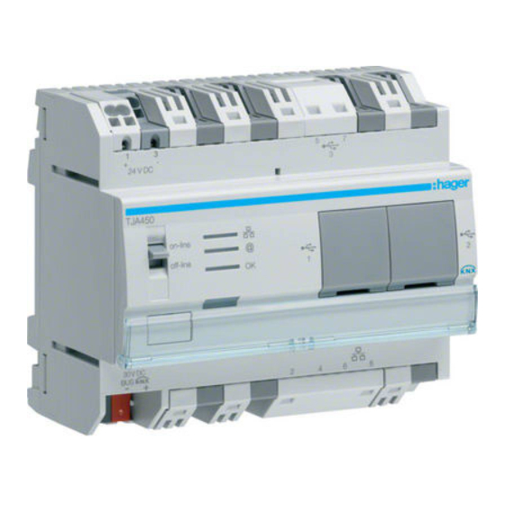
Page 7: Tja4X0 Front Panel
Connection to desired portal successful Red flickering Power supply problem Check power supply 30V DC Fixed Red Defective product Contact Hager Support Department Green flickering Domovea Server starting Fixed Green Domovea Server running The switch has two different positions: Online: - The server is set to DHCP configuration (default factory setting): at connection, the server is put in standby for 40s, expecting an IP address from a DHCP server. -
Page 8: Installation Of Client Software
1.5 Installation of client software Installing the client software and configuration tool is possible on computer terminals running on operating systems Windows XP , Windows Vista and Windows 7, 32 or 64 bits. • For installing software, insert the USB stick provided with the TJA450 server in a USB port of the target terminal. -
Page 9: Connection Without Dhcp Server
1.6.2 Connection without DHCP server • Change the IP address on the computer terminal to put it on the same network (steps through 7): Once, both devices are on the same net, you can work normally and proceed with next step. •... -
Page 10: Configuration Tool Description
2. Configuration tool description 2.1 General menu Server selection: this function is used to select the server. The selection is done automatically when launching the configuration tool but it is possible to select another one from here. Server settings: this function is used to set the servers settings. KNX interface: to configure the KNX connection. - Page 11 Electronic mail and contacts: to configure the email address of and its address book. Email configuration Sender email: to enter the email address used for sending emails. Outgoing mail server (SMTP): to enter the smtp server address used for sending emails. Examples: - smtp.live.fr for 'hotmail' addresses - smtp.gmail.com for 'gmail' addresses...
- Page 12 Calendar City name: to find the name of the city where the server is located in the list. Use the Search button to find the city. Longitude, Latitude: enter server city longitude and latitude data if the city is not in the list. OK: to validate Cancel: to cancel the data entry domovea server Information: to display the server occupation rate, the error log file and to reset the...
-
Page 13: Configuration Menu
management: Allows to manage the domovea projects' configuration files. Such files have Data .ddb format and their location is set by the user at the time of backup. ª Restore: allows restoring a configuration previously saved on the domovea server or on a user dened disk location. ª... -
Page 14: Start Up Guide For The Configuration Tool
3. Start up guide for the Configuration tool This section shows how to create a simple domovea project by treating an example. 3.1 Define the structure of the building 3 floors with different rooms on each: ground floor (garage, office). First floor (bedroom, kitchen and sitting room. -
Page 15: Create Groups
3.1.1 Create Groups A group is a part of the installation: a room, a floor of a building, a zone or a group of devices or a mix. The definition at group level is very important as it will be the one seen on each client (maximum number of groups is 100). -
Page 16: Knx Linking
If return to Groups, you will see the light inside the office: We proceed same way for the other devices (shutters, dimmers etc.) and the result is the following: 3.2 KNX Linking This chapter describes the procedure to link the created devices with the objects of the KNX project created by TX100 or ETS. - Page 17 • Select Devices on the menu (1), click on See KNX data (2) and choose Configured by TX100 (3). • Click Import (4) then select the txh file of TX100 programming (5). • The installation (inputs or outputs or both) appears on the screen. •...
- Page 18 Option 1: Associating TX100 output with an existing device In TX100 installation, Output No.1 is the On/Off light in the kitchen. To link this output with the • On/Off kitchen light, do a right click with the mouse on Output No. 1 in the right-hand window. Kee- ping mouse button depressed, drag-and-drop output (1) onto kitchen Light device, then confirm your selection (2).
- Page 19 To display the group addresses, click on the + button in the right section of the KNX Addresses window. The group addresses linked with the selected device are displayed in the left window (4). The group addresses linked with TX100 project output/input are displayed in the right-hand window (5).
-
Page 20: Ets Project
3.2.2 ETS project To step in this procedure, the ETS project and the devices in domovea have to be created. • To generate the ETS .xml file, select device view (1) and select the devices to be exported (2). • To export data, select File in the menu (1) then Save as CSV/XML in submenu (2), then select Export(3) and the XML format (4) in the popup displayed. - Page 21 • Select Devices on the menu (1), click on See KNX data (2) and choose Configured by ETS (3). • Import the .xml file of the ETS programming (4). • The data of ETS addresses will appear on the right hand side of the screen. •...
- Page 22 Exporting ETS in .esf format: • To generate the .esf file: open your project in ETS, select File in the menu (1), then Save as CSV/XML in the sub menu (2), then select Export in the window to Export to OPC server (3). Select the destination directory, name the file and confirm the operation by clicking on Save (4).
-
Page 23: Cameras
3.3 Cameras This chapter describes the procedure to link a network camera with the installation (maximum number of cameras is 10). 3.3.1 Camera selection The following list shows the guaranteed compatible cameras: Axis 207 series Mobotix 209 FD 209 MFD 2100 212 PTZ 213 PTZ... -
Page 24: Defining A Link To A Camera
3.3.2 Defining a link to a camera • Click Cameras button, then Add, and select the camera in the list. Enter the camera IP address to connect it to the installation. Important Note: The camera must be authorized in the network and its ports must be open. IP Address of the camera Port used by the camera Tick if authentication... -
Page 25: Display Profiles
3.4 Display profiles This section shows how to create profiles to personalize the aspect and the access rights of the different clients in the installation. Profiles are related to a physical displays like touch panels, PC etc. (maximum number of profiles is 30). Example 1: in a family residence, the little son should have access to his room but not to other rooms. - Page 26 * Custom sorting: Select Custom sorting for parameter 'Use the following sorting for devices and groups'. An additional tab named Custom sorting (1) will be displayed: Icons can be arranged by selecting your group of devices in the tree structure (2), then clicking on the device to be moved (3).
- Page 27 • On Configuration sheet, in Password protection (5), it’s possible to disable the access to certain areas by password. Prompt for password to indicate the password used to access On client startup, On settings access and When navigating outside default group. •...
-
Page 28: Icons And Backgrounds
3.5 Icons and backgrounds This section shows how to personalize the clients display, personal pictures may be imported. These pictures can than be used as icons or as backgrounds. The actions that can be done with resources are: : to create new resource, : to remove a resource, : to apply the parameters defined,... -
Page 29: Automation Sequences
3.6 Automation sequences A sequence is a collection of actions on devices, cameras, bus events etc (maximum number of sequences is 50). These actions can be organised and combined with conditions: logics, timers etc. The launch of a sequence may be manual (icon on a client) but may also be a trigger built with schedulers, bus events or device events. -
Page 30: Example 1: Going Out Sequence (Define Devices Status + Time Delayed Actions)
3.6.1 Example 1: going out sequence (define devices status + time delayed actions) This example shows how to create a very simple sequence based on a usual home situation: leave home for a couple of hours (all shutters down, all lights off, as some light to reach the exit is needed, once the sequence is started, the shutters go down, the lights go off but the office light is on for 1 minute to let you reach the door. -
Page 31: Example 2: Image Capture Of Entrance Door Automatism (Condition + Snapshot + Notification)
3.6.2 Example 2: Image capture of entrance door automatism (condition + snapshot + notification) This example shows how to get a snapshot of the main entrance if guest rings at the door bell. • Select Automatisms from menu (1) and click Add (2) then Adding a sequence (3) to create the se- quence. - Page 32 (1) Variable: to define the variable displayed in the notification. (1) Constant: to define the constant displayed in the notification. Hager S.A.S. - 132 bd d’Europe - B.P. 78 - 67 212 Obernai cedex (FRANCE) - Tél. +333 88 49 50 50 - www.hagergroup.net...