
Related Manuals for irinox CP One


Summary of Contents for irinox CP One
- Page 1 M A I N T E N A N C E I N S T R U C T I O N S REV No. REVISION DESCRIPTION REV. DATE PROOF READER FIRST EMISSION 26/10/2015 L.B. ADDED GAS R452A 10/09/2017 D.N.
- Page 2 We would like to remind you that the perfect operation of the machine also depends on its correct use. Keep this manual close to the CP ONE so that it can be consulted easily by you and anyone else. The graphic representations of the controls in the manual have been designed to make the machine easy and intuitive to use.
- Page 3 SAFETY INFORMATION The responsibility of the operations Below are the main general Safety performed on the machine, ignoring Standards: the indications stated in this manual, is imple- do not touch the machine with humid or wet • mented by the user. hands or feet do not work on the machine with bare feet •...
-
Page 4: Table Of Contents
INDEX 1. GENERAL DOCUMENTATION 1.1 GENERAL WARNINGS 1.2 INTRODUCTION 1.3 TRANSPORT AND HANDLING 1.4 UNPACKING AND DISPOSAL OF PACKAGING 2. INSTALLATION 2.1 PLATE DATA 2.2 POSITIONING 2.3 DIMENSIONAL DATA 2.4 ENVIRONMENTAL TEMPERATURES AND AIR EXCHANGE 2.5 COOLING CAPACITIES 2.6 ELECTRICAL CONNECTION 2.7 REFRIGERATOR CONNECTION 2.8 CONDENSATE DRAIN 2.9 WATER COOLING UNITS CONNECTION... -
Page 5: General Documentation
I to IV containing group 2 fluids. all connections and issue a declaration of perfect execu- tion that is in compliance with the provisions of the above- mentioned Directive. The joints made by IRINOX S.p.a. are in compliance with Standard EN14276-2. 1.3 TRANSPORT AND HANDLING •... - Page 6 1.4. UNPACKING • Remove the cardboard or wooden packaging or crate f r o m t h e w o o d e n b a s e o n w h i c h t h e m a c h i n e i s rested.
-
Page 7: Installation
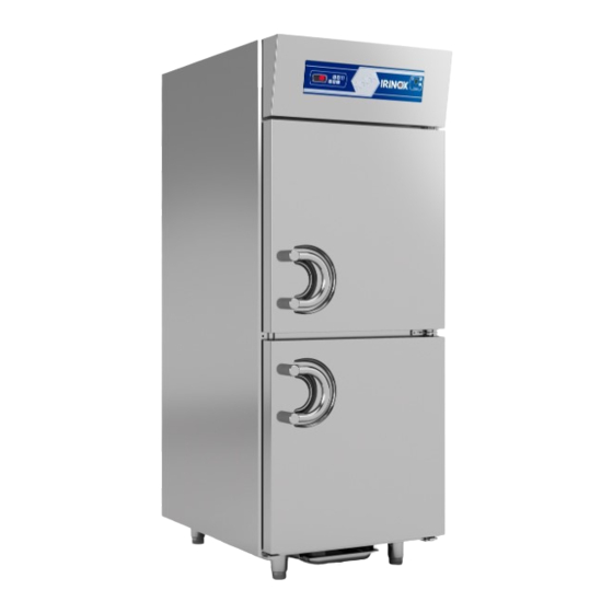
2. INSTALLATION 2.1. PLATE DATA • Check that the plate data and the characteristics of the electrical line correspond (V, kW, Hz, no. phases and power available). 31010 • The plate showing the appliance's characteristics is CORBANESE (TV) ITALY affixed on the right side of the holding cabinet (fig.2) Model Mod. -
Page 8: Dimensional Data
2.3. DIMENSIONAL DATA Service Area SECTION 871,5 SECTION... -
Page 9: Environmental Temperatures And Air Exchange
2.4. ENVIRONMENTAL TEMPERATURES AND AIR EXCHANGE For air-cooled chiller units, the temperature of the Table 2 operating environment must not exceed 30°C. The MINIMUM AIR EXCHANGE performance declared is not guaranteed above this temperature. The remote condensing units must be installed in oppo- site rooms or outdoors, in a place protected from direct Table 3 sunlight. -
Page 10: Refrigerator Connection
2.7. REFRIGERATOR CONNECTION 2.7.1. Equal level installation General criteria that must be satisfied in the installation of the remote units: Slope of the pipes (Fig.8) Fastening brackets onto the insulated pipes. The number of brackets to be applied to the refrige- rator connection line of the remote units Table 6. -
Page 11: Condensate Drain
Ø mm 19 mm Pipes maximum length: 15 m 2.8. CONDENSATE DRAIN CP ONE has a basin for collecting the condensate. The basin can be extracted from the bottom part of the cabinet holder. 2.9. WATER COOLING UNITS CONNECTION • During testing (mains water), with the machine at a standstill and water network ready, check that the condenser drain pipe does not allow water to escape. -
Page 12: Notes For The Installer
2.10. NOTES FOR THE INSTALLER Verification of correct installation and testing: • Check for any gas leaks from the seals or joints made during the installation phase. • Check the good insulation of the connection pipes between cabinet holder and remote condensing unit (when foreseen). -
Page 13: R404A /R452A Gas Safety Sheet
2.12. R404A / R452A GAS SAFETY SHEET Contact with the skin • Identification of dangers Sprays of liquid and the nebulised liquid can cause High exposure to inhalation can have anaesthetic cold burns. effects. Very high exposure can cause anomalies of the It is improbable that it is dangerous due to cutaneous heart beat and cause sudden death. -
Page 14: Disposing Of The Machine
2.13 DISPOSING OF THE MACHINE The machine must be demolished and disposed of in INFORMATION FOR THE USERS compliance with the Standards in force in the country of On implementation of the 2002/95/EC and installation, especially regarding the compressor 2002/96/EC Directives, relative to the coolant gas and lubricant oil. -
Page 15: Operation
3. OPERATION 3.1. USE The CP ONE cabinet holder is designed for preserva- tion of food products. CP ONE can work at +15 / -25°C. Especially: • POSITIVE mode (3°C), suitable for the preservation of fresh products, or for brief periods, of cooked food;... -
Page 16: Description And Operation
DATE AND TIME ADJUSTMENT Phase Description Press P4 for 1 second Use P4 or P6 to select “rtc” on the display Press P5 to confirm and access the clock setting menu. The indicator flashes Use P4 or P6 to select the current year (last 2 digits e.g. 2011 = 11) Press P5 to confirm and move on to the following setting. - Page 17 Common functions Function Description Operating mode Put the cabinet holder in Stand-by by pressing P3 selection. Press P5 for 4 seconds The display shows the set operating mode. Use P4 and P6 to set the desired operating mode where: POS = POSITIVE mode NEG = NEGATIVE mode CIOC = CHOCOLATE mode Press P5...
- Page 18 Signals Meaning Indicator Steady Flashing Change temperature set point Compressor command Compressor run requested but pending safety time end Defrosting in progress but pending Defrosting in progress compressor safety time end Evaporating fan command During evaporating fan stop time Light inside cell manually switched on Internal cell light switched on for door opening by pressing P1 Liquid line solenoid valve command...
-
Page 19: Stop Modes
3.4. STOP MODES In case of emergency, to switch off the cabinet holder, press P3 for 2 seconds and disconnect power Fig. 20 supply. ATTENTION! Press P3 with machine running to place the cabinet holder in Stand-by: all the commands are removed from the various components;... -
Page 20: Routine Maintenance
4. MAINTENANCE 4.1. ROUTINE MAINTENANCE: The information and the instructions in this chapter are intended for all staff operating the machine: the user, the maintenance technician and the unskilled staff. Elementary Safety Standards To carry out routine cleaning and maintenance safely, follow the safety regulations of ( Fig.23) : •... -
Page 21: Troubleshooting
4.3. TROUBLESHOOTING The machines' electronic control is supplied with a sound and visual signal system which signals the presence of an alarm; press a key to silence the sound alarm. Diagnostics managed by the electronics: Meaning Display Minimum temperature (HACCP alarm) Maximum temperature (HACCP alarm) Open door (HACCP alarm) No voltage (HACCP alarm) - Page 22 Diagnostics NOT managed by the electronics: MALFUNCTION POSSIBLE CAUSE POSSIBLE SOLUTION No power supply Check the connection to the electrical line The cell front board does not switch on Protective fuses triggered Fuse replacement by an authorised technician No power supply Check the connection to the electrical line Technician intervention to replace Faulty fan...
-
Page 23: Extraordinary Maintenance
4.4. EXTRAORDINARY MAINTENANCE The information and instructions in this paragraph are Fig. 28 destined exclusively to the specialised staff authorised to intervene on the electrical and refrigerator compo- nents of the machine. 4.4.1. How to access the electronic boards and the electrical control panels. - Page 24 IRINOX headquarter via Madonna di Loreto, 6/B 31020 Corbanese di Tarzo (TV) - Italy production site via Caduti nei lager, 1 Z.I. Prealpi Trevigiane, loc. Scomigo 31015 Conegliano (TV) - Italy P. +39 0438 2020 F. +39 0438 2023 irinox@irinox.com...
Need help?
Do you have a question about the CP One and is the answer not in the manual?
Questions and answers