
Related Manuals for THERMEx THW20

Summary of Contents for THERMEx THW20
- Page 1 Heat Pump Manual Thermex Solutions PRODUCT MANUAL HEAT PUMPS Document 001-D135 11 May 2015 Models THW20 THW40 THW60 THW80 THW100 THW150 THWW20 THWW40 THWW50 THWW60 THWW80 THWW100 THWP20 THWP40 THWP60...
- Page 2 For any service work not carried out by Thermex Solutions, Thermex Solutions will only cover costs of refrigerant to the value of the specified charge in the units. · It is not Thermex Solutions’s responsibility to connect the heat pump to the BMS unless agreed to before delivery of the heat pump ·...
-
Page 3: Table Of Contents
This manual is designed to explain the installation, operation and the basic maintenance of the product. It is recommended that for service issues Thermex Pty Ltd be contacted before and work commences. A comprehensive service manual is available to be down loaded from the website. -
Page 4: Safety
Heat Pump Manual SAFETY THE UNIT IS DESIGNED FOR OUTDOOR USE. WARNING The unit is only to be installed, operated, maintained and serviced by qualified persons only. Operation of units such as these can be hazardous and should be serviced by persons with the proper training and qualifications. - Page 5 Heat Pump Manual SAFETY First Aid Eye Contact. Immediately flush with tepid water or sterile saline solution. Hold eyelids apart for 15 minutes while irrigating. Seek medical attention. Inhalation. Remove from area of exposure immediately and if you are assisting a victim avoid being exposed.
-
Page 6: Marking
A four digit serial number sticker will also be placed under the marking plate. With this number Thermex can trace the date of manufacture of the product and details on the unit. The wiring diagram will show the model of the unit and the options installed. -
Page 7: Warranty
Thermex Pty Ltd for consideration. This warranty is given by Thermex Pty Ltd, ABN 13 245 994 351, of 161 Orchard Rd, Chester Hill, NSW 2162 – Ph 02 9721 9310. -
Page 8: Water Circuit
Heat Pump Manual HOT WATER CIRCUIT The hot water circuit consists of 1. Condenser heat exchanger – this may be a plate heat exchanger, a coaxial heat exchanger or shell and tube 2. Flow switch or flow meter 3. Copper pipe work The heat pump will run whenever called unless the controller detects a drop in flow. -
Page 9: Technical Data
TECHNICAL DATA AIR TO WATER HEAT PUMPS All units have a details data sheet available – the information supplied below is intended as a guide only – please contact Thermex for a copy of the individual model data sheets Model THW07 Nominal heating capacity –... - Page 10 Heat Pump Manual TECHNICAL DATA AIR TO WATER HEAT PUMPS Model THW20 and THWDW20 Nominal heating capacity – Rated duty point – in red 20°C Ambient conditions 45°C Water supply 60% RH 45°C 50°C 55°C 60°C 65°C 70°C Water Supply Temperature 18.62...
- Page 11 Heat Pump Manual TECHNICAL DATA AIR TO WATER HEAT PUMPS THW50 and THWDW50 THW50H* and THWDW50H Model Nominal heating capacity – kW Rated duty point – in red 20°C Ambient conditions 45°C Water supply 60% RH 45°C 50°C 55°C 60°C 65°C 70°C Water Supply Temperature...
- Page 12 Heat Pump Manual TECHNICAL DATA AIR TO WATER HEAT PUMPS THW100H and THW100 and THWDW100 Model THWDW100H Nominal heating capacity – kW Duty point in red 20°C Ambient conditions 45°C Water supply 60% RH 45°C 50°C 55°C 60°C 65°C 70°C Water Supply Temperature 85.00 83.80...
- Page 13 Heat Pump Manual TECHNICAL DATA Electrical Data – All units Model Maximum A/ Phase Maximum continuous Locked rotor amps - current per compressor 13.1 19.4 10kW 15.7 22.0 20kW 17.5 24.5 30kW 27.1 38.0 40kW 33.6 47.0 50kW 38.0 49.0 60kW 51.2 76.0...
- Page 14 Heat Pump Manual TECHNICAL DATA PERFORMANCE DATA Performance Chart at 40/45°C Water Return/ Supply 50°C Condensing temperature – 20°C/ 15°C evaporator water THWW100 THWW150 THWW200 THWW250 Model Nominal heating capacity – Heating Cooling Side Heating Cooling Side Heating Cooling Side Heating Cooling Side Capacity...
-
Page 15: Heating System Schematic
Heat Pump Manual HEATING SYSTEM SCHEMATIC THW20, THW40 and THW60 THW80 and THW120 Heating System Schematic Symbols Air Cooled Pressure Liquid receiver Evaporator transducer Pump One way valve Ball valve Compressor TX valve Flow meter Pressure Sight glass Drier gauge... -
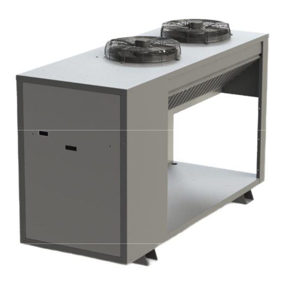
Page 16: Dimensions
Heat Pump Manual DIMENSIONS .dxf and .dwg files are available for all models – please contact Thermex for details THW07 THW20... - Page 17 Heat Pump Manual DIMENSIONS THW30 and THW40 THW50 and THW60...
- Page 18 Heat Pump Manual DIMENSIONS THW80 THW100 AND THW130...
- Page 19 Heat Pump Manual DIMENSIONS THWW20 to THWW40 Water to Water THWW50, THWW60 and THWW80 Water to Water...
-
Page 20: Transport And Storage
It is the consignee’s responsibility to make any subsequent claims upon the carrier or respective insurance company. Any hidden damage should be reported to Thermex as soon as possible. If the unit is to be stored before installation then care must be taken to ensure no foreign matter can get into the water pipes. - Page 21 This should be filled out by someone experienced in heat pump installation and returned to Thermex if there are any doubts about the installation. It is essential to ensure that adequate and safe service access to the heat pump is provided.
- Page 22 Heat Pump Manual INSTALLATION Temperature Sensing Water temperature probes The unit will be supplied with a 20 meter water temperature probe. The heat pump will be supplied with a 20m temperature probe that is designed to measure the temperature in the central storage tanks and this is a part of the installation process. If this temperature probe is not installed properly the water temperature in the tank may not reach the set point.
- Page 23 Heat Pump Manual INSTALLATION If the pressure is below this then there may be a leak in the refrigeration circuit and water may be drawn into the refrigeration circuit on start up. If the pressure is below this then it is recommended that the heat pump be inspected by a qualified refrigeration mechanic before filling the system with water.
- Page 24 Heat Pump Manual INSTALLATION Electrical Installation The heat pump draws a large amount of current and it is important that the connection of the unit to the power supply must be carried out in accordance with the local standards and only by a licensed electrician.
- Page 25 The heat pump has programming to allow it to be connected to the internet for monitoring or to be monitored via high level SNMP interface. Thermex can install customer IP address prior to the unit being dispatched otherwise see the service section of this document for instructions on changing the system settings.
- Page 26 If the unit is to communicate to the high level BMS using BACnet or Modbus then it will be supplied with an XML mapping file with the relevant OID points. The installed firmware must be version U302_56_EB04_200 or higher. The Thermex heat pump unit runs the following Building Management System interface firmware: ·...
- Page 27 Heat Pump Manual INSTALLATION The SNMP, BACnet IP and Modbus TCP interfaces provide full control, monitoring and configuration of the Pump and Transfer Unit via the mapped data points. All of the interfaces are IP based and share a single 10/100Base-T thernet physical layer which is also shared with the local HTTP web server.
- Page 28 Heat Pump Manual INSTALLATION Multiple Heat pump Installations Aqua Coolers heat pump can be installed in multiple installations for redundancy or to allow scaling – up to 8 heat pumps can be installed together. If the master heat pump loses power, develops a fault or the control wire between the heat pumps is interrupted then all other heat pumps will keep operating on their internal temperature controls.
-
Page 29: Operation
Heat Pump Manual INSTALLATION If one of the heat pumps loses power then the heat pumps further along the daisy chain will go off line. If one of the heat pumps in the daisy chain develops a fault then the other ones further along will continue to run. - Page 30 Heat Pump Manual OPERATION Using the key pad controller All the setting can be viewed and all the operational parameters can be set from the controller inside the electrical box using the key pad on the front of the controller. There are four buttons –...
-
Page 31: Control
Heat Pump Manual OPERATION The maximum operational water temperature is 60°C – the water temperature setting should not be set above this. The unit can be constructed to operate at up to 70°C but this MUST be specified at the time of order. Operating a standard unit above 60°C will void the warranty on the compressor. - Page 32 Heat Pump Manual CONTROL Water Flow Control The system has a flow switch that monitors the flow. If the flow is interrupted for any reason the controller shuts the unit down. After the unit has reached temperature the pump will continue to run for 30 seconds – this is to flush the condenser once it has cooled down If the flow is interrupted the unit will shut down.
- Page 33 Heat Pump Manual CONTROL On a water to water unit the controller is monitoring the evaporator water. There is an evaporator water set point and if the evaporator water drops below this then the controller will open the solenoid valve to prevent freezing of the evaporator. This is typically set at 5C High Pressure Protection This setting will open the hot gas valve if this pressure is breached –...
-
Page 34: Service And Maintenance
A comprehensive preventative maintenance program is available through Thermex carried out by qualified refrigeration mechanics. Should any faults be identified then please call Thermex to arrange a service call. Recommended preventative maintenance program Operation... - Page 35 Water temperatures – both the storage tank temperature and the temperature in the heat pump’s condenser · On the THW20, THW40 and THW60 units it is monitoring the suction and discharge pressures of the system. On the HP80 and HP100 the suction pressures are monitored and the discharge temperatures are monitored ·...
- Page 36 If new firmware has been released, it can be uploaded to the controller with a USB key. Presumably Thermex will email the firmware – this has to be loaded onto the USB – ensure that the firmware is the only .HEX file in the route directory. Put the USB key into the USB slot on the rear of the controller.
- Page 37 Heat Pump Manual SERVICE and MAINTENANCE If the firmware has been upgraded then the webpage will need to be upgraded. The file that needs to be uploaded is a .BIN file. It will be emailed with the new .HEX file for the board. Open a browser with http://10.1.1.130:8076/mpfsupload OR if the controller has already been...
- Page 38 Heat Pump Manual SERVICE and MAINTENANCE Maximum and Minimum Temperature Limits · This minimum Scroll to the PARAMETERS MENU then to the SET POINTS sub maximum temperature limit for menu · Scroll to “MIN TEMP LIMIT” or “MAX TEMP LIMIT” the heat pump and is there to prevent casual operators setting ·...
- Page 39 THEY ARE NOT altered without a full understanding of the heat pumps programming or without checking with Thermex first. The settings reflect Thermex recommended setting for the installation ordered. If at a later time another heat pump is installed in tandem or the heat pump is added to a multiple heat pump set them some of the setting may change.
- Page 40 Heat Pump Manual SERVICE and MAINTENANCE Controller Input and Output Schematic Connector Type Control Outputs – 1 to 8 across 24VDC 1 Compressor enable 2 Hot Gas defrost – circuit 1 the top of the board 3 Compressor 2 enable 4 Hot gas defrost enable –...
- Page 41 Heat Pump Manual WIRING DIAGRAM This diagram shows the basic wiring between the master and slave units. If any of the slaves has a fault then it will report back to the master that is has a fault but the master will not shut the system down.
-
Page 42: Wiring
WIRING DIAGRAM An electrical box control circuit wiring diagram unique to the heat pump will be in the electrical box with this manual – if it has not been provided please contact Thermex to organise a copy. Legend for component marking in the electrical box/ wiring diagram... -
Page 43: Trouble Shooting
Heat Pump Manual TROUBLE SHOOTING In the event the heat pump develops a fault then the fault is displayed on the screen readout on the control board. The faults displayed are comprehensive but not fully descriptive. - Page 44 Heat Pump Manual TROUBLE SHOOTING The wiring diagram above shows a typical wiring layout for the units. The way the systems logic works is that on the control circuit all the components in the line need to be closed before the compressor contactor can be energised and the compressor can start. In the case shown above there is –...
- Page 45 Heat Pump Manual TROUBLE SHOOTING On all units, circuit 1 – or CCT1 on the controller – is on the left hand side of the unit. Other faults that are shown on the controller are FLOW FAULT/ PUMP FAIL The flow switch has open detecting a problem with the water flow. Some possible faults are ·...
-
Page 46: Release Notes
Heat Pump Manual RELEASE NOTES – SOFTWARE Date Issue Description 20/02/13 U302_56_EB4_205 15/12/13 Firmware upgrade to version U302_64_EB4_206 02/12/14 Software to version U302_64_EB4_211 · Introduced flow meter option for high temperature units · Added output for 2 fan bank for 100 and 150kW models 01/01/15 Software to version U302_64_EB4_212... - Page 47 02/12/14 Pressure testing of heat exchanges to 10bar introduced as part of testing procedure Notes about swimming pool models added Sheet metal re-designed – THW10, THW20, THW30, THW40, THW50, THW60, THW80 Design of 100Kw and 150Kw units finalised 01/01/15 All swimming pool models re-designed with wider and angles drip...
-
Page 48: Commissioning
Heat Pump Manual COMMISSIONING It is important that the heat pump is commissioned in accordance with the guidelines below in order to ensure proper and trouble free operation. Outlined below is a check list showing all the considerations that must be taken for the proper installation and operation of the heat pump Pre-start checks Procedure... - Page 49 Heat Pump Manual COMMISSIONING Water Connection Was the pressure on the suction gauge checked before the unit was filled with water – see Installation Open the mains make up water to the heat pump – has all the air been bled from the system Check the water path for leaks Start Up Press the ON/OFF button on the front of the heat pump and the pump will start up...
- Page 50 Heat Pump Manual COMMISSIONING Tandem Installation Checks On the master heat pump set the cycle time to “10 minute test” and after 10 minutes check that the heat pumps duty cycle. Fault the running heat pump and check the other heat pump starts and vis-a-versa Finishing Off Is the electrical box closed and...
-
Page 51: Site Inspection
Heat Pump Manual SITE INSPECTION Proposed Date Inspected: Heat pump Model: Inspected By: Company: Contact Number: Business Name Of Installation Site: Installation Site Street Address: Installation Site Phone Number: Installation Site Facsimile Number: Installation Site Contact Name: Installation Site Contact Position: Access Limitations: Any issues relating to... - Page 52 Heat Pump Manual SITE INSPECTION Heat pump Installation – Clearances Mark out any condensing units or other possible heat sources that may effect the operation of the proposed heat pump installation Highlight any walls/fixtures/items that encroach on the clearances required for the heat pump installation. Insert Drawing and photo of site here: Minimum Space Requirements: Heat pump Model...
- Page 53 Heat Pump Manual SITE INSPECTION Heat pump Water Circuit Requirements Notes: Pipe Size: Pipe Insulation: Length: Height Difference: Balancing Valve: YES/NO Isolation Valves: YES/NO Water YES/NO Make Up Water: YES/NO Treatment: Treatment Used: Supply Pressure: Flow Rate: Pressure Tap YES/NO In Line Filtration: YES/NO Points:...
- Page 54 General Notes/Feedback Completion Thermex uses the information from this site inspection sheet to confirm that the heat pump will be installed and operating correctly. Should any problems or issues be raised as a result of the site inspection process then Thermex will take steps to address them with the customer, ensuring that the heat pump operates reliably and without compromise to the long service life we expect of our products.
- Page 55 Heat Pump Manual HEAT RECOVERY COIL – 20kW INSTALLATION The heat recovery coil must be installed on a firm level surface The heat recovery coil must be given adequate ventilation to allow proper air flow around the unit All power cable should be installed through the cable glands and tightened to ensure adequate protection against the weather and prevent damage to the cables Ensure the covers on the junction box are re-installed properly to ensure weather ingress integrity...
- Page 56 Heat Pump Manual INSTALLATION - HEAT RECOVERY COIL – 20kW There is a heat rejection relay also in the junction box marked on the wiring diagram as “HR”. Again 240V power will need to be connected to terminals 7 and 8 as marked on the wiring diagram.
- Page 57 Heat Pump Manual TECHNICAL DATA – 20kW HEAT RECOVERY COIL TECHNICAL DATA – FAN COIL UNIT Model HP20W3 ELECTRICAL DATA Power Supply 415V 3 Phase – 50 Hz Full Load Amps A/ Ph Fans 2 x 450mm Air flow Vertical discharge Fan wiring Star Water connections...
- Page 58 Heat Pump Manual WIRING DIAGRAM – 20kW HEAT RECOVERY COIL...
Need help?
Do you have a question about the THW20 and is the answer not in the manual?
Questions and answers