
Subscribe to Our Youtube Channel
Related Manuals for BeiJer GN-9289

Summary of Contents for BeiJer GN-9289
- Page 1 Modbus TCP/UDP network adapter GN-9289 User manual Page 1 of (70) G-series GN-9289 Modbus TCP_UDP Rev. 1.01.docx...
- Page 2 GN-9289 User Manual DOCUMENT CHANGE SUMMARY REV. PAGES REMARKS DATE Editor 1.00 New Document 2018/7/30 1.01 First release 2019/01/29 Page 2 of (70) G-series GN-9289 Modbus TCP_UDP Rev. 1.01.docx...
-
Page 3: Table Of Contents
1.1. Safety Instruction ............................7 1.1.1 Symbols ............................... 7 1.1.2 Safety Notes ............................7 2. Specification ..............................8 2.1.1 GN-9289 (MODBUS TCP) ......................... 8 2.2. General Specification ............................9 2.2.1 General Specification .......................... 9 2.2.2 Interface Specification ........................10 2.3. GN-9289 LED Indicator ..........................11 2.3.1... - Page 4 Expansion Slot Information Special Register (0x2000, 8192) ............48 8.4. Supported MODBUS Function Codes ......................50 9. Object models ............................... 51 9.1. Supported Objects ............................51 9.2. Identity Object ............................... 52 9.2.1. Common Services ..........................52 Page 4 of (70) G-series GN-9289 Modbus TCP_UDP Rev. 1.01.docx...
- Page 5 9.10 Expansion Slot Object ..........................63 9.10.1 Common Services ..........................63 9.10.2 Class Attributes ..........................63 9.10.3 Instance Attributes ..........................63 Trouble Shooting ..........................66 10.1. How to diagnose by LED indicator ......................66 Page 5 of (70) G-series GN-9289 Modbus TCP_UDP Rev. 1.01.docx...
-
Page 6: Important Notes
Do not permit any vibration approaching it directly. • Go through module specification carefully, ensure inputs, output connections are made with the specifications. Use standard cables for wiring. • Use Product under pollution degree 2 environment. Page 6 of (70) G-series GN-9289 Modbus TCP_UDP Rev. 1.01.docx... -
Page 7: Safety Instruction
The modules are equipped with electronic components that may be destroyed by electrostatic discharge. When handling the modules, ensure that the environment (persons, workplace and packing) is well grounded. Avoid touching conductive components, G-BUS Pin. Page 7 of (70) G-series GN-9289 Modbus TCP_UDP Rev. 1.01.docx... -
Page 8: Specification
Signal Description Signal Description Pin No. System Power, 24V System Power, Ground System Power, 24V System Power, Ground Field Power, Ground Field Power, Ground Field Power, 24V Field Power, 24V Page 8 of (70) G-series GN-9289 Modbus TCP_UDP Rev. 1.01.docx... -
Page 9: General Specification
Refer to ‘Adapter TCP/IP Special Register (0x1040, 4160)’ at section ‘ 3.3.3’ ** When using in ‘60℃ ~ 70℃’ temperature environment, the power dissipation is limited to 0.8A. Page 9 of (70) G-series GN-9289 Modbus TCP_UDP Rev. 1.01.docx... -
Page 10: Interface Specification
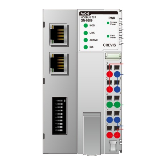
1 Green, Field Power Status 2 LEDs (each RJ45 Connector) 1 Yellow, Link/Active 1 Green, Not used Module Location Starter module left side of G-Series system Field Power Detection About 14Vdc Page 10 of (70) G-series GN-9289 Modbus TCP_UDP Rev. 1.01.docx... -
Page 11: Gn-9289 Led Indicator
- Memory error or CPU watchdog error. 2.3.2. Physical Connection LED(LINK) Status To indicate Not Powered or Not Linked Device may not be powered Adapter physical connected Green Adapter Ethernet Controller physically connected Page 11 of (70) G-series GN-9289 Modbus TCP_UDP Rev. 1.01.docx... -
Page 12: Exchange Data/Traffic Present Led(Active)
2.3.5 Field Power Status LED Status To indicate No field, System power Not supplied 24Vdc field power, 5Vdc system power. Supplied Green Supplied 24Vdc field power, 5Vdc system power. field, System power Page 12 of (70) G-series GN-9289 Modbus TCP_UDP Rev. 1.01.docx... -
Page 13: Dimension
GN-9289 User Manual 3. Dimension 3.1 GN-9289 (mm) Page 13 of (70) G-series GN-9289 Modbus TCP_UDP Rev. 1.01.docx... -
Page 14: Mechanical Set Up
4.1 Total Expansion The number of the module assembly that can be connected is 63 so the maximum length is 426mm Exception GN-9289 is excepted to calculate maximum length because that is double width module. 4.2. Plugging and Removal of the Components. -
Page 15: Module Mounting
GN-9289 User Manual 4.3 Module mounting Page 15 of (70) G-series GN-9289 Modbus TCP_UDP Rev. 1.01.docx... -
Page 16: How To Supply The Power Correctly
System and Field power must be supplied separately as the picture above. ※ If the power is supplied to each System and Field power from same power source, it would be vulnerable to power noise. Page 16 of (70) G-series GN-9289 Modbus TCP_UDP Rev. 1.01.docx... -
Page 17: Convenience Function
GN-9289 User Manual 5. Convenience Function 5.1. Web Server Network Adapter Page 17 of (70) G-series GN-9289 Modbus TCP_UDP Rev. 1.01.docx... - Page 18 GN-9289 User Manual Expansion Module Page 18 of (70) G-series GN-9289 Modbus TCP_UDP Rev. 1.01.docx...
-
Page 19: Iap Functionality
After setting up the dip switch as 254 or 255, Power off and on in order to start the IAP mode. (254=Fixed IP Address (192.168.0.100) / 255=Last used IP Address) After Login the Web Browser connecting (User ID: beijer, Password: beijer) To update the binary file. Page 19 of (70) G-series GN-9289 Modbus TCP_UDP Rev. 1.01.docx... - Page 20 GN-9289 User Manual Has been updated. Please reboot the adapter. Page 20 of (70) G-series GN-9289 Modbus TCP_UDP Rev. 1.01.docx...
-
Page 21: Gn-9289 Communication Interface
IP_DIP bit#7 = ON : Enable DHCP/BOOTP * = ON : Use Lowest IP Address with IP_DIP value * DHCP/BOOTP have to be set in special register (0x1045) (default : BOOTP). Page 21 of (70) G-series GN-9289 Modbus TCP_UDP Rev. 1.01.docx... -
Page 22: Rs232 Port For Modbus/Rtu, Touch Panel Or Ioguide
GN-9289 User Manual 6.3 RS232 Port for MODBUS/RTU, Touch Panel or IOGuide Pin# Signal Name Description Reserved ---- RS232 TXD RS232 RXD RS232 GND Page 22 of (70) G-series GN-9289 Modbus TCP_UDP Rev. 1.01.docx... -
Page 23: Modbus/Tcp Ip - Address Setup
20 times every 2sec. If BOOTP/DHCP sever does not response, the Adapter applies its IP Address with EEPROM (Latest saved IP Address). The following is an example of adapter IP-Address setup that can be used with a third party BOOTP/DHCP server. * Beijer BOOTP server Page 23 of (70) G-series GN-9289 Modbus TCP_UDP Rev. 1.01.docx... -
Page 24: Ip-Address Setup Using Dip Switch (Manual Function)
These are examples of adapter IP-Address setup by manual function. Ex) XXX. XXX. XXX. 1 Ex) XXX. XXX. XXX. 2 Ex) XXX. XXX. XXX. 8 Ex) XXX. XXX. XXX. 253 Page 24 of (70) G-series GN-9289 Modbus TCP_UDP Rev. 1.01.docx... - Page 25 If the adapter is Bootp/DHCP enabled (Dip Pole #9 ON), adapter will send Bootp/DHCP request 20 times every 2sec, after power reset. If Bootp/DHCP server does not response, adapter will use the latest saved IO address in EEPROM. Page 25 of (70) G-series GN-9289 Modbus TCP_UDP Rev. 1.01.docx...
- Page 26 Double click on one of the detected ‘Bootp request message’ and set the IP address. If you wait for more the 40 seconds, you have to restart the GN-9289. Another way to set are, “Add New Device”Click on “Add New Device”, write the Mac Address and then the IP Adress.
- Page 27 GN-9289 User Manual Check IP address of the normal. Page 27 of (70) G-series GN-9289 Modbus TCP_UDP Rev. 1.01.docx...
-
Page 28: I/O Process Image Map
The data exchange between network adapter and expansion modules is done via an I/O process image data by G-Series protocol. The following figure shows the data flow of process image between network adapter and expansion modules. Page 28 of (70) G-series GN-9289 Modbus TCP_UDP Rev. 1.01.docx... -
Page 29: Modbus Interface Register/Bit Map
* 16. Process output image bits All output registers area are addressable by bit address. 0x1000~ Read/Write 1,5,15 Size of output image bit is size of output image register * 16. Page 29 of (70) G-series GN-9289 Modbus TCP_UDP Rev. 1.01.docx... -
Page 30: Example Of Input Process Image (Input Register) Map
Discrete Input 8 pts (Slot#6) Discrete Input 8 pts (Slot#5) 0x0008 Discrete Input 8 pts (Slot#8) Discrete Input 8 pts (Slot#7) 0x0009 Discrete Input 8 pts (Slot#9) Discrete Input 8 pts (Slot#8) Page 30 of (70) G-series GN-9289 Modbus TCP_UDP Rev. 1.01.docx... -
Page 31: Example Of Output Process Image (Output Register) Map
Analog Output Ch3 low byte (Slot#8) 0x080B Discrete Output low 8 pts (Slot#10) Empty, Don't Care Discrete Out 4 pts (Slot#9) 0x080C Empty, Don't Care Discrete Output high 8 pts (Slot#10) Page 31 of (70) G-series GN-9289 Modbus TCP_UDP Rev. 1.01.docx... -
Page 32: Modbus Tcp/ Udp Interface
≥ 3.5 char ≥ 3.5 char 1 char 1 char Up to 252 chars 2 chars Function and data field of MODBUS/TCP are identical to function and data field of MODBUS/RTU. Page 32 of (70) G-series GN-9289 Modbus TCP_UDP Rev. 1.01.docx... -
Page 33: Modbus Tcp/ Udp Mbap Header
• Length - The length field is a byte count of the following fields, including the Unit Identifier and data fields. • Unit Identifier – This field is used for intra-system routing purpose. Typically MODBUS server must be returned with the same value set by MODBUS client. Page 33 of (70) G-series GN-9289 Modbus TCP_UDP Rev. 1.01.docx... -
Page 34: Supported Modbus Function Codes
Quantity of Outputs Lo 0x0A Response Field name Example Function Code 0x01 Byte Count 0x02 Output Status 0x55 Output Status 0x02 In case of address 0x1015~0x1000 output bit value: 10101010_01010101. Page 34 of (70) G-series GN-9289 Modbus TCP_UDP Rev. 1.01.docx... -
Page 35: 0X02) Read Discrete Inputs
Quantity of Inputs Lo 0x0A Response Field name Example Function Code 0x02 Byte Count 0x02 Input Status 0x80 Input Status 0x00 - In case of address 0x0015~0x0000 input bit value: 00000000_10000000. Page 35 of (70) G-series GN-9289 Modbus TCP_UDP Rev. 1.01.docx... -
Page 36: 0X03) Read Holding Registers
Byte Count 0x04 Output Register#0 Hi 0x11 Output Register#0 Lo 0x22 Output Register#1 Hi 0x33 Output Register#1 Lo 0x44 - In case of address 0x0800, 0x0801 output register value: 0x1122, 0x3344. Page 36 of (70) G-series GN-9289 Modbus TCP_UDP Rev. 1.01.docx... -
Page 37: 0X04) Read Input Registers
Field name Example Function Code 0x05 Output Address Hi 0x10 Output Address Lo 0x01 Output Value Hi 0xFF Output Value Lo 0x00 - Output bit of address 0x1001 turns ON. Page 37 of (70) G-series GN-9289 Modbus TCP_UDP Rev. 1.01.docx... -
Page 38: 0X06) Write Single Register
0x06 Register Address Hi 0x08 Register Address Lo 0x00 Register Value Hi 0x11 Register Value Lo 0x22 - In case of address 0x0800 output register value: 0x0000 changes to 0x1122. Page 38 of (70) G-series GN-9289 Modbus TCP_UDP Rev. 1.01.docx... -
Page 39: 0X08) Diagnostics
Echo Request Data Reset with Factory default 1),2) IP Address, Subnet Mask Address, Gateway Address will be the factory defaults value. 2) Mac Address will be the factory default value. Page 39 of (70) G-series GN-9289 Modbus TCP_UDP Rev. 1.01.docx... - Page 40 (neither a normal response nor an exception response), since its last restart, clear counters operation, or power–up. Sub- Data Field (Request) Data Field (Response) Description function 0x000F(15) 0x0000 Slave No Response Count Page 40 of (70) G-series GN-9289 Modbus TCP_UDP Rev. 1.01.docx...
-
Page 41: 0X0F) Write Multiple Coils
0x0F Starting Address Hi 0x10 Starting Address Lo 0x00 Quantity of Outputs Hi 0x00 Quantity of Outputs Lo 0x0A In case of address 0x1015~0x1000 output bit value: 00000000_00000000changes to 00000001_01010101. Page 41 of (70) G-series GN-9289 Modbus TCP_UDP Rev. 1.01.docx... -
Page 42: 0X10) Write Multiple Registers
Starting Address Lo 0x08 Quantity of Registers Hi 0x00 Quantity of Registers Lo 0x02 .- In case of address 0x0800, 0x0801 output register value: 0x0000, 0x0000 changes to 0x1122, 0x3344. Page 42 of (70) G-series GN-9289 Modbus TCP_UDP Rev. 1.01.docx... -
Page 43: 0X17) Read/Write Multiple Registers
Read Reg. Value#0 Lo 0x22 Read Reg. Value#1 Hi 0x33 Read Reg. Value#1 Lo 0x44 In case of address 0x0800, 0x0801 output register value: 0x0000, 0x0000 changes to 0x1122, 0x3344. Page 43 of (70) G-series GN-9289 Modbus TCP_UDP Rev. 1.01.docx... -
Page 44: Error Response
Gateway Path Unavailable path from the input port to the output port for processing the request. - GN-9289 response exception code 01, 02, 03, 04 and 06. Page 44 of (70) G-series GN-9289 Modbus TCP_UDP Rev. 1.01.docx... -
Page 45: Modbus Special Register Map
- 1word 0x1002(4098), Product code - 1word 0x1003(4099), Firmware revision - 2word 0x1004(4100), Product serial number - String Type consists of valid string length (first 1word) and array of characters Page 45 of (70) G-series GN-9289 Modbus TCP_UDP Rev. 1.01.docx... -
Page 46: Adapter Watchdog Time, Other Time Special Register (0X1020, 4128)
Read/Write 2word Gateway. If 192.168.123.254,then 0xA8C0, 0xFE7B. Ethernet physical address (MAC-ID). 0x1053(4179) Read 3word If 11-22-33-44-55-66, then 0x2211, 0x4433, 0x6655. * Power off and then power on, this value is applied. Page 46 of (70) G-series GN-9289 Modbus TCP_UDP Rev. 1.01.docx... -
Page 47: Adapter Information Special Register (0X1100, 4352)
DHCP/Booth enable, Dip SW(0x01), Field Power On = 0x8101 upto Expansion slot’s GT-number including GN 0x110E(4366) Read 33word First 1word is adapter’s number, if GN-9289, then 0x9289 0x1110(4368) Read 1word Number of expansion slot upto Expansion slot Module Id. -
Page 48: Expansion Slot Information Special Register (0X2000, 8192)
Slot#21 0x2280(8832)~0x229F(8863) Slot#22 0x22A0(8864)~0x22BF(8895) Slot#23 0x22C0(8896)~0x22DF(8927) Slot#24 0x22E0(8928)~0x22FF(8959) Slot#25 0x2300(8960)~0x231F(8991) Slot#26 0x2320(8992)~0x233F(9023) Slot#27 0x2340(9024)~0x235F(9055) Slot#28 0x2360(9056)~0x237F(9087) Slot#29 0x2380(9088)~0x239F(9119) Slot#30 0x23A0(9120)~0x23BF(9151) Slot#31 0x23C0(9152)~0x23DF(9183) Slot#32 0x23E0(9184)~0x23FF(9215) Slot#33 0x2400(9216)~0x241F(9247) Slot#34 0x2420(9248)~0x243F(9279) ….. Slot#63 0x27C0(10176)~0x27DF(10207) Page 48 of (70) G-series GN-9289 Modbus TCP_UDP Rev. 1.01.docx... - Page 49 0x201C(8220) 0x203C(8252) 0x205C(8284) 0x207C(8316) ……. 0x27DC(10204) + 0x1D(+29) 0x201D(8221) 0x203D(8253) 0x205D(8285) 0x207D(8317) ……. 0x27DD(10205) + 0x1E(+30) 0x201E(8222) 0x203E(8254) 0x205E(8286) 0x207E(8318) ……. 0x27DE(10206) + 0x1F(+31) 0x201F(8223) 0x203F(8255) 0x205F(8287) 0x207F(8319) ……. 0x27DF(10207) Page 49 of (70) G-series GN-9289 Modbus TCP_UDP Rev. 1.01.docx...
-
Page 50: Supported Modbus Function Codes
** Nothing of output, input, memory or configuration parameter corresponding slot returns Exception 02. 8.4. Supported MODBUS Function Codes MODBUS Reference Documents http://www.modbus.org MODBUS Tools http://www.modbustools.com, modbus poll http://www.win-tech.com, modscan32 Page 50 of (70) G-series GN-9289 Modbus TCP_UDP Rev. 1.01.docx... -
Page 51: Object Models
Class Code Name of Object Identity Required Message Router Required Assembly Required Connection Manager Required Port Required TCP/IP Interface Required Ethernet Link Required GBus Manager Vendor-specific Expansion Slot Vendor-specific 1~63 Page 51 of (70) G-series GN-9289 Modbus TCP_UDP Rev. 1.01.docx... -
Page 52: Identity Object
Instance Attribute Acces Name Data Type Value s Rule Revision UINT 0001 Max Instance UINT 0001 Maximum ID Number Class Attributes UINT 0000 Maximum ID Number UINT 0000 Instance Attributes Page 52 of (70) G-series GN-9289 Modbus TCP_UDP Rev. 1.01.docx... -
Page 53: Instance Attributes
Bit 2: Overflow I/O size Code Bit 3: I/O Configuration failure Bit 4: EEPROM Checksum fault Bit 6: Invalid Module ID Bit 7: Firmware fault Firmware UDINT YYYYMMDD Release Date Page 53 of (70) G-series GN-9289 Modbus TCP_UDP Rev. 1.01.docx... -
Page 54: Message Router Object
09 00 01 00 02 00 04 00 06 Object Class List Array of 00 F4 00 F5 00 F6 00 70 00 UINT 71 00 Number Available UINT Maximum number of connections supported Page 54 of (70) G-series GN-9289 Modbus TCP_UDP Rev. 1.01.docx... -
Page 55: Assembly Object
Input process image data BYTE Data Output (Consumed) Set/G Array Process Image Output process image data BYTE Data 9.5 Connection Manager Object Class Code: 06 9.5.1 Class Attributes, Instance Attribute None Page 55 of (70) G-series GN-9289 Modbus TCP_UDP Rev. 1.01.docx... -
Page 56: Port Object
Port Type UINT 0004 , TCP/IP Port 0002 , CIP port number Port Number UINT associate with port UINT Port Object Padde EPATH Port Name Short_String Padded Node Address EPATH Page 56 of (70) G-series GN-9289 Modbus TCP_UDP Rev. 1.01.docx... -
Page 57: Tcp/Ip Object
00 00 20 F6 24 01 Path PATH STRUCT of: IP address UDINT Network Mask UDINT Interface Gateway Address Get/Set UDINT Configuration Name Server UDINT Name Server 2 UDINT Domain Name STRING Page 57 of (70) G-series GN-9289 Modbus TCP_UDP Rev. 1.01.docx... -
Page 58: Status Instance Attributes
2 – The device shall use the interface configuration values via DHCP upon start-up. 3-15 – Reserved. If TRUE, the device shall resolve host names by querying a DNS server. Reserved 5-31 Page 58 of (70) G-series GN-9289 Modbus TCP_UDP Rev. 1.01.docx... -
Page 59: Ethernet Link Object
Service Name Code Class Instance 0x01 Get_Attribute_All 0x0E Get_Attribute_Single 9.8.2. Class Attributes Instance Attribute Access Name Data Type Value Rule Revision UINT 0002 Max Instance UINT 0001 Num Instances UINT 0001 Page 59 of (70) G-series GN-9289 Modbus TCP_UDP Rev. 1.01.docx... - Page 60 Bit 2~4 : Auto negotiation 5 : Manual Setting required Reset Bit 6 : Local Hardware Fault Others : 0 Physical ARRAY of 6 USINTs Same as MAC address Address Page 60 of (70) G-series GN-9289 Modbus TCP_UDP Rev. 1.01.docx...
-
Page 61: G-Bus Manager Object
Output Reset at stop BOOL 0: Disabled(default) 1: Enable *After the system is reset, the new “Set Value” action is applied. If slot location is changed, default value is set automatically. Page 61 of (70) G-series GN-9289 Modbus TCP_UDP Rev. 1.01.docx... - Page 62 Network Adapter Module External ID = 0x00 External ID for slot position #1 External ID for slot position #2 External ID for slot position #62 External ID for slot position #63 Page 62 of (70) G-series GN-9289 Modbus TCP_UDP Rev. 1.01.docx...
-
Page 63: Expansion Slot Object
4 Byte Firmware Revision Structure of USINT USINT *After the system is reset, the new “Set Value” action is applied. If slot location is changed, default value is set automatically. Page 63 of (70) G-series GN-9289 Modbus TCP_UDP Rev. 1.01.docx... - Page 64 - usually it is used by Analog I/O module. 1 1: Priority 3 (high) S (Status for Profibus Slot Diagnostic) 0: No Status 1: Support Word Input Diagnostic(0x8000 = -32678) Page 64 of (70) G-series GN-9289 Modbus TCP_UDP Rev. 1.01.docx...
- Page 65 1 1: have no Input or Output Data … 1 1 1 1 1 1: 63 Bit/Byte/Word MODBUS Reference MODBUS Reference Documents http://www.modbus.org MODBUS Tools http://www.modbustools.com, MODBUS poll http://www.win-tech.com , MODSCAN32 Page 65 of (70) G-series GN-9289 Modbus TCP_UDP Rev. 1.01.docx...
-
Page 66: Trouble Shooting
- Contact Sales team and send module for repair. - Check main power Cable System Power LED turns - System power is not supplied. - Contact Sales team and send module for repair. Page 66 of (70) G-series GN-9289 Modbus TCP_UDP Rev. 1.01.docx... - Page 67 8 Channels, 0~10, 0~5, 1~5Vdc, 12bits, 10RTB 3468 GT-3468 8 Channels, 0~10, 0~5, 1~5Vdc, 16bits, 10RTB GT-342F 16 Channels, 0~10, 0~5, 1~5Vdc, 12bits, 20P connector 342F GT-346F 16 Channels, 0~10, 0~5, 1~5Vdc, 16bits, 20P connector 346F Page 67 of (70) G-series GN-9289 Modbus TCP_UDP Rev. 1.01.docx...
- Page 68 Common for 0Vdc 7508 7511 GT-7511 Power Expansion, In 24Vdc, Out 1A/5Vdc 7518 GT-7518 Common for 24Vdc GT-7588 Common for 0Vdc, 24Vdc 7588 GT-7641 Field Power, 5/24/48 Vdc, 110/220 Vac 7641 Page 68 of (70) G-series GN-9289 Modbus TCP_UDP Rev. 1.01.docx...
- Page 69 - Sink : The method of in/output power supply if a device has no power source. - Source : The method of in/output power supply if a device has the power source. Page 69 of (70) G-series GN-9289 Modbus TCP_UDP Rev. 1.01.docx...
- Page 70 GN-9289 User Manual Head office Beijer Electronics AB Box 426 20124 Malmö, Sweden Phone +46 40 358600 www.beijerelectronics.com Page 70 of (70) G-series GN-9289 Modbus TCP_UDP Rev. 1.01.docx...
Need help?
Do you have a question about the GN-9289 and is the answer not in the manual?
Questions and answers