Table of Contents
Advertisement
Advertisement
Table of Contents

Related Manuals for Skipala DIGR-1502/E

Summary of Contents for Skipala DIGR-1502/E
- Page 1 USER MANUAL FOR DIGR-1502/E CONTROLLER Version: 1.3 October 2018...
-
Page 2: Table Of Contents
CONTENTS 1. Technical data........2. Description ........3. Connection ........4. Operating status ......... 11 5. Activation ........11 6. R-run / S-stop ........12 7. Setting and saving parameters ....12 8. Description of parameters ......12 9. Maintenance ........22 Disposal ........ -
Page 3: Technical Data
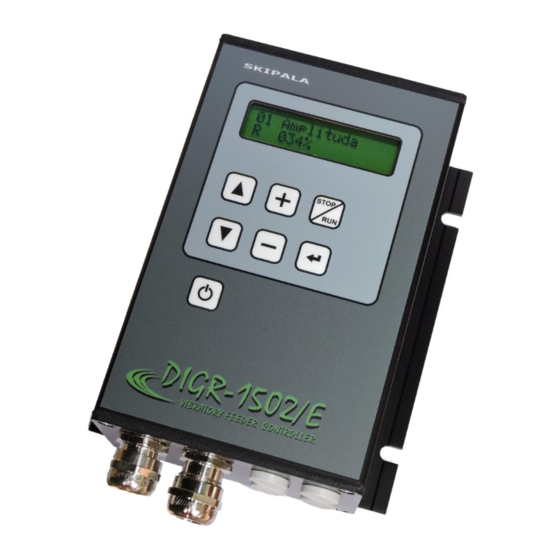
2000 m Dissipated power 10 W Weight 1.3 kg 2. Description The DIGR-1502/E controller is designed for control of vibration feeders driven with an electromagnetic coil. Two basic parameters, i.e. output voltage amplitude and frequency controlled. operation controller is defined with parameters that are set by... - Page 4 Fig. 1 – Description of controls Parameter Parameter number name Operational status Parameter Parameter value locked/unlocked Display - Increase 2 x 16 displayed value characters stop – ▲ - Browsing Switching over through parameters in S-stop or upward R-run condition ▼...
- Page 5 Fig. 2 – Basic dimensions 105,00 130,00 120,00 5/23...
- Page 6 Fig. 3 - Connection of controller external parts supply drive 6/23...
-
Page 7: Connection
3. Connection Connection external electric components controller may be carried out only by the person with adequate electro-technical qualification. Connection may be done only if the controller is disconnected from the mains. Caution! Electric charge remains capacitors after controller disconnection from mains. - Page 8 Fig. 4 – dismantling of the cap To allow better access to the terminal block, we recommend dismounting also part with outlets (Fig. 5). Fig. 5 – Removal of the part with outlets There connecting terminals under this (Fig. 6). 8/23...
- Page 9 Fig. 6 – Connecting terminals 3.3. Connection of the power section The controller is equipped with a 2P + PE terminated lead cable. Connect the plug to a standard 230V socket that is triggered by a circuit breaker with a maximum rated current of 16A characteristic B.
- Page 10 Caution! The protective wire should be at least by 15 mm longer than the other wires. Fig. 7 - Termination of power cables Fig. 8 – Connection of wires 3.4. Connection of the control section Wire cross section area 0.08 –...
-
Page 11: Operating Status
4. Operational condition Operational condition is shown on the display as the first symbol of the bottom line (Fig. 1). The controller can be in one of four statuses: The controller is energized, however, all activities are turned off. STOP - The controller is turned on and it is in the S-stop condition. -
Page 12: R-Run / S-Stop
component (contactor) from a master electric device. 6. R-run / S-stop The controller is ready for operation after turning It is either in the R-run or W-wait condition in dependence upon setting of functions of digital inputs (parameter A19, A21). The controller is switched over in stop the S-stop condition after depressing the button. - Page 13 the output storage tank of the feeder. We recommend setting parameters to 0 s. If the controller is in the W-wait status parts are taken from storage their movement causes a short interruption of the signal from the filling sensor. The Delay ON (parameter A12) must be longer than interruption signal.
- Page 14 Tip for you: The operators can correct the value within the permitted range without greatly affecting the correct work of the feeder. 8.7. A19 Input IN1 Determining the use of digital input IN1. Not used – The input is not used or is only monitored state transferred output...
- Page 15 both stock sensors are active for the time in parameter A13 activity stops. Ejector IN – The input controls the ejector together with digital output OUT1, OUT2 (Chapter 8.12.). 8.8. A20 Sensor 1 type Type of sensor connected to input IN1. Normal open (NO) - 24V is on the output of the sensor if the supplied part is present.
- Page 16 Tip for you: the feeder to be activated. this setting if you need to control the feeder from the master control system and digital inputs IN1, IN2 are occupied by the connected sensors. Stop – The input is configured as digital. The supply of the +24V signal causes the controller to stop.
- Page 17 Ejector E2 (Fig. 9b) – is similar to the ejector E1, except that uses three timers. Timer (parameter A25) suppresses short impulses at the input IN2. Timer T13 (parameter A27) determines the delay between the signal IN2 and switching output OUT. Timer T12 (parameter A26) determines the length of switching output OUT.
- Page 18 Monitor IN1 OFF – The output monitors the off status of digital input IN1. The setting and functions are the same as when monitoring input IN1 ON. Monitor IN2 ON – The output monitors the on status of digital input IN2. The setting and functions are the same as when monitoring input IN1 ON.
- Page 19 8.21. A34 Wave type It defines the course of output voltage. full wave half wave -equivalent of unidirectional rectification 8.22. A35 Unused parameter for this type of controller. 8.23. A36 Switch ON States how the controller behaves after connecting the supply voltage. Press button - After connecting the supply voltage, controller off.
- Page 20 Czech – Is delivered if another language version has not been ordered. As standard Russian or German can be ordered or another language agreed on. 8.27. A40 Information For more information about this product, visit our Internet pages http://www.skipala.cz 8.28. A41 Password Typing password temporarily...
- Page 21 29 Timer T21 00.0 s 30 Timer T22 00.0 s 31 Timer T23 000 s 34 Wave type full wave 36 Switch ON press button 37 Service fnc not used 38 Lock/unlock 39 Language english 40 Info www.skipala.cz 41 Password 21/23...
-
Page 22: Maintenance
9. Maintenance controller does require special maintenance. Carry out Pergorm only regular inspection accordance with ČSN EN50110-1 ed.3 Regulation No. 50/78 Sb. In the case of failure do not repair - send the controller to the manufacturer for repair. When changing the fuse, observe the prescribed T8A value. -
Page 23: Es Declaration Of Conformity
ES DECLARATION OF CONFORMITY In accordance with Act No. 90/2016 Coll. on conformity assessment of specified products when they are placed on the market, as amended. Manufacturer: Skipala s.r.o. Rybnik 162, 560 02 Rybnik Czech Republic Id. No.: 06607551 http://www.skipala.cz...
Need help?
Do you have a question about the DIGR-1502/E and is the answer not in the manual?
Questions and answers