
Related Manuals for Skipala DIGR-1202/E

Summary of Contents for Skipala DIGR-1202/E
- Page 1 Karel Skipala Automating manufacturing processes, modernising machine control, producing industrial electronics http://www.skipala.cz USER MANUAL FOR DIGR-1202/E CONTROLLER Version: 1.4 July 2015...
-
Page 2: Table Of Contents
CONTENTS 1. Technical data........2. Description ........3. Connection ........4. Operating status ......... 10 5. Activation ........10 6. R-run / S-stop ........10 7. Setting and saving parameters ....11 8. Description of parameters ......11 9. Maintenance ........21 Disposal ........ -
Page 3: Technical Data
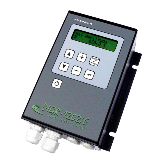
Interference suppression EN 55011/A Short-circuit resistance 1.5 kA Weight 1.2 kg 2. Description The DIGR-1202/E Controller is a triac controller for regulating vibration feeder driven by an electromagnetic coil. The basic regulation value is the output voltage. controller used quickly setting... - Page 4 S-stop or R-run enter ▼ - saving - browsing adjusted values in parameters DIGR-1202/E DIGR-1202/E downward VIBRATORY FEEDER CONTROLLER VIBRATORY FEEDER CONTROLLER activation or - decrease deactivation of the displayed the controller value...
- Page 5 Fig. 2 - basic dimensions 105,00 130,00 120,00 5/22...
- Page 6 Fig. 3 - connecting the external part of the controller 230V 50Hz supply drive A 6/22...
-
Page 7: Connection
3. Connection The external electric parts of the controller must only connected someone with proper electrotechnical qualification. Only connect controller is disconnected from the network 3.1. Assembly controller installed horizontally vertically with the outlets downwards. It must be mounted on a firm part of the equipment without direct vibrations. - Page 8 For easier access to the terminal box, we recommend dismantling parts with forged pieces (Fig. 5). Fig. 5 – dismantling parts with outlets The connecting terminals are under this cap (Fig. 6). Fig. 6 – connecting terminals 3.3. Connecting the power part The controller has an internal T8A circuit breaker, which protects the device against short circuits, not against...
- Page 9 Connect according to Fig. 3. If the cable to the coil longer than 1.5 m, recommend connecting with a shielded cable. The shielding is terminated by the metal outlet. Th termination of power cables is shown in Fig. 7. The cross-sections of conductors is as follows: Cross-section of conductors 0.5 - 1.5 mm Cable diameter...
-
Page 10: Operating Status
4. Operating status operating status displayed first character of the lower line (Fig. 1): The controller is under voltage, all activities are Attention! disconnected. The inside circuits of the controller are under voltage! STOP – The controller is connected in the S-stop status. -
Page 11: Setting And Saving Parameters
7. Setting and saving parameters The number of parameter is shown on the display, the first line on the left (Fig. 1) The initial letter A shows which set is displayed. ▼ ▲ buttons browse required parameter. If it is not locked (key symbol), the value of the parameter can be changed using the button. - Page 12 is filled. Individual parts pass around the sensor and create short impulses. The Timeout OFF (parameter A13) must be longer than these impulses. Then they will be ignored and the controller switches into the W-wait status after the actual filling of the magazine. The parameters can be set from 0-25 s.
- Page 13 status vice versa immediate, parameters A12, A13 do not affect this. Tip for you: Use this setting if the feeder is controlled from a master control system. Maximum reserve - The sensor is connected to the input monitoring maximum reserve storage tank being filled by the feeder.
- Page 14 8.10. A22 Type of sensor 2 Determining type sensor connected input IN2. The setting is identical as for input IN1 (Chapter 8.8.). 8.11. A23 Analogue AIN Determining the use of analogue input AIN. It can be configured as analogue 0-10V, or digital 0/24V. Connected - The input is not used.
- Page 15 Air – The output controls the air supply valve into feeder. valve switched before activation of the feeder. The time is set using parameter A25 (Timer T11). When the feeder is turned off, the air is turned off with a delay, which is set using parameter A26 (Timer T12).
- Page 16 Fig. 9b – activity of the ejector E2 Monitor IN1 ON – The output monitors the activated status digital input IN1. This only monitored when the drive is in the status RUN - operating. If during the period set by parameter A27 (Timer T13), there is signal 24V on input IN1, the output OUT switches on.
- Page 17 8.13. A25 Timer T11 Universal timer where the use is determined by setting parameter A24 (Output OUT1). 8.14. A26 Timer T12 Universal timer where the use is determined by setting parameter A24 (output OUT1). 8.15. A27 Timer T13 Universal timer where the use is determined by setting parameter A24 (Output OUT1).
- Page 18 8.23. A36 Activation States how the controller behaves after connecting the supply voltage. Using button After connecting supply voltage, the controller is off. It is activated by pressing the button Automatically - After connecting the supply voltage the controller is automatically activated. This setting does exclude...
- Page 19 8.28. A41 Information For more information about this product, visit our Internet pages http://www.skipala.cz 8.29. Factory settings If there are complications with controller, RESTART it to reset the factory settings of all parameters. RESTART as follows: ...
- Page 20 Fig. 10 - parameters table number factory values of values of of parameter values application application 11 Amplitude 34,00% 12 Timeout ON 00.0s 13 Timeout OFF 00.0s 14 Starting time 01.0s 15 Batch ON 00.0s 16 Batch OFF 00.0s 17 Ampl. MAX 100% 18 Ampl.
-
Page 21: Maintenance
9. Maintenance controller does require special maintenance. Carry out Pergorm only regular inspection accordance with ČSN 33 2000-1, ČSN 34 3100 Regulation No. 50/78 Sb. In the case of failure do not repair - send the controller to the manufacturer for repair. -
Page 22: Es Declaration Of Conformity
ES DECLARATION OF CONFORMITY accordance with No. 22/97 Coll. technical requirements products, effective amended by act. Manufacturer: Karel Skipala Rybník 162, 560 02 Česká Třebová Czech Republic Reg. No.: 48608017 http://www.skipala.cz Identification of the product: Name: Digital power controller Model:...
Need help?
Do you have a question about the DIGR-1202/E and is the answer not in the manual?
Questions and answers