
Subscribe to Our Youtube Channel
Related Manuals for Qualstar XLS-810160

Summary of Contents for Qualstar XLS-810160
- Page 1 ‘ XLS-810160 & XLS-810240 Tape Libraries Installation Manual Document No. 501801 Rev. 07-01-19...
- Page 2 Qualstar reserves the right to modify the design or specification without notice. This specification may not be construed as a contractual obligation except as specifically agreed to by Qualstar in writing at the time of order.
- Page 3 Qualstar products are covered by one or more of the following patents: 6,271,982; 6,560,061; and 7,181,313. Other patents pending. Qualstar equipment is manufactured from new parts, or new and used parts. In some cases, Qualstar equipment may not be new and may have been previously installed.
- Page 4 EMI line power filter Reduction of Hazardous Substances (RoHS) Qualstar is committed to the implementation of RoHS (Restriction of the use of certain hazardous substances in electrical and electronic equipment) in accordance with the European Directive. The compliance date is July 1, 2006, at which time Qualstar will certify that its tape library products are compliant with the RoHS standard.
-
Page 5: Table Of Contents
Table of Contents 1 About This Manual ........1-1 About the XLS . - Page 6 Removing the X-Axis Hard Stop ........6-7 Attaching the Expansion Pod to the XLS-810160/810240....6-8 Installing the Rear Side Panel .
- Page 7 Appendix A Library Addresses ......A-1 Addresses for the XLS-810160/810240 ......A-2 Addresses for Expansion Pod, I/O Ports, and Fixed Port Slots .
- Page 8 Table of Contents viii 501801 Rev. 07-01-19...
-
Page 9: About This Manual
About This Manual This manual is intended for anyone installing the Qualstar® XLS Library. It provides instructions for completing XLS installation and configuration. Important: Although Qualstar has made every effort to ensure the accuracy of the information contained in this manual, no guarantee is expressed or implied that the manual is error free. - Page 10 1.1 About the XLS • The XLS-85000 (also referred to as a MEM2) contains 517 cartridges. Figure 1-1 LRM with one MEM2 501801 Rev. 07-01-19...
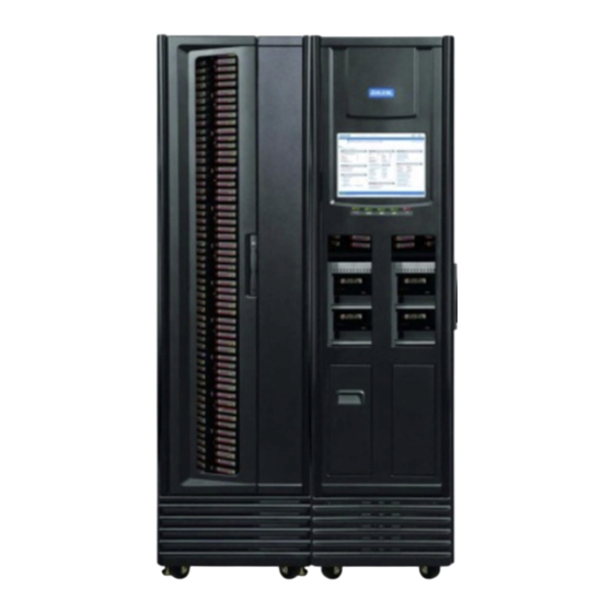
- Page 11 1-2, the XLS-810160/810240 accommodates up to 10 tape drives, up to 245 cartridges, and up to two, 10-slot I/O ports. As an option, one Media Expansion Modules (MEM) can be installed on the left side of the XLS-810160/810240. See Section 1.3 on page 1-16 for more information.
-
Page 12: Library Resource Module (Lrm)
1.2 Library Resource Module (LRM) Library Resource Module (LRM) Figure 1-3 shows the inside of the LRM, while Figure 1-4 on page 1-5 shows the back of the LRM. The LRM contains the following components and features: • PC bay, which includes the system controller (see Section 1.2.1 on page 1-5) •... - Page 13 About This Manual Drive bay Battery module (2 drives/bay) Power supplies (up to 3) Power connector PC bay Figure 1-4 Rear view of the LRM 1.2.1 PC Bay Figure 1-4 shows the location of the PC bay at the rear of the LRM. The PC bay houses the system controller and slides in and out of the LRM for servicing.
- Page 14 1.2 Library Resource Module (LRM) Power System Figure 1-5 shows the power components accessible from the rear of the LRM. An optional redundant power input module is also avaivable. Battery module Filler plate Power supplies (up to 3) Power switch/ breaker Power connector Figure 1-5 Power components...
- Page 15 About This Manual Cooling fans CAN bus controller Host Bus Adapter cards Hard drive HBA connectors EMI shield Serial & Ethernet connectors Figure 1-6 System controller components in the PC bay XLS Library Installation Manual...
- Page 16 1.2 Library Resource Module (LRM) 1.2.2 Touch Screen and LEDs Shown in Figure 1-7, each LRM includes a touch screen, used to display the X-Link Management Interface, and five LEDs. Figure 1-7 Touch screen and status LEDs (X-Link log-in screen displayed) Touch Screen The 15-inch LCD touch screen on the front of the LRM allows for local control and monitoring of library operations.
- Page 17 About This Manual Figure 1-8 X-link Home page (Logical Libraries View selected) LEDs The LEDs on the front panel indicate the library's operational status at a glance. Status LEDs are also included on the back of each tape drive assembly and each power supply. 1.2.3 Robotic Handler and Barcode Reader Shown in...
- Page 18 1.2 Library Resource Module (LRM) the carousel of an attached MEM. The handler is controlled by the medium changer interface and shared by all host software applications on a first-come, first-served basis. Figure 1-9 Robotic handler (shown reaching into an attached MEM) Gripper Assembly The gripper assembly is the part of the handler that actually picks and places the cartridges in the storage slots and tape drives.
- Page 19 Barcode labels must conform to the ANSI/AIM BCI-1995, Uniform Symbol Specification (USS-39). Detailed specifications for XLS barcodes and labels can be found in Qualstar Product Information Note 040, “XLS, RLS, and TLS Barcode Labels.” To obtain this document, go to www.qualstar.com...
- Page 20 1.2 Library Resource Module (LRM) 1.2.4 Tape Drives Tape Drive Assemblies Shown in Figure 1-11, an XLS tape drive assembly consists of an LTO tape drive enclosed in a drive carrier. Figure 1-11 Fibre Channel tape drive assembly (rear view) Two models of tape drives are available: SCSI tape drive assemblies include dual SCSI HD68 connectors and a single status LED, while Fibre Channel tape drive assemblies include a duplex LC multi-mode Fibre Channel receptacle and three LEDs.
- Page 21 About This Manual Drive Bays Figure 1-12 shows the view of several drive bays through the open door. Each drive bay can hold up to two tape drive assemblies, which are installed from the rear of the LRM. Figure 1-12 View of drive bays throughthe open door For safety reasons, all tape drive or drive filler assemblies (see Figure 1-13) must be...
- Page 22 1.2 Library Resource Module (LRM) 1.2.5 I/O Ports As shown in Figure 1-14, I/O ports on the front of the LRM allow cartridges to be imported or exported without opening the door(s) and interrupting XLS operations. Each I/O port holds 10 cartridges in a removable magazine. Depending on the model, the XLS can include one or two I/O ports.
- Page 23 Door and Light Curtain Sensors Door The XLS-810160 and XLS-810240 have a single door on the right side. The XLS-85000 MEM2 has a single door that opens on the front. All doors have windows for viewing robot operations and the LRM’s have front windows. There are also viewing windows on the side panels.
-
Page 24: Media Expansion Module (Mem)
Figure 1-16 the Media Expansion Module (MEM) includes a rotating motor-driven carousel containing cartridge slots. The XLS-85000 (MEM2) can store up to 517 cartridges. The XLS-810160/810240 can be expanded by adding one XLS-85000 MEM to its left side. Door Carousel... -
Page 25: How This Manual Is Organized
About This Manual How This Manual Is Organized Table 1-2 is a quick reference for locating the information in this manual. Refer to... For... Overview of the installation process, including a Chapter 2, “Preparing for Installation” check list of required and optional components and accessories Chapter 3, “Unpacking the XLS”... -
Page 26: Conventions Used In This Manual
1.5 Conventions Used in This Manual Conventions Used in This Manual This section lists the terminology, typographic, and organizational conventions used in this manual. 1.5.1 Terminology For clarity and compliance with the SCSI standard, the library control interface of the XLS is referred to as the medium changer. - Page 27 About This Manual 1.5.3 Safety Notices This manual may include four types of notices. Warnings and Caution Notices To avoid personal injury, damage to the equipment, or loss of data, closely follow the operating instructions and maintenance procedures described in this manual. Pay special attention to the information in Warning and Caution notices, as described below: WARNING! Personal injury may result if you do not fully comply with the handling,...
-
Page 28: For More Information
1.6 For More Information For More Information This section provides information about related manuals and how to contact Qualstar. 1.6.1 Related Manuals For more information about the XLS library, refer to the manuals in Table 1-3, which can be downloaded onto any computer connected to the XLS. The manuals are in Adobe Acrobat PDF format. - Page 29 About This Manual In the address field for the browser, type http://qualstarxls/manuals/index.html, where qualstarxls is the default name for the physical library. See Figure 1-17. Figure 1-17 Accessing the online manuals (Internet Explorer shown) Important: If you have changed the name for the physical library, be sure to use the new name instead of qualstarxls.
- Page 30 1.6 For More Information Select the manual you are interested in. Assuming that Adobe Acrobat or Acrobat Reader is installed on your system, the PDF file opens. See Figure 1-19. Figure 1-19 PDF file of example manual opened in browser window 1-22 501801 Rev.
- Page 31 About This Manual 1.6.3 Contacting Qualstar If you have questions about the XLS library, contact an authorized reseller or Qualstar Technical Support. 1267 Flynn Road Qualstar Corporation Camarillo, CA 93012 Phone: (805) 416-7055 Monday - Friday 7:00 AM - 4:00 PM PST...
- Page 32 1.6 For More Information 1-24 501801 Rev. 07-01-19...
-
Page 33: Preparing For Installation
Preparing for Installation This chapter summarizes the XLS installation process and provides a check list of the components, options, and accessories you need to complete the installation. Important: Before starting the installation, be sure that you have access to any planning diagrams or documents created when determining what XLS equipment to order. -
Page 34: Installation Overview
2.1 Installation Overview Installation Overview Figure 2-1 summaries the steps in XLS installation. Inspect the shipment Unpack the cabinets Unpack accessories Obtain materials in check list Receive and unpack Install LRM Install MEM (optional) Install tape drive assemblies Connect cables and terminators Install hardware Connect to power Perform initial power on... - Page 35 Preparing for Installation As shown in the figure, installation includes the following steps: Unpack the XSL cabinets and accessories. For instructions, see Chapter 3, “Unpacking the XLS.” Install the LRM. For information, see Chapter 4, “Installing the LRM.” Attach a MEM (optional). For information, see Chapter 5, “Installing a MEM.”...
-
Page 36: Installation Check List
2.2 Installation Check List Installation Check List After the XLS order is placed, Qualstar builds the library to the requested specifications and preinstalls the drive bays, cartridge slots, I/O ports, Host Bus Adapters (HBAs), and the power supplies. The tape drive assemblies, and the cartridges must be installed at the customer’s site. - Page 37 XLS if an unexpected power failure occurs. However, the battery module does not provide adequate power to Uninterruptible power supply protect the tape drives. For this reason, Qualstar Customer (UPS) recommends that you connect the XLS to an external UPS.
- Page 38 2.2 Installation Check List Provided Item Notes 5/16-inch Allen wrench Installer Ratchet with 1/2-inch deep Installer socket #2 Phillips screwdriver Installer 5/32-inch Allen wrench Installer 1/4-inch Allen wrench Installer Wire cutters or scissors Installer Precision level Installer 3/16-inch hex wrench Installer For installing the MEM 5/32-inch hex wrench...
-
Page 39: Unpacking The Xls
Unpacking the XLS This chapter provides instructions for unpacking the XLS library and components. This chapter is intended as a supplement to the XLS Library Site Planning Guide (501804). WARNING! Not including tape drives or cartridges, the LRMs weigh up to 590 lbs (268 kg). - Page 40 3.1 Inspecting the Shipment Inspect the Tip (N) Tell indicators on each container to determine if the shipment was tipped during transport. See Figure 3-1. Blue arrow Clear arrow indicates indicates shipment was shipment is tipped okay Figure 3-1 Example Tip (N) Tell indicators Inspect the cartons and pallets for obvious damage (for example, punctures or water stains).
-
Page 41: Unpacking The Xls
Unpacking the XLS Unpacking the XLS Table 3-1 provides an overview of unpacking the XLS. Step Task Refer to... Remove the packaging Section 3.2.1 Remove the web straps Section 3.2.2 on page 3-5 Attach ramps to the pallet Section 3.2.4 on page 3-11 Remove the shipping restraints Section 3.2.3 on page 3-7 Roll the unit into position... - Page 42 3.2 Unpacking the XLS Remove the plastic sheeting surrounding the cardboard. See Figure 3-2 Figure 3-2 XLS in plastic sheeting covered shipping carton Lift the cardboard cap off the top. Using a Phillips screwdriver, remove the drywall screws that attach the cardboard to the pallet.
- Page 43 Unpacking the XLS Remove the four pieces of cardboard and set them aside. See Figure 3-3. Figure 3-3 LRM with crating material removed Visually inspect the unpacked equipment for obvious shipping damage, such as dented or scratched surfaces. Report any damage to the carrier. 3.2.2 Remove the Web Straps To remove the four web straps, follow these steps:...
- Page 44 3.2 Unpacking the XLS Push down on the release lever, then lift up on the latch to detension the strap. Figure 3-4. Figure 3-4 Ratchet on the web strap Unhook the strap from the upper and lower eye bolts. Repeat steps 2 and 3 to remove the other straps. Remove the cardboard spacer from the top of the XLS.
- Page 45 The MEMs are also bolted to the pallet with four shipping restraints: two on each side. XLS-810160 or XLS-810240 To remove the back and front shipping restraints, follow these steps: Locate the two shipping restraints at the back. See Figure 3-6.
- Page 46 3.2 Unpacking the XLS Locate the two shipping restraints at the front. Figure 3-7 shows the location of the shipping restraint behind the door on the right; the shipping restraint on the left is located under the X-axis. Shipping restraint Figure 3-7 Location of the front right shipping restraint Remove the front right shipping restraint.
- Page 47 Unpacking the XLS Lift the X-axis with the help of an assistant and hold it aloft so the shipping restraint is visible as shown in figure Figure 3-9. Shipping restraint Figure 3-9 Location of the front left shipping restraint Remove the shipping restraint. Carefully and slowly lower the X-axis.
- Page 48 3.2 Unpacking the XLS XLS-85000 Locate the shipping restraints attaching the left and right sides of the MEM to the pallet. There are two on either side. See Figure 3-10. XLS-85000 Shipping restraint (right side) Shipping restraint (left side) Figure 3-10 Location of shipping restraints on MEMs (right and left sides shown) Using a 5/16-inch hex wrench (included in the accessory box), remove the shipping restraints from both sides.
- Page 49 Figure 3-11 Location of ramps Slide the ramps out from under the unit. Important: The LRM (XLS-810160/810240) must be turned 90 degrees on the pallet so that the front of the unit is facing the ramps. XLS Library Installation Manual...
- Page 50 3.2 Unpacking the XLS For the LRM (XLS-810160/810240) only, using at least two people, rotate the library on the pallet so that the front is facing the side with the slots where the ramps attach. See Figure 3-12 On pallet with shipping...
- Page 51 Attach the ramps to the pallet. See Figure 3-13. Figure 3-13 Attaching the ramps to the pallet (XLS-810160/810240 shown) CAUTION To avoid equipment damage, securely attach the ramps to the pallet and make sure they are positioned directly in front of the wheels.
- Page 52 3.2 Unpacking the XLS Carefully roll the unit down the ramps and to its intended location. WARNING! To avoid injury or equipment damage, use three or more people when rolling the equipment to its final location. Unpack the tape drives, the equipment rack, and all accessory boxes. Remove the plastic sheets from the windows.
-
Page 53: Installing The Lrm
Installing the LRM This chapter provides instructions for setting up the LRM. CAUTION Before installing the LRM, be sure that the library’s power switch is off and that the power cord is not attached to the power connector. Required tools and equipment: Obtain the following: •... - Page 54 4.1 Extending the Leveling Feet Using the same wrench, extend the leveling foot until it touches the floor. Then, turn the nut two more complete turns. See Figure 4-2. 1. Lower the foot to the floor. 2. Turn the nut 2 more turns. Figure 4-2 Extending a leveling foot Repeat steps 2 and 3 to extend the three other leveling feet.
-
Page 55: Installing A Mem
Installing a MEM This chapter provide instructions for installing one XLS-85000 Media Expansion Module (MEM2) to the left side of an LRM. Important: For instructions for attaching a MEM after the LRM has been powered on and configured, refer to the XLS Library Technical Service Manual. - Page 56 5.1 Preparing the LRM On the left side of the LRM, locate the two Phillips screws at the base of the side panel. Using a #2 Phillips screwdriver, remove the two screws. See Figure 5-1. Figure 5-1 Removing the screws from the side panel Carefully slide the panel up until you can lift the hooks out of the corresponding slots on the frame.
-
Page 57: Removing The X-Axis Hard Stop
Installing a MEM On the exposed side of the LRM, locate the carousel controller cable. See Figure 5-3. Figure 5-3 Carousel controller cable on the side of the LRM Cut the tie wraps holding the cable to the frame. Removing the X-Axis Hard Stop When shipped, the X-axis (horizontal axis) on the handler includes two inner and two outer “hard stops,”... -
Page 58: Releasing The Carousel Locks In A Xls-85000 Mem
5.3 Releasing the Carousel Locks in a XLS-85000 MEM You need to remove the inner hard stop on the left side where you will install the MEM. CAUTION To avoid damage to the equipment, never remove the two outer stops. To remove an inner hard stop, follow these steps: You will install a MEM to the left of the LRM, so locate the inner hard stop on the left side of the X-axis. - Page 59 Installing a MEM On the top of the MEM, locate the four socket-head cap screws, as shown in Figure 5-6. Top of MEM Figure 5-6 Location of the carousel lock screws on the top of the MEM Use a 3/8-inch Allen wrench to remove screws 1 and 4 as shown in Figure 5-6.
-
Page 60: Connecting The Carousel Controller Cable
5.4 Connecting the Carousel Controller Cable Top of MEM Figure 5-7 Storing the screws in the top of the MEM Important: Be sure to store the screws in the top of the MEM; they may be required later for service use. Turn the carousel by hand to ensure that it rotates smoothly and without encountering any obstructions. - Page 61 Installing a MEM To connect the carousel controller cable, follow these steps: Using a #2 Phillips screwdriver, remove the eight screws that attach the lower panel to the back of the XLS-85000 MEM. Note that the two screws in the top, center of the panel are shorter than the other six.
-
Page 62: Attaching The Lrm To The Mem
5.5 Attaching the LRM to the MEM Attaching the LRM to the MEM To attach the LRM to the MEM, follow these steps: On the right side of the MEM, locate the two alignment holes at the top and bottom. Insert the narrow end of a bullet-nose alignment pin into each hole. -
Page 63: Lowering The Leveling Feet
Installing a MEM The direction of the bolts is as follows: – When the MEM is to the left of the LRM (as viewed from the front): • All six bolts go from the LRM to the MEM From the MEM accessory kit, obtain six 5/16 x 1/2-inch socket head screws and washers. - Page 64 5.6 Lowering the Leveling Feet Using a 3/4-inch open-end wrench, turn one of the jam nuts to loosen the leveling foot. See Figure 5-12. Turn jam nut to loosen leveling foot Figure 5-12 Loosening a leveling foot Using the same wrench, extend the leveling foot until it touches the floor. Then, turn the nut two more complete turns.
-
Page 65: Installing The Side Panel On The Mem
Installing a MEM Once the equipment is level, turn the four jam nuts on the MEM and the four jam nuts on the LRM clockwise until they push up against the frame. See Figure 5-14. Turn jam nut until it pushes against the frame Figure 5-14 Tightening a leveling foot Installing the Side Panel on the MEM... - Page 66 5.7 Installing the Side Panel on the MEM After powering on the XLS, log in and refer to the instructions in Section 10.2, “Aligning the Gripper with a MEM,” on page 10-4 to align the gripper to the carousel slots and to update the hardware configuration. 5-12 501801 Rev.
- Page 67 Installing an Expansion Pod This chapter provide instructions for attaching an expansion pod to an XLS-810160/ 810240. Each expansion pod provides storage for an additional 116 cartridges. Important: For instructions for attaching an expansion pod after the XLS-810160/810240 has been powered on and configured, refer to the XLS Library Technical Service Manual.
- Page 68 – 3/8 flat washers (3) Removing the Left Side Panel from the XLS-810160/810240 To remove the left side panels from the XLS-810160/810240, follow these steps: On the left side of the LRM, locate the two Phillips screws at the base of the side panel.
-
Page 69: Installing An Expansion Pod
Installing an Expansion Pod Carefully slide the panel up until you can lift the hooks out of the corresponding slots on the frame. See Figure 6-2. Figure 6-2 Removing a side panel Save the side panel and screws for future use if the expansion pod is removed from the LRM. - Page 70 6.2 Installing the Expansion Pod Mounting Hardware On the exposed side of the LRM, locate the expansion-pod controller cable. See Figure 6-3. Figure 6-3 Expansion-pod controller cable on the side of the LRM Cut the cable ties holding the cable to the frame. In the accessory kit for the expansion pod, locate the top and bottom hinge mounts, the two alignment pins, and the six flat-head screws.
- Page 71 6-5. Make sure hinge pins point up Figure 6-5 Attaching the top hinge mount Hold the bottom hinge mount against the XLS-810160/810240 and route the expansion-pod controller cable through the channel on the bottom hinge mount. Figure 6-6. Figure 6-6 Routing the expansion-pod controller cable through the bottom hinge mount...
- Page 72 6.2 Installing the Expansion Pod Mounting Hardware Attach the bottom hinge mount to the LRM using one alignment pin and three flat-head screws. Install a plastic shim on the four hinge pins. See Figure 6-7. Plastic shim Figure 6-7 Installing a plastic shim on a hinge pin Attach the front L brace to the LRM as shown in Figure 6-8.
-
Page 73: Removing The X-Axis Hard Stop
Installing an Expansion Pod Removing the X-Axis Hard Stop When shipped, the X-axis (horizontal axis) on the handler includes two inner and two outer “hard stops,” which are simply #10 cap screws located at each end of the X-axis. See Figure 6-9. -
Page 74: Attaching The Expansion Pod To The Xls-810160/810240
6.4 Attaching the Expansion Pod to the XLS-810160/810240 Using a 5/32-inch Allen wrench, remove the appropriate inner hard stop from the X-axis. See Figure 6-10. Inner hard stop removed Outer hard stop Figure 6-10 Removing the X-axis hard stop (left side shown) - Page 75 Installing an Expansion Pod Lift the pod up and insert the four hinge pins on the LRM into the corresponding holes on the pod. See Figure 6-11. Figure 6-11 Attaching an expansion pod Connect the expansion-pod controller cable to the keyed connector on the pod controller card.
- Page 76 Figure 6-14 for the location of the top-most hole. Figure 6-14 Location of top-most hole for securing an expansion pod to the XLS-810160/810240 Using a 5/32-inch Allen wrench, tighten the screws to secure the expansion pod to the LRM. 6-10...
-
Page 77: Installing The Rear Side Panel
Installing an Expansion Pod Installing the Rear Side Panel To install the rear side panel on the MEM, follow these steps: Holding the side panel with both hands, place the panel next to the MEM and secure it with the five Torx screws. See Figure 6-15 for the location of the three top screws. - Page 78 6.5 Installing the Rear Side Panel Notes: 6-12 501801 Rev. 07-01-19...
-
Page 79: Installing The Tape Drive Assemblies
Installing the Tape Drive Assemblies This chapter provides instructions for installing the tape drive assemblies in the XLS. The library can accommodate up to 10 tape drives, which are installed in individual drive carriers at the factory. CAUTION To avoid damaging the equipment and voiding your warranty, do not attempt to remove the tape drives from the drive carriers. -
Page 80: Before You Begin
7.1 Before You Begin Currently there are two types of SCSI tape drive assemblies available. See Figure 7-2 on page 7-1. LTO3 models, which require termination at both ends of the SCSI bus and LTO4 models, which are self terminating in the tape drive assembly itself. Before You Begin Before installing the tape drive assemblies, create a map of where each tape drive should go. - Page 81 Installing the Tape Drive Assemblies the tape drive to the same SCSI bus. In addition, use side-by-side locations within a drive bay if you plan to put more than one tape drive on the SCSI bus. Important: Because the transfer rate for Ultra 160 SCSI is limited to 160 MB/second, placing two high-speed tape drives on a single bus may prevent both drives from streaming data.
- Page 82 7.1 Before You Begin • Logical Library 2 also contains one LTO3 SCSI tape drive in a drive bay shared with Logical Library 1. The software application communicates with the tape drive and the medium changer over a single SCSI bus, terminated by the lower port of HBA A and by the host computer.
- Page 83 Installing the Tape Drive Assemblies • Logical Library 2 also contains one LTO4 SCSI tape drive in a drive bay shared with Logical Library 1. The software application communicates with the tape drive and the medium changer over two seperate SCSI buses. The LTO4 SCSI tape drive carrier is self terinating and the other end is terminated by the host computer.
- Page 84 7.1 Before You Begin The tape drives are connected to a Fibre Channel switch installed in the equipment rack. The three ports on the HBAs are also connected to this switch. The software application communicates with the medium changer and tape drives across a switched fabric. to FC switch (Log.
- Page 85 Installing the Tape Drive Assemblies Example 4: Mixed SCSI and Fibre Channel Connections Figure 7-7 on page 7-8 shows the cabling scheme for an example library that contains ten tape drives and two HBAs. The XLS has been partitioned into four logical libraries, as follows: •...
- Page 86 7.1 Before You Begin to FC switch (Log. Library 4) to FC switch (Log. Library 4) to FC switch (Log. Library 3) to FC switch (Log. Library 3) to SCSI host (Log. Library 2) to SCSI host (Log. Library 1) to FC switch (Log.
- Page 87 Installing the Tape Drive Assemblies Example 5: Logical Library with Multiple Hosts Figure 7-8 shows an example logical library connected to four host computers. Logical Library 1 Hosts 2, 3, & 4 share access to The hosts all 10 tape drives communicate over Ethernet A B C D...
- Page 88 7.1 Before You Begin • Hosts 2, 3, and 4 are connected to Host 1 across an Ethernet network and communicate using specialized storage management software. The software enables Hosts 2, 3, and 4 to send requests to move media to Host 1. Host 1, in turn, manages and prioritizes the requests, issues the appropriate commands to the medium changer, and returns status to the other hosts.
- Page 89 Installing the Tape Drive Assemblies • Logical Library 4 includes four Fibre Channel tape drives in bay positions 1D, 2D, 1E and 2E. Bay position: 2E Bay position: 1E LTO-3 LTO-3 Drive type: Drive type: Interface: Interface: 1210075384 1210073482 Serial No: Serial No: Log.
-
Page 90: Installing Tape Drive And Drive Filler Assemblies
7.2 Installing Tape Drive and Drive Filler Assemblies Bay position: 2E Bay position: 1E Drive type: ___________ Drive type: ___________ Interface: ____________ Interface: ____________ Serial No: ____________ Serial No: ____________ Log. Lib.:_____________ Log. Lib.:_____________ Bay position: 2D Bay position: 1D Drive type: ___________ Drive type: ___________ Interface: ____________... - Page 91 Installing the Tape Drive Assemblies Using one hand to support the tape drive’s weight at the front of the carrier, carefully slide the tape drive assembly into the appropriate slot in the drive bay, as shown in Figure 7-11. Figure 7-11 Inserting a tape drive assembly into a drive bay Push on the back of the tape drive to ensure that the connectors are fully seated and that the carrier’s gasket has made a good seal against the drive bay.
- Page 92 7.2 Installing Tape Drive and Drive Filler Assemblies As required, repeat steps 2–4 to install drive filler assemblies (shown in Figure 7-3 on page 7-2) in any unused positions. CAUTION For safety and UL compliance, a drive filler assembly must be installed in any unused tape drive slot.
-
Page 93: Connecting The Xls
Connecting the XLS This chapter provides instructions for connecting the library and the tape drives to one or more SCSI buses or Fibre Channel networks. It also includes instructions for editing the target IDs for the HBAs and tape drives. The instructions in this chapter assume that you have previous experience connecting and configuring SCSI buses or Fibre Channel networks. - Page 94 8.2 Connecting the Cables 8.2.1 Removing the EMI Shield The EMI shield, shown in Figure 8-1, reduces potential electromagnetic interference from the connectors on the library and must be removed before you can access the HBA ports to attach the cables. EMI shield EMI shield captive screws...
- Page 95 Connecting the XLS If the XLS has multiple SCSI and Fibre Channel HBAs installed, the SCSI HBAs must be installed in the left slot(s) first as viewed from the rear of the library (next to the CAN bus controller card).The Fibre Channel HBAs must be installed in the slots to the right of the installed SCSI HBAs.
- Page 96 8.2 Connecting the Cables As required, daisy chain adjacent tape drives by connecting them with a VHDCI drive-to-drive SCSI cable. Important: Because the transfer rate for Ultra 160 SCSI is limited to 160 MB/second, placing two high-speed tape drives on a single bus may prevent both drives from streaming data.
- Page 97 Connecting the XLS HBA A HBA B HBA C HBA D Figure 8-3 HBA port IDs Connect the other ends of the SCSI cables to the SCSI bus. Ensure that the bus is correctly terminated. Note: The SCSI HBAs provide active termination. Connecting Fibre Channel Cables To connect the Fibre Channel cables, follow these steps: Connect one or more tape drives, as follows:...
- Page 98 If brackets are required to route the cables upward, please contact Qualstar Technical Support and request part number 521301-04-4. The brackets are designed to be installed one row below the tape drives on the left side of the drive bay.
- Page 99 Connecting the XLS Once the brackets are installed the fibre channel cables can be routed over them and secured using the removeable cable ties that were included with the brackets. Figure 8-6. Removeable cable ties. Figure 8-6 Securing the cables to the brackets Important: Be careful to not damage the fibre channel cables while securing them to the cable routing brackets.
- Page 100 8.2 Connecting the Cables Notes: 501801 Rev. 07-01-19...
-
Page 101: Applying Power And Logging Into X-Link
Applying Power and Logging Into X-Link This chapter provides instructions and information for the following: • Preparing to power on the library. See Section 9.1 • Connecting the library to power and performing the initial power on. See Section 9.2 on page 9-3. - Page 102 9.1 Preparing to Power on the Library From the back of the library, check the following: – A tape drive or drive filler assembly is installed in every drive bay position. – An adequate number of power supplies are installed for the number of installed drive bays and an attached MEM.
-
Page 103: Connecting The Library To Power
Applying Power and Logging Into X-Link Connecting the Library to Power In addition to the standard power connection provided on the library there is a redundent power input module available that allows the library to be connected to two independent power sources, providing a redundant power source in the event one of the power sources should fail. - Page 104 XLS if an unexpected power failure occurs. However, the battery module does not provide enough power to protect the tape drives. For this reason, Qualstar recommends that you connect the XLS to an external UPS. See Section 2.2 on page 2-4...
- Page 105 Applying Power and Logging Into X-Link To power on a library with the redundent power input module, follow these steps: Locate the power switches and power connectors on the back of the library in the lower left, as shown in Figure 9-3.
- Page 106 9.2 Connecting the Library to Power Plug the power cord from power inlet 1 into the wall outlet that is the primary power source. The library will use this line as long as it is good. Connect the power cord from power inlet 2 into the wall outlet that is the backup power source.
- Page 107 – If the LEDs are flashing, operator intervention is required. See Section 9.2.1 for troubleshooting instructions. If the error persists, contact Qualstar Technical Support for assistance. 9.2.1 Troubleshooting Problems with XLS Power-On Processes If the Attention or Fault LED is flashing after you have powered on the XLS, follow these...
- Page 108 It can take up to 10 minutes for the battery to fully charge. Table 9-1 Initial troubleshooting steps for power-on error (continued) If the error persists, contact Qualstar Technical Support for assistance. 9.2.2 Meanings of the LEDs This section describes the status LEDs on the library’s front panel, on the tape drive...
- Page 109 Applying Power and Logging Into X-Link Table 9-2 lists the meanings of the status LEDs State Indicates Slow flash One or more doors is open or unlocked One or more of the light curtain sensors is blocked (for Attention Fast flash example, a cartridge may be protruding from a slot) Solid yellow One or more I/O ports is open...
- Page 110 9.2 Connecting the Library to Power Table 9-3 lists the meanings of the tape drive LEDs State Meaning The XLS is powered down or the tape drive assembly is not seated correctly The tape drive assembly is installed, but the tape drive is Drive Status Amber powered off...
-
Page 111: Logging Into X-Link
Applying Power and Logging Into X-Link Table 9-4 lists the meanings of the LEDs. LED state Meaning PWR Good Fault On (green) The power supply is operating correctly The power supply is on, but it is not On (green) On (yellow) providing power to the XLS The power supply has failed and needs to be replaced... - Page 112 9.3 Logging Into X-Link If you are using the touch screen, press the keyboard button located on the right side of the log-in page. The virtual keyboard opens, as shown in Figure 9-10. Note that a stylus has been included with the accessory kit that can be used to control the touch screen.
- Page 113 Applying Power and Logging Into X-Link Type your user ID in the User ID field. If you are using the touch screen, press Next on the virtual keyboard to display the Password field. Type your password in the Password field. If you are using the touch screen, press Close on the virtual keyboard to return to the log-in page.
- Page 114 9.3 Logging Into X-Link Notes: 9-14 501801 Rev. 07-01-19...
-
Page 115: Configuring The Physical Library
Configuring the Physical Library Once you have successfully powered on the library, you can configure the physical library for use in your environment. The physical library consists of the entire XLS, including the LRM, an attached MEM, an expansion pod, all tape drives, all cartridges slots, all I/O ports, and the handler. - Page 116 – Netscape 7.2 (and higher) – Firefox 1.5 (and higher) – Mozilla 1.7.12 (and higher) Note: While other browsers can be used, Qualstar cannot confirm that the page display and operation will be correct. • Java Script enabled for the browser. 10-2...
- Page 117 Configuring the Physical Library • Cookies enabled for the browser. Important: The XLS uses cookies to verify proper login and to “remember” any custom view settings that you select for the browser. At a minimum, you must allow session cookies to prevent X-Link from blocking access to commands.
-
Page 118: Aligning The Gripper With A Mem
10.2 Aligning the Gripper with a MEM 10.1.2 Connecting to a Standalone Computer To connect the XLS to a standalone computer, follow these steps: Set the computer’s IP address to the following settings: – IP address: 192.168.0.245 – Subnet mask: 255.255.255.0 Insert one end of the Ethernet cable into the service port (ENET 1). - Page 119 Configuring the Physical Library Obtain the gripper alignment cartridge (Qualstar part number: 620059), which is shipped with the MEM or expansion pod. See Figure 10-4. Figure 10-4 Gripper alignment cartridge From X-Link, press the Home button in the upper right corner of any page to return to the Home page.
- Page 120 Save Changes. If the password is not known or after entering the password it does not allow the Hardware Configuration page to open please contact Qualstar Technical Support for assistance. Figure 10-6 Enter Service Password 10-6...
- Page 121 Configuring the Physical Library Figure 10-7 Hardware Configuration From the Robot section, select Position Robot, which homes all axes (including any carousels), and positions the gripper to an easily accessible location. Open all doors. 10.2.2 MEM Alignment To align the gripper to a MEM, follow these steps. Insert the gripper alignment cartridge into slot 36 of the carousel (use whichever column of slots is facing forward).
- Page 122 10.2 Aligning the Gripper with a MEM Figure 10-8 Inserting the gripper alignment cartridge into the carousel Move the X-beam by hand and until the gripper assembly is just under the gripper alignment cartridge. Important: Make sure the alignment cartridge aligns with the gripper assembly guide rod and that it is flush with the gripper and the cartridge slot.
-
Page 123: Calibrating An Expansion Pod Equipped Library
10-19. Required tools and equipment: Obtain the following: • Four pod Calibration cartridges (Qualstar part number: 521410) are needed to calibrate each pod Important: The POD Calibration cartridges are different than the Tape Drive Calibration cartridges and they are not interchangeable. - Page 124 10.3 Calibrating an Expansion Pod Equipped Library CAL Label Figure 10-9 Pod calibration cartridge with the CAL label attached 10.3.1 The Calibration Procedure Shut down the XLS Tape Library and switch the power switch to off. Open the LRM door. Expansion pod columns are designated A as the front column, the column closest to the front of the library, and B as the rear column.
- Page 125 Configuring the Physical Library Insert the four pod calibration cartridges into expansion pod slots A-5, A-60, B-5 and B-60 for each pod. Note: The pod calibration cartridges should be installed in the TOP MOST slot, (slot 60) and the FIFTH slot from the bottom, NOT the bottom most slot. Slot B-60 Slot A-60 Slot B-5...
- Page 126 10.3 Calibrating an Expansion Pod Equipped Library If the inner hard stop on the left side of the X-beam has not already been removed, use a 5/32" Allen wrench to remove the cap screw. See Figure 10-12. Inner hard stop removed Outer hard stop Figure 10-12 Inner hard stop removed on the handler’s X-axis (left side shown) CAUTION...
- Page 127 Save Changes. If the password is not known or after entering the password it does not allow the Hardware Configuration page to open please contact Qualstar Technical Support for assistance. Figure 10-14 Enter Service Password XLS Library Installation Manual...
- Page 128 10.3 Calibrating an Expansion Pod Equipped Library Figure 10-15 Hardware Configuration Close the XLS Tape Library door, but do not lock it. From the Robot section, select Position Robot, which homes all axes and positions the gripper to an easily accessible location. Move the Y-axis down by hand slowly until the gripper is level with slot 25.
- Page 129 Configuring the Physical Library Turn the gripper assembly Theta-axis (330 degrees rotation of the gripper assembly) until the gripper is aligned with the Gripper Alignment Cartridge. Slowly raise the X-Beam by hand until the gripper assembly is touching the bottom of the Gripper Alignment Cartridge. Figure 10-16 Gripper alignment cartridge seated on the gripper assembly Note: Make sure the gripper alignment cartridge is aligned with the gripper assembly...
- Page 130 10.3 Calibrating an Expansion Pod Equipped Library Record the measured TPOS (Theta position) (yaw) and XPOS (X Position) for each column, A and B values in Table 10-1. Left Side A Left Side B Theta (yaw) Theta (yaw) Average Theta Average Theta Average X Average X...
- Page 131 Configuring the Physical Library 10.3.4 Hardware Configuration From the X-link home page, select ServiceView to display the Service portlet as shown in Figure 10-17. Figure 10-17 Service portlet XLS Library Installation Manual 10-17...
- Page 132 10.3 Calibrating an Expansion Pod Equipped Library From the Change Configuration section of the Service portlet, select Hardware Configuration. The Hardware Configuration page opens as shown in Figure 10-18. Figure 10-18 Hardware Configuration Under the Carousels/Pods section, select Pod2 from the appropriate drop-down list.
-
Page 133: Verifying The Hardware Configuration
10.4 Verifying the Hardware Configuration When it manufactures the XLS to your specifications, Qualstar creates a unique hardware database describing the configuration of the library. The XLS uses the information in this database to help it locate the tape drives, cartridge slots, I/O ports, MEM, and expansion pod. - Page 134 10.4 Verifying the Hardware Configuration To verify the hardware configuration, follow these steps: If necessary, press the Home button in the upper right corner of any page to return to the Home page. From the Home page, select Service View to display the Service portlet, shown Figure 10-20.
- Page 135 Configuring the Physical Library Figure 10-21 Hardware Configuration page In the Bays section of the page, review the information displayed for each bay position. Make sure that the cartridge and drive bays are shown in their correct positions. In the Doors section of the page, review the information displayed for the door. Make sure the correct information is displayed.
-
Page 136: Entering Configuration Information
10.5 Entering Configuration Information In the Carousels section of the page, make sure that the correct information is displayed for an attached MEM. Important: Section 10.2 on page 10-4 provides instructions for obtaining the values for Theta and X. If you changed the hardware configuration during installation or if the information in the file is incorrect for any other reason, enter the correct information. - Page 137 Configuring the Physical Library Select Administrator View or Show All to display the Configuration portlet, shown in Figure 10-22. Figure 10-22 Configuration portlet Table 10-2 lists the fields on the Configuration portlet. Field Description IP Address The IP address for the XLS library Hostname The host name for the XLS library Table 10-2 Fields on the Configuration portlet...
- Page 138 10.5 Entering Configuration Information Select View/Edit Network Configuration. The View/Edit Network Configuration page opens, as shown in Figure 10-23. Figure 10-23 View/Edit Network Configuration page If you want to change the name for the physical library, enter a new name in the Library Hostname field.
- Page 139 The XLS does not use this information. If you want the contacts listed to receive e-mail or pager alerts, be sure to define them as library users. See the XLS-810160/810240 Tape Libraries User’s Guide for more information. To view or edit contact information for the physical library, follow these steps: Access the Configuration portlet as described in Section 10.5.1 on page...
- Page 140 Refer to the XLS-810160/810240 Tape Libraries User’s Guide for more information. To view or edit administrator information for the physical library, follow these steps: Access the Configuration portlet as described in Section 10.5.1 on page...
- Page 141 Configuring the Physical Library Changing the Administrator Password When the library is shipped, the default user ID is admin. This user has permission to perform all tasks. CAUTION To prevent unauthorized users from logging into the XLS, you must change the password for the default user, as described in this section. To change the administrator password, follow these steps: If necessary, press the Home button in the upper right corner of any page to return to the Home page.
- Page 142 10.5 Entering Configuration Information Select Change Password. The Change User Password page opens, as shown in Figure 10-27. Figure 10-27 Change User Password page Enter and re-enter the new password. Passwords: – Are case sensitive – Must contain between 6 and 32 characters –...
- Page 143 Configuring the Physical Library 10.5.5 Editing the Target IDs Important: Before changing the default target IDs, review any requirements for the software application. Figure 10-28 shows the factory-default target IDs for the HBA ports and the tape drives. ID 2 ID 1 ID 2 ID 1...
- Page 144 10.5 Entering Configuration Information Select Administrator View or Show All to display the Configuration portlet, shown in Figure 10-29. Figure 10-29 Configuration portlet Select View/Edit HBA Target ID. The View/Edit HBA Target ID page opens, as shown in Figure 10-30. Figure 10-30 View/Edit HBA Target ID page 10-30 501801 Rev.
- Page 145 Configuring the Physical Library In the Host Bus Adapter drop-down list, select the HBA port you want to change the target ID for. Since the XLS supports four HBAs with two ports each, up to eight HBA port numbers may be displayed. Figure 10-31 shows how these numbers correspond to the ports’...
- Page 146 10.5 Entering Configuration Information Select View/Edit Tape Drive Target ID. The View/Edit Tape Drive Target ID page opens, as shown in Figure 10-32. Figure 10-32 View/Edit Tape Drive Target ID page Enter the location of the tape drive, as follows: From the Base Unit drop-down list, select the LRM that contains the tape drive you want to edit the target ID for.
-
Page 147: Defining Other Library Settings And Policies
Configuring the Physical Library 10.6 Defining Other Library Settings and Policies After logging in and entering basic configuration information, you can create one or more logical libraries and complete the installation process. However, you may want to define additional physical library settings now, before defining the logical libraries. These physical library settings include the following, which are available from the Settings &... - Page 148 • Enable e-mail or pager addresses for the user. • Set the Event Severity to Email and Event Severity to Page policies. For instructions, see the XLS-810160/810240 Tape Libraries User’s Guide. To view or edit e-mail settings for the physical library, follow these steps: Access the Settings &...
- Page 149 The port used by the mail server to send e-mail The name that is to appear as the sender of the e-mail alerts (for Sender Name example, Qualstar XLS Library) The e-mail address to which e-mail recipients can respond (for Sender E-mail Address example, XLS-Administrator@yourcompany.com)
- Page 150 This section describes how to view and edit the event log settings. The XLS uses these settings to determine when to automatically delete entries in the event log. Note: Refer to the XLS-810160/810240 Tape Libraries User’s Guide to learn how to delete events manually. Depending on the values specified, the library deletes events when: •...
- Page 151 Configuring the Physical Library • The age of the events in the log exceeds the time period specified Events are deleted in first-in first-out (FIFO) sequence; that is, the oldest events are deleted first. To view or edit event log settings, follow these steps: Access the Settings &...
- Page 152 10.6 Defining Other Library Settings and Policies Access the Settings & Policies portlet as described in Section 10.6.1 on page 10-33. Select View/Edit Policies. The View/Edit Policies page opens, as shown in Figure 10-37. Figure 10-37 View/Edit Policies page In the Days until Air Filter Check field, specify how often you want the library to send reminders to check the air filters.
- Page 153 Configuring the Physical Library From the Event Severity to Email drop-down list, select a severity level. The XLS sends email alerts to specified recipients when events of this severity level or above occur. See Figure 10-38. Figure 10-38 Specifying event severities for e-mail alerts From the Event Severity to Page drop-down list, select a severity level.
- Page 154 10.6 Defining Other Library Settings and Policies Notes: 10-40 501801 Rev. 07-01-19...
-
Page 155: Setting Up Logical Libraries
Setting Up Logical Libraries This chapter describes how to create logical libraries and how to print an inventory report for each logical library so you can install the cartridges in the correct locations. 11.1 About Physical and Logical Libraries The physical library consists of the entire XLS system, including the LRM, an attached MEM or expansion pod, all tape drives, all cartridges slots, all I/O ports, the medium changer interface, the robotics, and all HBAs in the system controller’s expansion slots. - Page 156 11.1 About Physical and Logical Libraries • Logical Libraries 1 and 2 have each been assigned an I/O port, respectively; Logical Library 3 does not have an assigned I/O port. Important: The 10 slots in a single I/O port cannot be shared among logical libraries.
-
Page 157: Creating A New Logical Library
If you plan to operate the XLS using only one logical library, you do not need to complete the Create Logical Library wizard. Instead, refer to the XLS-810160/810240 Tape Libraries User’s Guide to learn how to customize the settings for the predefined logical library. Using the logical library selections on the Logical Libraries portlet, you can view or edit the logical library’s name,... - Page 158 11.2 Creating a New Logical Library Select Logical Library View or Show All to display the Logical Libraries portlet, shown in Figure 11-2. This portlet provides summary information about all defined logical libraries. Figure 11-2 Logical Libraries portlet 11.2.2 Planning New Logical Libraries When you create a new logical library, you specify the following information, as described in this chapter: A unique name for the logical library.
- Page 159 Setting Up Logical Libraries Information about the logical library’s administrator and primary and secondary contacts After creating the logical library, you can generate an inventory report to learn which cartridge slots and I/O ports have been assigned to the logical library. You will use this report to install the cartridges in the correct locations.
- Page 160 11.2 Creating a New Logical Library 11.2.3 Completing the Create Logical Library Wizard To complete the wizard, follow these steps: Access the Logical Libraries portlet as described in Section 11.2.1 on page 11-3. At the bottom of the logical libraries table, review how many XLS resources are unassigned (cartridge slots, tape drives, and I/O ports).
- Page 161 Setting Up Logical Libraries Enter basic specifications for the library, as follows: In the Name field, enter a unique name for the new logical library. The name can contain 5 to 32 letters and numbers. It cannot contain blanks. In the XLS-8000 Mode field, indicate whether you want the medium changer interface for this logical library to operate in XLS-8000 mode.
- Page 162 11.2 Creating a New Logical Library In the Port Id drop-down list, select the HBA port for this logical library (that is, specify which HBA port on the back of the library the host computer will be connected to). Depending on how many HBAs are installed in the library, port IDs can range from 1 to 8, as shown in Figure 11-4.
- Page 163 (see the XLS-810160/810240 Tape Libraries User’s Guide). Press Next Step to continue creating the logical library. XLS Library Installation Manual...
- Page 164 (see the XLS-810160/810240 Tape Libraries User’s Guide). Press Finish to create a logical library with the requested number of cartridge slots, tape drives, and I/O ports.
-
Page 165: Viewing The Inventory Report
Setting Up Logical Libraries 11.3 Viewing the Inventory Report In order to install cartridges into a logical library (see Chapter 12, “Loading Cartridges”), you need to know which cartridge slots were assigned to the logical library when it was created. To view a report showing which slots are assigned to a logical library, follow these steps: Access the Logical Libraries portlet as described in Section 11.2.1 on page... - Page 166 11.3 Viewing the Inventory Report – To scroll through the report, use the scroll bar on your browser or by selecting the page links ([First/Prev], 1, 2, 3,..., [Next/Last]) if there are more than fivehundred elements shown. – To sort the rows in ascending or descending order, press the underlined heading of the column you want to sort by.
- Page 167 The column may Action contain: Access, Dest, Eject, Export, Import, Load Drive, Move or Unload Drive. Please see the XLS-810160/810240 Tape Libraries User’s Guide for more information. Table 11-2 Fields on View Inventory page (continued)
- Page 168 11.3 Viewing the Inventory Report Notes: 11-14 501801 Rev. 07-01-19...
-
Page 169: Loading Cartridges
Loading Cartridges This chapter provides instructions for the following tasks related to loading cartridges into the XLS: • Installing cartridges in the reserved slots. See Section 12.1 • Precautions for handling cartridges (see Section 12.2 on page 12-3) • Preparing cartridges (see Section 12.3 on page 12-4) •... - Page 170 12.1 Installing Cartridges in the Reserved Slots Required tools and equipment: Make sure you have the following: • The calibration cartridge that was shipped in the XLS accessory kit. See Figure 12-1. Figure 12-1 XLS calibration cartridge • Four cleaning cartridges. These will be used whenever tape drive cleaning is requested from X-Link.
-
Page 171: Precautions For Handling Cartridges
Loading Cartridges Insert the calibration cartridge in the uppermost reserved slot (A50). Calibration cartridge slot (A50) Cleaning cartridge slots (A46-A49) Figure 12-2 Installing the calibration cartridge Important: To ensure that the tape drive positions are calibrated correctly, you must install the calibration cartridge into slot A50. -
Page 172: Preparing Cartridges
• Do not expose the cartridge to moisture or direct sunlight. • If a cartridge has been dropped, do not load it into a tape drive until it has been inspected for damage. See Qualstar Product Information Note #041, “LTO Tape Cartridge Inspection.”... -
Page 173: Installing Cartridges In Cartridge Slots
You can store cartridges in the following locations: • Expansion Pods. As an option, it includes 116 cartridge slots. • Carousels. The carousel in an XLS-810160 provides storage slots for 155 cartridges, while a XLS-810240 has 235 storage slots. • Fixed port assemblies. If fewer than two I/O ports are installed, the library includes one or more fixed port assemblies behind the front panel. - Page 174 12.4 Installing Cartridges in Cartridge Slots Open the library doors. Important: The library’s power can remain on when you insert the cartridges. Refer to the labels within the library or to the figures in Appendix A, “Library Addresses,” to associate the cabinet, column, and row addresses on the inventory report with the cartridge locations in the LRM and MEM.
-
Page 175: Scanning The Fiducials And Inventory
Section 13.3 on page 13-6) Important: Fiducial scans should NOT be performed without guidance from Qualstar Technical Support. 13.1 Before You Begin Before scanning and calibrating the fiducials and cartridge inventory, follow these steps: Open the door on the XLS. -
Page 176: Scanning And Calibrating The Fiducials
13.2 Scanning and Calibrating the Fiducials 13.2 Scanning and Calibrating the Fiducials Important: A fiducial scan is only required if performing an upgrade to the library. Upgrades include the addition of drive bays, I/O Ports, and/or expansion modules (MEM or POD) to the library. Installation of single LRM units do not require a Fiducial scan. - Page 177 Save Changes. If the password is not known or after entering the password it does not allow the Hardware Configuration page to open please contact Qualstar Technical Support for assistance. Figure 13-3 Enter Service Password XLS Library Installation Manual...
- Page 178 13.2 Scanning and Calibrating the Fiducials Figure 13-4 Hardware Configuration page If Logical Mode is displayed at the top of the page, select Go to Physical Mode from the Misc section to put the XLS into physical mode. From the Fiducials section of the page, select Home Robot to home the robot on all axes.
- Page 179 Scanning the Fiducials and Inventory When the I/O port scan has completed, select All Slots from the Fiducials section of the page. Then, wait while the handler moves to and scans the fiducials on all magazine slots (except the ones in the I/O ports). Important: Depending on the number of magazines in your library, scanning all slots can take several hours.
-
Page 180: Scanning The Inventory And Locking The Doors
13.3 Scanning the Inventory and Locking the Doors Refer to Section 13.3 on page 13-6 for instructions for scanning the inventory and locking the doors. 13.3 Scanning the Inventory and Locking the Doors After scanning the fiducials, you can scan the barcode labels on any cartridges installed in the slots to establish the library’s inventory. - Page 181 Scanning the Fiducials and Inventory Refer to Section 11.3, “Viewing the Inventory Report,” on page 11-11 generate a new report of cartridges for each logical library. You can compare this report to the previous one to confirm that the cartridges were installed correctly. XLS Library Installation Manual 13-7...
- Page 182 13.3 Scanning the Inventory and Locking the Doors Notes: 13-8 501801 Rev. 07-01-19...
-
Page 183: Testing The Installation
Testing the Installation This chapter provides instructions for the following tasks: • Putting the XLS in logical mode. See Section 14.1. • Bringing the logical libraries online and starting the software applications. See Section 14.2 on page 14-2. • Ensuring that the installation was successful and that all XLS components and tape drives are working and communicating correctly. -
Page 184: Bringing A Logical Library Online
14.2 Bringing a Logical Library Online Select Logical Library View or Show All to display the Logical Libraries portlet. Select Logical Mode from the physical library section of the Logical Library portlet. The Put into Logical Mode confirmation page opens, as shown in Figure 14-1. -
Page 185: Starting The Application
Testing the Installation Select the radio button to the left of the logical library name, then select Online Logical Library from the Administration and Configuration list. In the Status column of the logical libraries table, select Offline. (This automatically selects the radio button for the logical library.) The Bring Library Online page opens, as shown in Figure 14-2. -
Page 186: Troubleshooting Installation Problems
If you are using a SCSI HBA and tape drives, you may need to restart the host computer in order to recognize the XLS and the tape drives. If the error persists, contact Qualstar Technical Support for assistance. 14-4 501801 Rev. 07-01-19... -
Page 187: Downloading The Library Configuration
Testing the Installation 14.5 Downloading the Library Configuration Once the physical and logical libraries have been configured and are running correctly, copy the configuration file, which is stored on the XLS’s system controller, to the network or to a standalone computer. You will need this file if the system controller fails or if you want to return to your initial configuration. - Page 188 14.5 Downloading the Library Configuration From the Configuration portlet, select Manage Configurations. The Manage Configurations page opens, as shown in Figure 14-4, indicating which configuration files are ready to be downloaded. Figure 14-4 Manage Configurations page 14-6 501801 Rev. 07-01-19...
- Page 189 Testing the Installation Select the desired configuration and Press download in the Action column. A File Download window similar to the one shown in Figure 14-5 opens, allowing you to save or open the configuration file xls_0910244_Auto_A.tar.gz. Figure 14-5 Example of a download window Press Save.
- Page 190 14.5 Downloading the Library Configuration When you have successfully downloaded the configuration file, press Done to return to the Home page. Make a backup copy of the downloaded file and save it in a secure location. Important: Refer to the XLS Library Technical Service Manual for instructions for using the downloaded file to restore the library’s configuration.
-
Page 191: Appendix A Library Addresses
Library Addresses This appendix lists physical addresses for every possible cartridge slot or tape drive location in the XLS-810160 or XLS-810240. You may need to know the library’s physical addresses when you install the tape drives and cartridges and when you perform various operations on the physical library. These physical addresses are fixed and cannot be changed. -
Page 192: A.1 Addresses For The Xls-810160/810240
B31 through B50 G31 through G50 Calibration Cartridge Slot (1) Cleaning Cartridge Slots (4) 5 Drive Bays Figure A-1 Physical addresses for the carousel of the XLS-810160 and 5 drive bays installed in positions 1A–2E (view from the front) 501801 Rev. 07-01-19... - Page 193 Library Addresses Figure A-2 shows the physical addresses for the carousel of the XLS-810240 and a detailed view of five drive bays installed. This figure shows the fixed address for each tape drive position as viewed from the front. E31 through E60 D31 through D60 F31 through F60 C31 through C60...
- Page 194 A.1 Addresses for the XLS-810160/810240 Figure A-3 shows the physical addresses of the tape drives in the XLS-810160/810240, as viewed from the back. Figure A-3 Physical addresses for the tape drives in the XLS-810160/810240, as viewed from the back 501801 Rev. 07-01-19...
-
Page 195: Addresses For Expansion Pod, I/O Ports, And Fixed Port Slots
Addresses for Expansion Pod, I/O Ports, and Fixed Port Slots Figure A-4 shows the physical addresses for the cartridge slots in an XLS-810160/810240 expansion pod. Expansion Pod Figure A-4 Physical addresses for the slots in a XLS-810160/810240 expansion pod XLS Library Installation Manual... - Page 196 Right Figure A-5 Physical addresses for the I/O port slots, if installed (view from the front) Figure A-6 shows the physical addresses for the 10 fixed port slots. The XLS-810160/ 810240 always has one I/O port on the right.. Left Figure A-6 Physical addresses for the fixed port slots (view from the front) 501801 Rev.
-
Page 197: A.3 Addresses For The Media Expansion Module (Mem)
Library Addresses Addresses for the Media Expansion Module (MEM) Figure A-7 shows the physical addresses for the cartridge slots on the carousel in the Media Expansion Module (MEM). The five slots A46–A50 are reserved for pass through. E03 through E60 F03 through F60 D03 through D60 G03 through G60... -
Page 198: Addresses For The Media Expansion Module (Mem
A.3 Addresses for the Media Expansion Module (MEM) Notes: 501801 Rev. 07-01-19... -
Page 199: Glossary
Glossary alert A notification sent to specified users when an event occurs in the library. barcode reader The device on the library’s robotic handler that scans and reads barcode labels on the cartridges. calibration A special cartridge containing a triangular target (fiducial) that is inserted cartridge into each tape drive during the calibration process. - Page 200 Glossary facet One of the columns of cartridge slots in a Media Expansion Module (MEM2).The carousel in a MEM contains 9 facets, with 58 slots (rows) per facet. Fibre Channel One of the communication protocols supported by the library. Fibre Channel is a set of standards for a serial I/O bus.
- Page 201 Glossary logical library One of up to eight partitions of the physical library. Logical libraries ensure that each software application has dedicated and secure access to specific tape drives, cartridge slots, and I/O ports. The handler is shared among all logical libraries. Library Resource Module.
- Page 202 Glossary robotics Any part of the library that moves automatically, including the carousel, the gripper, the I/O ports, and the handler. SCSI Small Computer System Interface. Simple Mail A protocol for sending e-mail messages between servers and between a Transfer Protocol mail client and a mail server.
-
Page 203: Index
Index 1-11 defined calibration cartridge 10-2 10/100 BaseT Ethernet network GL-1 defined 12-1 installing location 9-10 Activity LED 1-11 when used addresses carousel 11-11 logical library addresses physical library GL-1 defined administrator cartridge bays 10-27 changing password addresses 11-9 logical library cartridge inventory administrator information GL-1... - Page 204 Index 11-3 11-12 Create Logical Library wizard exporting XLS information 11-12 CSV, exporting data to 9-11 Fault LED data cartridges Fibre Channel See also cartridges connecting cables default GL-2 defined 9-13 administrator ID drive carrier LEDs 10-4 IP address for service port example cabling diagram 10-38 session timeout value...
- Page 205 Index 11-9 inspection instructions administrator installation 11-8 assigning resources 12-1 13-1 cartridges 14-1 bringing online 10-1 configuring physical library 11-8 cartridge slots 10-1 connecting to Ethernet connected to multiple host computers 11-1 creating logical library 11-10 contacts example cabling diagrams 11-1 creating overview of steps...
- Page 206 9-10 LEDs power switch 9-11 PWR Good LED tape drives addresses 11-8 assigning to logical library 1-23 Qualstar, contacting GL-4 defined drive filler assembly guidelines for installation rear wall slots 7-12 installing physical addresses 10-31 target IDs relative humidity tapes.
- Page 207 Index 14-1 logical library 14-3 software applications 1-10 Theta-axis 10-38 timeout value Tip (N) Tell indicator touch screen GL-4 defined described 9-12 logging in troubleshooting 14-4 installation problems 1-18 typographic conventions unpacking instructions user 10-37 logging off when idle user group GL-4 defined user ID...
- Page 208 Index IN-6 501801 Rev. 07-01-19...
Need help?
Do you have a question about the XLS-810160 and is the answer not in the manual?
Questions and answers