Table of Contents
Advertisement
Quick Links
REMOTE CONTROL SYSTEM
Before using this equipment, read, understand and follow all instructions
in the Operator's Manuals provided with this equipment. If the user and/
or assistants cannot read or understand the warnings and instructions,
the employer of the user and/or assistants must provide adequate and necessary training to
ensure proper operation and compliance with all safety procedures pertaining to this equipment. If
Operator's Manuals have been lost, please visit www.marco.us, or contact Marco at 563.324.2519
for replacements. Failure to comply with the above warning could result in death or serious injury.
OPERATOR'S MANUAL
BLASTMASTER
121P
®
Advertisement
Table of Contents

Related Manuals for Marco BLASTMASTER 121P


Summary of Contents for Marco BLASTMASTER 121P
- Page 1 If Operator’s Manuals have been lost, please visit www.marco.us, or contact Marco at 563.324.2519 for replacements. Failure to comply with the above warning could result in death or serious injury.
-
Page 2: Company Profile
The Marco Difference • Industry Experience – With Marco on your team, you have access to expertise which can only come from decades of industry leadership. We have organized our engineering department, production specialists, customer operations, and safety support into a “Center of Competence.”... -
Page 3: Table Of Contents
TABLE OF CONTENTS Company Profile ......1 Assembly Part Numbers & Schematics . . 21 Definition of Terms ..... . 2 Blastmaster 121P Remote Control System. -
Page 4: Hazard Identifications
HAZARD IDENTIFICATIONS Failure to comply with ANY WARNING listed below could result in death or serious injury. OSHA sets exposure limits to protect workers from exposure to respirable crystalline silica, 29 CFR 1910.1053. Airborne dust could increase the exposure levels beyond permissible limits. Breathing dust containing silica could cause silicosis, a fatal lung disease. - Page 5 Use of Marco remote control switches with other manufacturer’s remote control systems could cause unintended activation of remote control systems resulting in the release of high speed abrasive and compressed air. Only Marco remote control switches should be used with Marco remote control systems.
- Page 6 HAZARD IDENTIFICATIONS Failure to comply with ANY CAUTION listed below may result in minor or moderate injury. Static electricity can be generated by abrasive moving through the abrasive blasting hose causing a shock hazard. Prior to use, ground the abrasive blasting pot and abrasive blasting nozzle to dissipate static electricity. High decibel noise levels are generated during the abrasive blasting process which may cause loss of hearing.
-
Page 7: Air & Abrasive Consumption Chart
AIR & ABRASIVE CONSUMPTION CHART Failure to comply with ANY NOTICE listed below could pose a hazard to personnel or property. See Air & Abrasive Consumption Chart for estimated abrasive consumption rates and required air flow (cubic feet per minute). Your system must meet these minimum requirements to ensure proper function and performance. - Page 8 “THE BIG PICTURE” Blastmaster 121P Remote Control System ®...
-
Page 9: Daily Pre-Operation Checklist
Switch Operator's Manual for applicable instructions. * Optional or alternative device. Abrasive Blasting Pot Exhaust Muffler – Inspect Abrasive Blasting Pot Ask your Marco Representative Exhaust Muffler (24) at start and end of daily use. Replace element of Abrasive for more details. -
Page 10: Operating Instructions
• Inspect and clean Abrasive Trap (1) at least twice daily to ensure correct functioning. manufactured by entities Repair or replace damaged components. other than Marco, you must consult the • To cease abrasive blasting, deactivate the Pneumatic Remote Control Switch (8), this will Original Equipment interrupt the air circuit, allowing the blast pot to depressurize. - Page 11 OPERATING INSTRUCTIONS W-505 Inspect all equipment for wear or damage before and after each use. Failure to use Original Equipment Manufacturer repair parts and failure to immediately replace worn or damaged components could void warranties and cause malfunctions. Failure to comply with the above warning could result in death or serious injury.
-
Page 12: Installation
10) Connect Pneumatic Control Line (9) to Hose Unions (8). Secure Pneumatic Control manufactured by entities Line (9) to abrasive blasting hose every 4 to 6 feet, and on each side of the hose other than Marco, you must consult the connections. Provide adequate slack at each connection. - Page 13 INSTALLATION Blastmaster 121P Remote Control System ®...
-
Page 14: Maintenance
MAINTENANCE Disassemble and Assemble 1-1/2" Inlet Valve Maintenance of the 1-1/2" Inlet Valve is limited to the daily cleaning and the immediate replacement of damaged or worn parts. W-562 Disassemble: Always depressurize the entire system, 1) Remove Fittings (2,13,14) and Petcock (1). Clean or replace if damaged. disconnect all power 2) Remove Bottom Cap (10), Gasket (9), Spring (11), Spring (8), and Valve Plug sources and lockout/... - Page 15 MAINTENANCE Disassemble and Assemble 1-1/2” Inlet Valve (cont) Blastmaster 121P Remote Control System ®...
-
Page 16: Disassemble And Assemble 1" Diaphragm Outlet Valve
MAINTENANCE Disassemble and Assemble 1” Diaphragm Outlet Valve Maintenance of the 1” Diaphragm Outlet Valve is limited to daily cleaning and immediate replacement of damaged or worn parts. W-562 Always depressurize 1) Remove Nipple (7) from Body (6). the entire system, 2) Remove Bushing (8) from Body (6). - Page 17 MAINTENANCE Disassemble and Assemble Blastmaster 1” Diaphragm Outlet Valve (cont) ® Blastmaster 121P Remote Control System ®...
-
Page 18: Disassemble And Assemble Abrasive Trap
MAINTENANCE Disassemble and Assemble Abrasive Trap Maintenance of the Abrasive Trap is limited to the daily cleaning and the immediate replacement of damaged or worn parts. W-562 Disassemble: Always depressurize the entire system, 1) Remove Thumbscrew (1) by turning counter-clockwise. disconnect all power 2) Swing Cap Lock Bar (15) clear of Cap (3) and remove Shoulder Screws (2,16), Cap sources and lockout/... - Page 19 MAINTENANCE Disassemble and Assemble Abrasive Trap (cont) Blastmaster 121P Remote Control System ®...
-
Page 20: Troubleshooting
TROUBLESHOOTING If the Blastmaster 121P Remote Control System does not function properly, check the ® following: Always depressurize SYMPTOM (Cause) ACTION the entire system, disconnect all power Blast pot will not pressurize Inspect pneumatic control lines for correct sources and lockout/ routing, air leaks, blockage or pinch points. -
Page 21: Result In Death Or Serious Injury
TROUBLESHOOTING SYMPTOM (Cause) ACTION Blast pot will not depressurize Inspect pneumatic control line for correct Always depressurize routing, air leaks, blockage or pinch points. the entire system, disconnect all power depressurizes slowly Tighten control line fittings if leaks are sources and lockout/ present. -
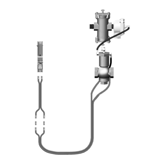
Page 22: Assembly Part Numbers & Schematics
ASSEMBLY PART NUMBERS & SCHEMATICS Blastmaster 121P Remote Control System ® Item # Part # Description Fig. 1 — 10106736 Blastmaster 121P Remote Control System – Complete ® 1012000 Abrasive Trap – Complete (see Figure 4) 1012150 1” Diaphragm Outlet Valve 10CL18 Coupled Pneumatic Control Line –... - Page 23 SCHEMATIC Figure 1: Blastmaster 121P Remote Control System ® Blastmaster 121P Remote Control System ®...
-
Page 24: 1-1/2" Inlet Valve
SCHEMATIC Figure 2: 1-1/2” Inlet Valve Item # Part # Description Fig. 2 — 1012200 1-1/2" Inlet Valve – Complete 1012101 1/4" NPT Petcock 1012051 1/4" NPT Brass Elbow (Two Required) 1012213 1/8" x 2-1/2" O-ring 1012208 1/16" x 7/16" O-ring 1012204 1-1/2"... -
Page 25: 1" Diaphragm Outlet Valve
SCHEMATIC Figure 3: 1” Diaphragm Outlet Valve Item # Part # Description Fig. 3 — 1012150 1" Diaphragm Outlet Valve Complete 1012051 Elbow 1/4" NPT x 7/16-20 Tap 1012154 1/4-20 x 1 Hex Bolt (Four Required) 1012153 1/4” Lock Washer (Four Required) 1012155 Cap Diaphragm Outlet Valve 1012152... -
Page 26: Abrasive Trap
SCHEMATIC Figure 4: Abrasive Trap Item # Part # Description Fig. 4 — 1012000 Abrasive Trap – Complete 1012006 Thumb Screw (Two Required) 1012007 3/8" x 3/8" Shoulder Bolt (Four Required) 1012003 Abrasive Trap Cap (Two Required) 1012008 Abrasive Trap Screen Gasket 1012004 Abrasive Trap Body 1012002... -
Page 27: Limited Warranty
LIMITED WARRANTY ADDITIONAL TECHNICAL DATA Seller warrants to the original purchaser that the Product covered by this Limited Warranty will remain free from defects in workmanship or material under normal commercial use and service for a period of one year from the The associations listed date of shipment to the original Purchaser. - Page 28 563.324.2519 SAFETY FAX: 563.324.6258 SERVICE & REPAIR WWW.MARCO.US VACUUMS SALES@MARCO.US Marco and Blastmaster are registered trademarks of Marco. Part #1090142_11/01/16 ® ® All other brand names or marks are used for identification purposes and are trademarks of their respective owners.
Need help?
Do you have a question about the BLASTMASTER 121P and is the answer not in the manual?
Questions and answers