Table of Contents
Advertisement
Quick Links
INSTALLATION INSTRUCTIONS
OptiNID
500 Optical Demarcation Closure
®
TABLE OF CONTENTS
GENERAL ......................................................................................................................................... 2
SPECIFICATIONS ............................................................................................................................. 2
PACKAGE CONTENTS ..................................................................................................................... 2
PACKAGE CONTENTS: ACCESSORIES ......................................................................................... 3
REQUIRED TOOLS .......................................................................................................................... 3
ADD-ON COMPONENTS .................................................................................................................. 3
CLOSURE MOUNTING ..................................................................................................................... 3
LOCK AND UNLOCK EXTERIOR DOOR ......................................................................................... 3
CABLE PREPARATION .................................................................................................................... 4
CABLE INSTALLATION .................................................................................................................... 4
PIGTAIL INSTALLATION ................................................................................................................... 5
COMPRESSION FITTING INSTALLATION ...................................................................................... 5
DISASSEMBLE COMPRESSION FITTING - CABLE REPLACEMENT .......................................... 6
SPLICING .......................................................................................................................................... 6
ADAPTER PLATE INSTALLATION .................................................................................................. 7
DISTRIBUTION CABLE INSTALLATION - PLUG AND PLAY .......................................................... 7
DISTRIBUTION CABLE INSTALLATION - SPLICE ONLY ............................................................... 8
1
Advertisement
Table of Contents

Related Manuals for AFL OptiNID 500

Summary of Contents for AFL OptiNID 500
- Page 1 INSTALLATION INSTRUCTIONS OptiNID 500 Optical Demarcation Closure ® TABLE OF CONTENTS GENERAL ............................2 SPECIFICATIONS ..........................2 PACKAGE CONTENTS ........................2 PACKAGE CONTENTS: ACCESSORIES ..................3 REQUIRED TOOLS .......................... 3 ADD-ON COMPONENTS ........................3 CLOSURE MOUNTING ........................3 LOCK AND UNLOCK EXTERIOR DOOR ..................3 CABLE PREPARATION ........................
-
Page 2: General
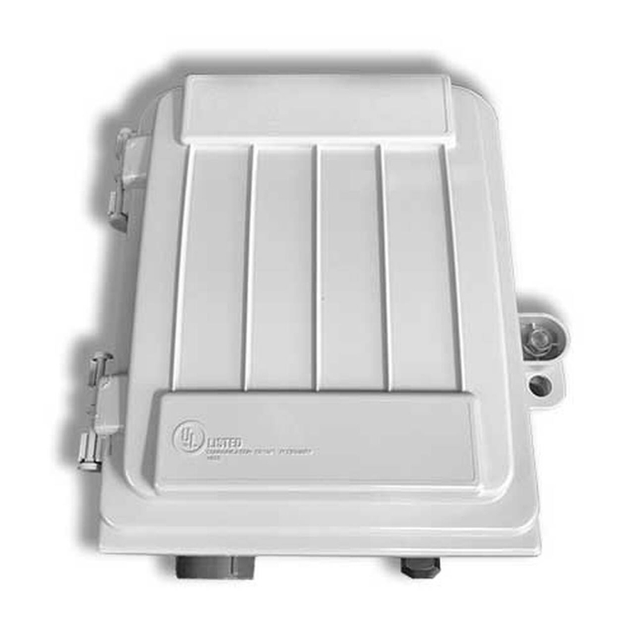
® GENERAL The OptiNID 500 Optical Demarcation Closure (OPN-500) is designed for installation in either indoor or outdoor environments. The closure is equipped with an integrated splice tray which will hold up to six single fusion splices. The closure will house one LGX 118 adapter plate allowing for up to six bulkhead connections. -
Page 3: Package Contents: Accessories
2. Press the tab located above the hex screw in to open the closure. (Figure 1) Note: A pad lock, not provided, may be utilized if additional security is desired. Screw Figure 1 © 2017, AFL, all rights reserved. Revision A, 2.16.2017 Specifications are subject to change without notice. -
Page 4: Cable Preparation
Figure 2 closure. A common ground will be established. 5. Route the buffer tube into the splice tray. © 2017, AFL, all rights reserved. Revision A, 2.16.2017 Specifications are subject to change without notice. -
Page 5: Pigtail Installation
FITTING INSTALLATION Caution: In order to avoid micro bends or fiber damage do not over-tighten the tie wraps around the fiber bundles. Figure 4 © 2017, AFL, all rights reserved. Revision A, 2.16.2017 Specifications are subject to change without notice. -
Page 6: Disassemble Compression Fitting – Cable Replacement
Note: The tab on the splice chip may be used to help organize loose tube bare fibers within the splice tray. Figure 5 6. Replace the splice tray cover. © 2017, AFL, all rights reserved. Revision A, 2.16.2017 Specifications are subject to change without notice. -
Page 7: Adapter Plate Installation
FASTConnect Mechanical Connector or FUSEConnect Splice-On Connector. The document will include the following: Figure 7 • Fiber Preparation • Fiber Termination © 2017, AFL, all rights reserved. Revision A, 2.16.2017 • Connector Assembly Specifications are subject to change without notice. -
Page 8: Distribution Cable Installation – Splice Only
For splice only applications, reference the Cable Preparation and Cable Installation sections of this documents for the distribution cable before continuing to the Splicing section of this document to complete the installation. © 2017, AFL, all rights reserved. Revision A, 2.16.2017 Specifications are subject to change without notice.
Need help?
Do you have a question about the OptiNID 500 and is the answer not in the manual?
Questions and answers