
Related Manuals for SEW-Eurodrive UFF41B

Summary of Contents for SEW-Eurodrive UFF41B
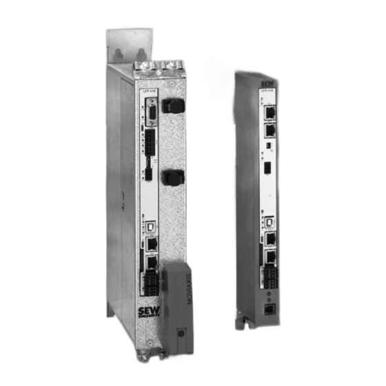
- Page 1 Drive Technology \ Drive Automation \ System Integration \ Services Fieldbus Gateway UFF41B DeviceNet and PROFIBUS DP Manual Edition 02/2009 16756428 / EN...
- Page 2 SEW-EURODRIVE – Driving the world...
-
Page 3: Table Of Contents
DIP switch S1 default IP address..............24 4.5.1 TCP / IP addressing and subnetworks ..........24 SD memory card type OMG4.B ..............26 Connecting the UFF41B fieldbus gateway to a DeviceNet network..... 27 4.7.1 Pin assignment X30D (DeviceNet) ........... 27 4.7.2 Bus termination ................. 28 4.7.3 Setting the DIP switches .............. - Page 4 10.4.1 Operating mode (DP-V1 mode) ............. 112 10.4.2 Example program for SIMATIC S7 ..........113 10.4.3 Technical data of DP-V1 for UFF41B fieldbus gateway ....114 10.4.4 Error codes of the DP-V1 services ..........115 Manual – Fieldbus Gateway UFF41B DeviceNet and PROFIBUS DP...
- Page 5 13.1 General technical data ................146 13.2 UFF41B fieldbus gateway ................147 13.3 Bus connection ..................148 13.4 Dimension drawings................... 149 13.4.1 Dimension drawing for fieldbus gateway UFF41B / UOH21B ..149 ® 13.4.2 Dimension drawing MOVIAXIS master module MXM / UFF41B . 150 14 Appendix ......................
-
Page 6: General Information
Minor injuries Specific danger, e.g. electric shock NOTICE Possible damage to property Damage to the drive system or its environment Useful information or tip. Simplifies the handling of the drive system. Manual – Fieldbus Gateway UFF41B DeviceNet and PROFIBUS DP... -
Page 7: Rights To Claim Under Limited Warranty
In such cases, any liability for defects is excluded. Copyright notice © 2008 - SEW-EURODRIVE. All rights reserved. Copyright law prohibits the unauthorized duplication, modification, distribution, and use of this document, in whole or in part. Manual – Fieldbus Gateway UFF41B DeviceNet and PROFIBUS DP... -
Page 8: Safety Notes
Use monitoring systems or mechanical protection devices as safety equipment to avoid possible damage to property or injury to people. Product names and trademarks The brands and product names contained within this manual are trademarks or regis- tered trademarks of the titleholders. Manual – Fieldbus Gateway UFF41B DeviceNet and PROFIBUS DP... -
Page 9: Waste Disposal
Waste disposal Observe the applicable national regulations. Dispose of the following materials separately in accordance with the country-specific regulations in force, as: • Electronics scrap • Plastic • Sheet metal • Copper Manual – Fieldbus Gateway UFF41B DeviceNet and PROFIBUS DP... -
Page 10: Introduction
Configure the DeviceNet master with EDS files. • Configure the PROFIBUS DP-V1 master using GSD files. Characteristics The powerful, universal fieldbus interfaces of the UFF41B option enable you to use the option to connect to higher-level automation systems via DeviceNet and PROFIBUS DP-V1. 3.2.1... -
Page 11: Monitoring Functions
As the range of functions for the control termi- nals is also guaranteed in fieldbus mode, you can continue to implement rapid stop concepts using the servo inverters/inverters connected to the fieldbus gateway. Manual – Fieldbus Gateway UFF41B DeviceNet and PROFIBUS DP... -
Page 12: Assembly And Installation Instructions
Assembly and Installation Instructions Installation options of the UFF41B fieldbus gateway Assembly and Installation Instructions This chapter contains information on the assembly and installation of the UFF41B field- ® bus gateway in a MOVIAXIS master module MXM or in an UOH21B gateway housing. -
Page 13: Voltage Supply
® • If the UFF41B fieldbus gateway is connected with DC 24 V from the MOVIAXIS switched-mode power supply, the functioning of the option is maintained after dis- connection from the power supply. This is the case if the DC link voltage is main- ®... - Page 14 MXS UFF41B L 18 X30P 1 DC 24V E DGND 3 DC 24V B 4 BGND DC 24 V supply DC 24 V for for control electronics brake supply 64424AEN Manual – Fieldbus Gateway UFF41B DeviceNet and PROFIBUS DP...
-
Page 15: Voltage Supply In The Uoh21B Gateway Housing
Connection of CAN 1 system bus / voltage supply (terminal X26) The connections for CAN 1 (X26:1/2/3 and connector X33) are connected in parallel. The UFF41B fieldbus gateway is supplied with voltage in the UOH21B gateway housing via X26:6/7. Manual – Fieldbus Gateway UFF41B DeviceNet and PROFIBUS DP... -
Page 16: Connecting Inverters And Engineering Pc
4.3.1 Functional description of the terminals, DIP switches and LEDs of the UFF41B option Connectors, LEDs and DIP switches in the upper part of the UFF41B fieldbus gateway allow for connection to the fieldbus systems DeviceNet (see section "Connecting the UFF41B fieldbus gateway to a DeviceNet network") and PROFIBUS-DP (see section... -
Page 17: Connecting Can 1 System Bus (Connector X33)
The CAN 1 system bus is not electrically isolated. Therefore, it is recommended to use the CAN 1 (X33 or X26 with UFF41B/UOH21B) interface to connect inverters via the system bus in the control cabinet. Set the P881 SBus address parameter in increasing order to values 1 - 16 if the slave unit is connected to CAN 1 or the field- bus gateway. - Page 18 There must not be any potential displacement between the units connected via the CAN 1 system bus. • Take suitable measures to avoid potential displacement, such as connecting the unit ground connectors using a separate cable. Manual – Fieldbus Gateway UFF41B DeviceNet and PROFIBUS DP...
- Page 19 Overview of system connection cables Type Part number Description ® System cable UFF41B gateway CAN 1 post connector (or CAN 2) to MOVIAXIS CAN system cable 0819 692 3 supply/regenerative power module CAN 1 system bus RJ45, length: 750 mm ®...
- Page 20 750 mm, RJ45 litz wire length: 750 mm ® ® ® CAN1 connection cable, CAN connection cable MOVIAXIS axis system to MOVIDRIVE and MOVITRAC 0819 7563 3000 mm, RJ45 litz wire length: 3000 mm Manual – Fieldbus Gateway UFF41B DeviceNet and PROFIBUS DP...
-
Page 21: Connecting Sbus Plus System Bus (Terminal X36)
The IP parameters are defined depending on DIP switch S1 (see section "DIP switches S1 default IP address"). In addition to the engineering access via terminal X37, there is another engineering ® access via PROFIBUS (see section "Operation of MOVITOOLS MotionStudio"). Manual – Fieldbus Gateway UFF41B DeviceNet and PROFIBUS DP... -
Page 22: Pin Assignment X37 (Ethernet For Engineering)
[6] Pin 6 RX- Receive Minus Connecting UFF41B fieldbus gateway to Ethernet To connect UFF41B to the Ethernet, connect the Ethernet interface X37 (RJ45 plug connector) to the other network stations using a category 5, class D twisted-pair cable in accordance with IEC 11801 edition 2.0. The interface supports auto crossing and high auto negotiation for baud rate and duplex mode. -
Page 23: Status Led Of The Uff41B Fieldbus Gateway
Gateway program is running. No gateway program is loaded. Load a gateway program into the controller. Flashing orange Program has stopped. Bootloader update required (see section (1 Hz) "SD memory card type OMG4.B") Manual – Fieldbus Gateway UFF41B DeviceNet and PROFIBUS DP... -
Page 24: Dip Switch S1 Default Ip Address
Standard gateway: 1.0.0.0 Bottom The IP parameters defined on the memory card of the UFF41B gateway are used. The IP parameters for engineering interface X37 are entered in the file "...\Sys- tem\NetConfig.cfg" in section "Ethernet 2". You can adjust the file using a text editor (e.g. - Page 25 11111111 11111111 11111111 10000000 The class C network with the address 192.168.10. is further subdivided into 255.255.255.128 using the subnetwork mask. Two networks are created with the address 192.168.10.0 and 192.168.10.128. Manual – Fieldbus Gateway UFF41B DeviceNet and PROFIBUS DP...
-
Page 26: Sd Memory Card Type Omg4.B
The SD memory card type OMG4.B is included in the scope of delivery of the UFF41B fieldbus gateway. Only use type OMG4.B memory cards in a UFF41B fieldbus gateway. -
Page 27: Connecting The Uff41B Fieldbus Gateway To A Devicenet Network
X30D 61612BXX The UFF41B option is opto-decoupled on the driver side in accordance with the DeviceNet specification (Volume I, Chapter 9). This means the CAN bus driver must be powered with 24 V voltage via the bus cable. The cable to be used is also described in the DeviceNet specification (Volume I, Appendix B). -
Page 28: Bus Termination
= Baud rate setting 64419AXX Setting the MAC The MAC ID (Media Access Control Identifier) is set on the UFF41B option using DIP switches 2 in a binary coded manner. The MAC ID represents the node address of the UFF41B. The UFF41B supports the address range 0 - 63. - Page 29 250 kBaud 500 kBaud Invalid A maximum of 64 DeviceNet data words can be exchanged between the DeviceNet module and the UFF41B option. The number is set using the DeviceNet scanner. Manual – Fieldbus Gateway UFF41B DeviceNet and PROFIBUS DP...
-
Page 30: Status Led In Devicenet Operation
The UFF41B fieldbus gateway has four two-color LEDs for diagnostic of the DeviceNet system; they indicate the current status of the UFF41B and the DeviceNet system. The unit status corresponding to the status of the LED is described in chapter "Error diagnostics". - Page 31 Assembly and Installation Instructions Connecting the UFF41B fieldbus gateway to a DeviceNet network L14 LED (BIO) The L14 (bit-strobe I/O) LED monitors the bit-strobe I/O connection. Status of the Status Meaning L14 LED Flashing green DUP-MAC check Unit is performing DUP-MAC check...
-
Page 32: Connecting The Uff41B Fieldbus Gateway To A Profibus Network
Assembly and Installation Instructions Connecting the UFF41B fieldbus gateway to a PROFIBUS network Connecting the UFF41B fieldbus gateway to a PROFIBUS network The following sections describe the terminals, DIP switches, and LEDs relevant for PROFIBUS operation. Front view Designation Function... - Page 33 Assembly and Installation Instructions Connecting the UFF41B fieldbus gateway to a PROFIBUS network UFF41B gateway As a rule, the UFF41B fieldbus gateway is connected to the PROFIBUS system using a and PROFIBUS shielded twisted-pair cable. Observe the maximum supported transmission rate when connection selecting the bus connector.
-
Page 34: Status Led In Profibus Operation
The UFF41B fieldbus gateway has two two-color LEDs for diagnostic of the PROFIBUS system. They indicate the current status of the UFF41B and the PROFIBUS system. The unit status corresponding to the status of the LED is described in chapter "Error diagnostics". -
Page 35: Shielding And Routing Bus Cables
In case of fluctuations in the earth potential, a compensating current may flow via the bilaterally connected shield that is also connected to the protective earth (PE). Make sure you supply adequate equipotential bonding according in accordance with relevant VDE regulations in such a case. Manual – Fieldbus Gateway UFF41B DeviceNet and PROFIBUS DP... -
Page 36: Configuring The Ufx41B Fieldbus Gateway And The Inverter
Description of the gateway functions 5.1.1 Introduction With the UFF41B and UFR41B fieldbus gateways, SEW-EURODRIVE offers innovative solutions for integrating SEW inverter technology in fieldbus systems. For this purpose, process data of the higher-level control in the fieldbus gateway are processed and sent via CAN (SBus) to the devices connected to the fieldbus gateway. - Page 37 ® To ensure successful communication and configuration of MOVIAXIS units, the ® MOVIAXIS parameter setting level must be set to "Planning Engineer". Manual – Fieldbus Gateway UFF41B DeviceNet and PROFIBUS DP...
-
Page 38: Customized Configuration
Changes made to the process data configuration in the fieldbus gateway will take effect in the fieldbus gateway by pressing the [Apply configuration] button. Manual – Fieldbus Gateway UFF41B DeviceNet and PROFIBUS DP... -
Page 39: Configuring Fieldbus Gateway And Slave Units
• If the application requires axis-to-axis communication, use the CAN2 bus of the axis ® ® module for MOVIAXIS , and the free CAN bus for MOVIDRIVE Manual – Fieldbus Gateway UFF41B DeviceNet and PROFIBUS DP... - Page 40 DIØØ input terminal ® (function /CONTROLLER INHIBIT) for MOVIDRIVE B, and DI01 = CW/stop for ® MOVITRAC B to a +24 V signal and to program the remaining terminals to NO FUNCTION. Manual – Fieldbus Gateway UFF41B DeviceNet and PROFIBUS DP...
-
Page 41: Data Backup
The parameter sets of the slave units and the config- uration data of the UFx41B fieldbus gateway are centrally saved on the SD memory card of the fieldbus gateway and will be used when replacing a unit. Manual – Fieldbus Gateway UFF41B DeviceNet and PROFIBUS DP... - Page 42 The user has to restart the SBus process data once data backup is completed. Bit 9 ("configured") in the gateway status indicates that the data memory contains valid data. Manual – Fieldbus Gateway UFF41B DeviceNet and PROFIBUS DP...
- Page 43 If timeout monitoring is disabled for a slave, no slave timeout will be signaled. This is the reason why no unit replacement verification is carried out during gateway operation. The unit replacement function during startup of the fieldbus gateway is not affected by this setting. Manual – Fieldbus Gateway UFF41B DeviceNet and PROFIBUS DP...
-
Page 44: Startup Procedure
2. Create a project with name and storage location. 3. Set up communication for communicating with your units. 4. Scan the network (unit scan). To do so, click the [Start network scan] button [1] in the toolbar. 64334AXX Manual – Fieldbus Gateway UFF41B DeviceNet and PROFIBUS DP... - Page 45 As a result you will see a number of unit-specific tools to execute various functions with the units. 7. Open the "UFx Gateway Configurator" tool (see following figure) 12104AEN Manual – Fieldbus Gateway UFF41B DeviceNet and PROFIBUS DP...
-
Page 46: Configuring The Fieldbus Gateways
The CAN cycle time can be reduced by dividing the slave units among the two CAN interfaces of the fieldbus gateway. The data transmission performance can be increased in this way. 12103AEN Manual – Fieldbus Gateway UFF41B DeviceNet and PROFIBUS DP... -
Page 47: Last Settings In The Slave Units
"autosetup process data" for this unit is set to "ON". Only the process data objects required for communication ® between fieldbus gateway and MOVIAXIS axis module are configured. Manual – Fieldbus Gateway UFF41B DeviceNet and PROFIBUS DP... - Page 48 – P100 control signal source – P101 setpoint source – P880 / P890 SBus protocol – P881 / P891 SBus address – P884 / P894 SBus baud rate – P883 / P892 SBus timout interval Manual – Fieldbus Gateway UFF41B DeviceNet and PROFIBUS DP...
-
Page 49: Monitoring And Controlling Process Data
In the UFx Gateway Configurator, open the "Process data monitor" tab (see following diagnostics figure). 12084AEN Check the data between fieldbus gateway and master controller. To apply different number formats to the individual numerical fields, make a right mouse click. Manual – Fieldbus Gateway UFF41B DeviceNet and PROFIBUS DP... - Page 50 "Parameter tree" tool in parameter group 09 "Bus diagnostics" (see following figure). The two tools "UFx Gateway Configurator" and "Parameter tree" can be open at the same time (see following figure). 12086AEN Manual – Fieldbus Gateway UFF41B DeviceNet and PROFIBUS DP...
- Page 51 Activate force mode and enter the values in the now active fields. Clicking the "Send process data" button will send the entered values to the slave units via SBus instead of the valued received via fieldbus. Process input data cannot be specified manually. Manual – Fieldbus Gateway UFF41B DeviceNet and PROFIBUS DP...
-
Page 52: Saving Inverter Data In The Fieldbus Gateway And Using Movitools ® Motionstudio
4. Drag the scanned unit from the network view into project view (drag and drop) or select the [Project unit] command from the context menu. 12116AEN This opens the "Project unit" window. 5. Use the name (signature) of the unit that is accessible online. Manual – Fieldbus Gateway UFF41B DeviceNet and PROFIBUS DP... - Page 53 The mini symbol on the unit node will then disappear in the network view. 8. Save your project. The parameter is then transferred from the working memory to the parameter file where it is permanently saved. Manual – Fieldbus Gateway UFF41B DeviceNet and PROFIBUS DP...
-
Page 54: Error Processing And Status Messages
(bit 3), the slave where this error has occurred can be determined from the status of the slaves. Bits indicating an error are reset during error reset (bits 0 - 5, bit 11, bit 15, bit 30). Manual – Fieldbus Gateway UFF41B DeviceNet and PROFIBUS DP... - Page 55 Status word settings: – Selection field "Layout": Progr. layout/fault code – Selection field "Bit 5: Malfunction" This status word is linked with the corresponding output process data object (see following figure). 12109AEN Manual – Fieldbus Gateway UFF41B DeviceNet and PROFIBUS DP...
- Page 56 A sychronization telegram is also transmitted to ensure data consistency: SyncID for CAN 1 and CAN 2 = 1 ® This calculation directive ensures the consistency of IDs calculated for MOVIAXIS using the "Single-axis positioning" technology editor. Manual – Fieldbus Gateway UFF41B DeviceNet and PROFIBUS DP...
-
Page 57: Configuration And Startup On Devicenet Fieldbus
This chapter provides you with information on project planning for the DeviceNet master and startup of the UFF41B fieldbus gateway for fieldbus operation. The current versions of the EDS files for UFF41B are available on the SEW website (http://www.sew-eurodrive.de) under the heading "Software". -
Page 58: Configuring Plc And Master (Devicenet Scanner)
(in the example: 02) must be identical with the MAC ID set on UFF41B using DIP switches. If the required devices are not in the selection list, corresponding EDS files have to be registered via [Tools] / [Wizard]. - Page 59 Configuring PLC and master (DeviceNet scanner) In online mode, you can check and set the "Pd configuration" (process data configura- tion) of UFF41B when reading out the device properties (see following figure). 11959AXX The parameter "Pd configuration" indicates the number (1 ... 64) of process data words set (16-bit) and defines the I/O parameters for the DeviceNet scanner (see following figure).
- Page 60 (input & output as byte arrays) for each DeviceNet device. The tag name contains the MAC ID of the DeviceNet unit and POL_I for polled input data or POL_O for polled output data (see following figure). 11961AXX Manual – Fieldbus Gateway UFF41B DeviceNet and PROFIBUS DP...
-
Page 61: Project Planning Examples In Rslogix5000
(PD) in the inverters. 5. In order to copy the data of the UFF41B fieldbus gateway to the new data structure, CPS commands are added into the "MainRoutine" that reads the data from the local I/O (see following figure). - Page 62 Make sure that this CPS command is executed after the automatically generated (by DeviceNet Tag Generator) DNet_ScannerInputsRoutine. 11963AXX In order to copy the data from the new data structure to the UFF41B fieldbus gate- way, CPS commands are added into the "MainRoutine" that writes the data to the local I/O.
- Page 63 6. Now save the project and transfer it to the PLC. Set the PLC to Run Mode and set the Scanner CommandRegister.Run to "1" to activate the data exchange via DeviceNet. You can now read the actual values from the UFF41B fieldbus gateway and write setpoint values. 11965AXX The process data should correspond with the values displayed in the Gateway ®...
-
Page 64: Access To Uff41B Fieldbus Gateway Parameters
6.3.2 Access to UFF41B fieldbus gateway parameters In order to get an easy-to-use read access to parameters of the UFF41B fieldbus gateway via explicit messages and the register object, follow the following steps: 1. Create a user-defined data structure "SEW_Parameter_Channel" (see following figure). - Page 65 5. The target device is to be specified on the Communication tab (see following figure). 11768AXX The path consists of: • Name of the scanner (e. g. DNet_Scanner) • 2 (always 2) • Slave address (e. g. 11) Manual – Fieldbus Gateway UFF41B DeviceNet and PROFIBUS DP...
- Page 66 On response to the read request, ReadParameterResponse.Index should indicate the read index and ReadParameterResponse.Data should contain the read data. In this example, the timeout interval of the UFF41B fieldbus gateway (index 8606) set by the scanner has been read (012C = 0.3 s).
-
Page 67: Access To Unit Parameters Of Lower-Level Units
Access to unit parameters of, for example MOVITRAC B connected to the UFF41B fieldbus gateway via SBus, is the same as access to unit parameters of the UFF41B fieldbus gateway itself (see chapter "Accessing parameters of the UFF41B fieldbus gateway"). - Page 68 – Source Length = 12 – Destination = WriteParameterResponse.Index – Class = 7 – Instance = 2 – Attribute = 4 – Service Code = 10 The service type is set automatically. Manual – Fieldbus Gateway UFF41B DeviceNet and PROFIBUS DP...
- Page 69 WriteParameterResponse.Data should contain the written data. ® In this example, MOVITRAC B connected to a CAN 1 system bus of the UFF41B option with SBus address 1 wrote the value 150 rpm toP160 Fixed setpoint n11 (index 8489).
-
Page 70: Devicenet Operating Characteristics
If the value is set greater than four, the process data length will be automatically limited to four. Timeout The timeout is triggered by the UFF41B option. The timeout interval must be set by the response with master after the connection has been established. The DeviceNet specification refers to polled I/O an "expected packet rate"... - Page 71 Flashing red NOTICE The LED L14 (BIO) on the front of the UFF41B option can be used for distinguishing between the timeout triggered by the bit-strobe telegram and a real timeout in the connection. The LED L14 (BIO) lights up green when bit-strobe messages are received cyclically.
- Page 72 DeviceNet Operating Characteristics Process data exchange Timeout The timeout is triggered by the UFF41B option. The timeout interval must be set by the response with master after the connection has been established. The DeviceNet specification refers to bit-strobe I/O an "expected packet rate" rather than a timeout interval in this case. The expected pack-...
-
Page 73: The Common Industrial Protocol (Cip)
The Common Industrial Protocol (CIP) DeviceNet is integrated into the Common Industrial Protocol (CIP). In the Common Industrial Protocol, all unit data can be accessed via objects. The objects listed in the following table are integrated in the UFF41B option. Class [hex] Name... - Page 74 0000 Unknown 0010 At least one faulty IO connection 0101 No IO connection established 0110 At least one IO connection active Supported services Service code [hex] Service name Instance Reset Get_Attribute_Single Manual – Fieldbus Gateway UFF41B DeviceNet and PROFIBUS DP...
- Page 75 MAC-ID switch value DIP switch setting for MAC ID Baud rate switch value Actual DIP switch settings for baud rate Supported services Service code [hex] Service name Class Instance Get_Attribute_Single Set_Attribute_Single Manual – Fieldbus Gateway UFF41B DeviceNet and PROFIBUS DP...
- Page 76 Produced connection path len Produced connection path Consumed connection path len Consumed connection path Production inhibit time Supported services Service code [hex] Service name Instance 0x05 Reset 0x0E Get_Attribute_Single 0x10 Set_Attribute_Single Manual – Fieldbus Gateway UFF41B DeviceNet and PROFIBUS DP...
- Page 77 WRITE parameter OUTPUT READ WRITE VOLATILE parameter INPUT READ MINIMUM Invalid INPUT READ MAXIMUM Invalid INPUT READ DEFAULT Invalid INPUT READ SCALING Invalid INPUT READ ATTRIBUTE Invalid INPUT READ EEPROM Invalid Manual – Fieldbus Gateway UFF41B DeviceNet and PROFIBUS DP...
- Page 78 Input Get_Attribute_Single READ SCALING (Instance 7) Input Get_Attribute_Single READ ATTRIBUTE (Instance 8) Input Get_Attribute_Single READ EEPROM (Instance 9) DeviceNet (CIP) SEW fieldbus profile 62367AEN Figure 2: Description of the parameter channel Manual – Fieldbus Gateway UFF41B DeviceNet and PROFIBUS DP...
- Page 79 Subaddress 2 BYTE Reserved (must be "0") Subchannel 2 BYTE Reserved (must be "0") The subchannels and subaddresses apply to the UFF41B fieldbus gateway depending on the lower-level bus system. Subchannel 1 Interface Value range subaddress 1 UFF41B itself Reserved...
- Page 80 The Common Industrial Protocol (CIP) Parameter object • The fieldbus parameters of the UFF41B option can be addressed directly via the instance using the parameter object. • In exceptional cases, you can also use the parameter object to access SEW parameters.
- Page 81 The data format for these instances deviates from the SEW fieldbus profile to meet the DeviceNet specification. Supported services Service code [hex] Service name Class Instance Get_Attribute_Single Set_Attribute_Single Manual – Fieldbus Gateway UFF41B DeviceNet and PROFIBUS DP...
-
Page 82: Return Codes Of The Parameterization Via Explicit Messages
The coding of these return codes is described in the DeviceNet specification (see section "General Error Codes"). Timeout of The timeout is triggered by the UFF41B option. The timeout interval must be set by the explicit master after the connection has been established. The DeviceNet specification refers to messages an "expected packet rate"... - Page 83 Reserved by DeviceNet for additional definitions D0 - DF Reserved for Object Use this area if an occurring error cannot be entered in one of Class and service the error groups listed above. errors Manual – Fieldbus Gateway UFF41B DeviceNet and PROFIBUS DP...
- Page 84 FCS Error 0x13 0xD1 0xF5 PB Init 0x14 0xF6 SBUS - Illegal Fragment Count 0x15 0xF7 SBUS - Illegal Fragment Type 0x16 0xF8 Access denied 0x17 0xF9 - FE Not used Manual – Fieldbus Gateway UFF41B DeviceNet and PROFIBUS DP...
- Page 85 Parameter access only via RS485 diagnostics interface Parameter is access-protected Controller inhibit required Invalid value for parameter Factory setting was activated Parameter was not saved in EEPROM Parameter cannot be changed with enabled output stage Manual – Fieldbus Gateway UFF41B DeviceNet and PROFIBUS DP...
-
Page 86: Terms And Definitions
Provides a service for setting up a connection. Reset Provides a service for resetting an error. Rung SLC500 program line Service Service performed via bus, e.g. read service, write service, etc. Set_Attribute_Single Write service for a parameter. Manual – Fieldbus Gateway UFF41B DeviceNet and PROFIBUS DP... -
Page 87: Configuration And Startup On The Profibus Dp-V1 Fieldbus
Siemens S7 hardware configuration for all S7 DP masters Do not change or expand entries in the GSD file! SEW assumes no liability for UFF41B fieldbus gateway or connected inverter malfunctions caused by a modified GSD file. General configu-... - Page 88 +---Adv. Gateway UFF The installation of the new GSD file is now complete. Configuration Proceed as follows for configuring the UFF41B fieldbus gateway with PROFIBUS DP with STEP7 interface: 1. Use drag and drop to add the interface module with the name "Adv. Gateway UFF"...
- Page 89 Configuration and Startup on the PROFIBUS DP-V1 Fieldbus Configuring a PROFIBUS DP master 2. The UFF41B fieldbus gateway is now preconfigured with the 3PD configuration. To change the PD configuration, you have to delete the 3 PD module in slot 3. Next, add another PD module (e.g.
- Page 90 [1] and 'Q Address' [2] columns. DP configuration To enable the UFF41B fieldbus gateway to support the type and number of the input and output data used for transmission, the DP master must transmit the corresponding DP configuration to the UFF41B fieldbus gateway. The configuration telegram comprises the DP configurations for slots 1 to 18.
- Page 91 Data integrity Consistent data is data that always has to be transmitted between the higher-level controller and the UFF41B fieldbus gateway as one block and must never be transmitted separately. Data integrity is particularly important for transmitting position values or complete positioning tasks.
-
Page 92: Profibus Dp-V1 Operating Characteristics
PROFIBUS DP. Process data exchange with the UFF41B fieldbus gateway The UFF41B fieldbus gateway is controlled via the process data channel which is up to 64 I/O words in length. These process data words are reproduced in the I/O or peripheral area of the UFF41B fieldbus gateway, for example when a programmable logic controller is used as the DP master. -
Page 93: Profibus Dp Timeout
Refer to the online help for STEP7 for further information about the system functions. //Start of cyclical program processing in OB1 BEGIN NETWORK TITLE = Copy PI data from the type DHF41B/UFF41B control card to DB3, words 0 - CALL SFC 14 (DPRD_DAT) //Read DP Slave Record LADDR... -
Page 94: Functions Of Profibus Dp-V1
The main features of PROFIBUS DP-V1 are explained below. C1-Master C2-Master C2-Master Cyclic OUT Data Param PROFIBUS DP-V1 Param Cyclic IN Data Acyclic DP-V1 C2-Services Acyclic DP-V1 Acyclic DP-V1 C1-Services C2-Services Drive 58617AXX Manual – Fieldbus Gateway UFF41B DeviceNet and PROFIBUS DP... -
Page 95: Class 1 Master (C1 Master)
DP-V1 parameter channel for drives as of V3.1 in the PROFIdrive profile drive engineering of the PROFIBUS user organization. Different procedures for accessing parameter data in the inverter are provided via this parameter channel. Manual – Fieldbus Gateway UFF41B DeviceNet and PROFIBUS DP... -
Page 96: Dp-V1 Services
DP-V1 operation using the "DDLM_SlaveDiag" DP-V0 service. DP-V1 alarm handling has not been defined for drive engineering as an inverter does not usually transfer its status information via cycli- cal process data communication. Manual – Fieldbus Gateway UFF41B DeviceNet and PROFIBUS DP... -
Page 97: Features Of Sew Fieldbus Interfaces
8 Byte Param PROFIBUS DP-V1 Acyclic DP-V1 Acyclic DP-V1 C2 Services C2 Services Cyclic IN/Out cyclic Process Data Parameter Buffer Drive System 61535AXX Figure 4: Parameter setting channels for PROFIBUS DP-V1 Manual – Fieldbus Gateway UFF41B DeviceNet and PROFIBUS DP... -
Page 98: Structure Of The Dp-V1 Parameter Channel
® • 8-byte MOVILINK parameter channel with all the services supported by the SEW device, such as – READ parameter – WRITE parameter – WRITE parameter volatile – etc. Manual – Fieldbus Gateway UFF41B DeviceNet and PROFIBUS DP... - Page 99 0x00 - 0xEA Quantity 0 - 234 Error value Unsigned16 0x0000 - 0x0064 PROFIdrive error codes ® 0x0080 + MOVILINK -Additional Code Low ® For SEW MOVILINK 16 Bit error value Manual – Fieldbus Gateway UFF41B DeviceNet and PROFIBUS DP...
-
Page 100: Parameterization Procedure Via Data Set 47
Parameter Processing READ.res(-) without data READ.req DS47 without data Parameter Response Parameter READ.res(+) Response with data (parameter response) 53126AXX Figure 5: Telegram sequence for parameter access via PROFIBUS DP-V1 Manual – Fieldbus Gateway UFF41B DeviceNet and PROFIBUS DP... -
Page 101: Dp-V1 Master Processing Sequence
Check Write. Write.response response negative Write.response positive Send DS_Read.req with parameter data Read. response status conflict? Other error or timeout Parameter transfer ok, Parameter transfer data available aborted with ERROR 53127AEN Manual – Fieldbus Gateway UFF41B DeviceNet and PROFIBUS DP... -
Page 102: Addressing Connected Inverters
With the setting Axis = 0, the parameters of the fieldbus gateway can be accessed ® MOVIDRIVE directly. To being able to access slave units connected to the UFF41B fieldbus gateway, inverter at the setting must be Axis = SBus address. SBus address 15 must not be used when en- PROFIBUS DP-V1 gineering via PROFIBUS or parameter services via PROFIBUS. -
Page 103: Movilink ® Parameter Requests
The following table shows the coding of the READ.req USER DATA including the DP- V1 header. Service: READ.request Description Slot_Number Random, (is not evaluated) Index Index of the data set; constant index 47 Length Maximum length of response buffer in the DP-V1 master Manual – Fieldbus Gateway UFF41B DeviceNet and PROFIBUS DP... - Page 104 Send "WRITE parameter volatile" order Service: WRITE.request Description Slot_Number Random, (is not evaluated) Index Index of the data set; constant index 47 Length 16-byte user data for order buffer Manual – Fieldbus Gateway UFF41B DeviceNet and PROFIBUS DP...
- Page 105 Mirrored reference number from the parameter setting request ® Response ID 0x40 Positive MOVILINK response Axis 0x01 Mirrored axis number; 1 = SBus address 1 No. of parameters 0x01 1 parameter Manual – Fieldbus Gateway UFF41B DeviceNet and PROFIBUS DP...
- Page 106 Parameter may only be changed when auto setup is deactivated 0x0505 Incorrect coding of management and reserved byte 0x0602 Communication error between inverter system and fieldbus interface 0x0502 Timeout of secondary connection (e.g. during reset or with Sys-Fault) Manual – Fieldbus Gateway UFF41B DeviceNet and PROFIBUS DP...
-
Page 107: Profidrive Parameter Orders
Access to parameter value No. of elements 0x00 0 = access to direct value, no subelement ® 6, 7 Parameter Number 0x206C MOVILINK index 8300 = "Firmware version" 8, 9 Subindex 0x0000 Subindex 0 Manual – Fieldbus Gateway UFF41B DeviceNet and PROFIBUS DP... - Page 108 Value Hi 0x311C Higher-order part of the parameter 8, 9 Value Lo 0x7289 Lower-order part of the parameter Decoding: 0x 311C 7289 = 823947913 dec >> firmware version 823 947 9.13 Manual – Fieldbus Gateway UFF41B DeviceNet and PROFIBUS DP...
- Page 109 The following table shows the coding of the WRITE.req user data including the DP-V1 header. Field Value Description Function_Num READ.req Slot_Number Slot_Number not used Index Index of the data set Length Maximum length of response buffer in the DP-V1 master Manual – Fieldbus Gateway UFF41B DeviceNet and PROFIBUS DP...
- Page 110 1 error code ® 6, 7 Error value 0x0811 MOVILINK return code e.g. error class 0x08, Add. code 0x11 ® (see section "MOVILINK configuration return codes for DP-V1" on page 106) Manual – Fieldbus Gateway UFF41B DeviceNet and PROFIBUS DP...
- Page 111 0x19 Axis does not exist Access to an axis that does not exist up to 0x64 Reserved 0x65..0xFF Depending on manufacturer Manual – Fieldbus Gateway UFF41B DeviceNet and PROFIBUS DP...
-
Page 112: Configuring A C1 Master
10.4 Configuring a C1 master A special GSD file SEW_600D.GSD is required for configuring a DP-V1 C1 master. This file activates the DP-V1 functions of the UFF41B. The functions of the GSD file and the UFF41B firmware must correspond with one another. -
Page 113: Example Program For Simatic S7
(www.sew-eurodrive.de) under "Software". This example is a special and free service that demonstrates only the basic approach to generating a PLC program. SEW is not liable for the contents of the sample program. • Calling the function module: 12101AXX Manual – Fieldbus Gateway UFF41B DeviceNet and PROFIBUS DP... -
Page 114: Technical Data Of Dp-V1 For Uff41B Fieldbus Gateway
"dwData": (DWORD)bError = 0 => Parameter value after READ service bError = 1 => S7 error code 65377AEN 10.4.3 Technical data of DP-V1 for UFF41B fieldbus gateway GSD file for DP-V1: SEW_600D.GSD Module name for project planning: Adv. Gateway UFF... -
Page 115: Error Codes Of The Dp-V1 Services
0x0 = read constraint conflict 0x1 = write constraint conflict 0x2 = resource busy 0x3 = resource unavailable 0x4 - 0x7 = reserved 0x8 - 0xF = user specific 0xD - 0xF = user specific Manual – Fieldbus Gateway UFF41B DeviceNet and PROFIBUS DP... -
Page 116: Operating Movitools ® Motionstudio
MotionStudio allowing you to use the units to execute functions: • MotionStudio ® • MOVITOOLS ® All functions communicate using tools. MOVITOOLS MotionStudio provides the right tools for every unit type. Manual – Fieldbus Gateway UFF41B DeviceNet and PROFIBUS DP... -
Page 117: First Steps
3. Select the unit you want to configure. 4. Open the context menu with a right mouse click. As a result you will see a number of unit-specific tools to execute various functions with the units. Manual – Fieldbus Gateway UFF41B DeviceNet and PROFIBUS DP... -
Page 118: Communication Mode
• To transfer the changes to the RAM [2], perform an upload. • Save your project so that the changes can be stored on the hard disk [1] of your PC. Manual – Fieldbus Gateway UFF41B DeviceNet and PROFIBUS DP... -
Page 119: Selecting Communication Mode (Online Or Offline)
"Offline" [2] for functions (offline tools) that should influence your project. 64337AXX 2. Select the unit node. 3. Right-click to open the context menu and display the tools for configuring the unit. Manual – Fieldbus Gateway UFF41B DeviceNet and PROFIBUS DP... -
Page 120: Communication Via Usb (Direct)
2. Insert the B connector of the USB cable [2] into the USB port on your fieldbus gate- way [3]. 3. Connect the SBus interface of the fieldbus gateway [3] with the SBus interface of the lower-level unit [5]. Manual – Fieldbus Gateway UFF41B DeviceNet and PROFIBUS DP... -
Page 121: Installing The Driver
You need a USB connection between your PC and the units you want to configure. Proceed as follows to configure USB communication: 1. Click "Configure communication connections" [1] in the toolbar. 64341AXX Configure communication connections Manual – Fieldbus Gateway UFF41B DeviceNet and PROFIBUS DP... - Page 122 In the example, "USB" is activated as the communication type for the first communi- cation channel [2]. 3. Press the [Edit] button [3] on the right side of the "Configure communication connections" window. Manual – Fieldbus Gateway UFF41B DeviceNet and PROFIBUS DP...
-
Page 123: Usb Communication Parameters
Communication parameters Description Note Timeout Waiting time in milliseconds that Default setting: 350 ms the master waits for a response from a slave after it has sent a request. Manual – Fieldbus Gateway UFF41B DeviceNet and PROFIBUS DP... -
Page 124: Communication Via Ethernet
The UFx41B can be connected either directly to the PC or via an Ethernet network. The Ethernet interface X37 supports auto crossing and auto negotiation for baud rate and duplex mode. Set the IP parameters of UFF41B as described in chapter 4.5. Adjusting the... -
Page 125: Configuring The Communication Channel Via Ethernet
4. Set up the SMLP protocol. To do so, select the "SMLP settings" tab. 5. Set the parameters. Follow the instructions described in the section 'Setting parameters for SMLP'. ® SMLP stands for Simple MOVILINK Protocol. It is the unit protocol from SEW- EURODRIVE. Manual – Fieldbus Gateway UFF41B DeviceNet and PROFIBUS DP... -
Page 126: Setting Communication Parameters For Smlp
PC that is running on MOVITOOLS MotionStudio. • If you have units that are OUTSIDE the local network segment, add the IP addresses of these units to the list of SMLP servers. Manual – Fieldbus Gateway UFF41B DeviceNet and PROFIBUS DP... - Page 127 Operating MOVITOOLS® MotionStudio Communication via Ethernet 2. To add an IP address, open the context menu and select [Add IP address] [1]. 64352AEN 3. Enter the IP address [2] Manual – Fieldbus Gateway UFF41B DeviceNet and PROFIBUS DP...
-
Page 128: Communication Via Profibus Dp/Dp-V1
SIMATIC S7 [2] does not perform any routing. Advantage The C2 master works independently of the C1 master. This means you can establish a communication with your units even when the C1 master fails. Manual – Fieldbus Gateway UFF41B DeviceNet and PROFIBUS DP... -
Page 129: Additionally Required Hardware And Software
Do the following to install the additionally required hardware and software: hardware and 1. Observe the documentation provided by Siemens for the hardware and software software products used. 2. Install the PROFIBUS master card. 3. Install the software. Manual – Fieldbus Gateway UFF41B DeviceNet and PROFIBUS DP... -
Page 130: Parameterize C2 Master With Simatic Net
You have opened the "Set PG/PC interface" program from SIMATIC STEP 7 and have therefore occupied the access path. • Start the "Set PG/PC Interface" program from the Windows Start menu. Manual – Fieldbus Gateway UFF41B DeviceNet and PROFIBUS DP... - Page 131 4. Set the baud rate (transmission speed) matching your PROFIBUS network. If you operate a C1 master, set the baud rate of the C1 master. 5. Select "DP" as the profile or set the bus timing according to the existing PROFIBUS network. Manual – Fieldbus Gateway UFF41B DeviceNet and PROFIBUS DP...
- Page 132 5. Make sure that all bus stations were parameterized correctly. ® 6. Open the MOVITOOLS MotionStudio engineering software. ® 7. Set the communication parameters in MOVITOOLS MotionStudio. Refer to the next section "Configuring communication via PROFIBUS". Manual – Fieldbus Gateway UFF41B DeviceNet and PROFIBUS DP...
-
Page 133: Configuring Communication Via Profibus
MotionStudio and create a project following the instructions described in the section "First Steps". 3. Click on "Configure communication plugs" [1] in the toolbar. 64620AXX Configure communication connections This will open the "Configure communication plugs" window. Manual – Fieldbus Gateway UFF41B DeviceNet and PROFIBUS DP... - Page 134 4. From the list [1], select "PROFIBUS" as the communication type. 64619AEN "Communication type" selection list "Activated" check box "Edit" button In the example, "PROFIBUS" is activated as the communication type for the first communication channel [2]. Manual – Fieldbus Gateway UFF41B DeviceNet and PROFIBUS DP...
-
Page 135: Communication Parameters For Profibus Dp/Dp-V1
Select the "Start automatically" The Windows status bar displays check box if you want to launch the active PROFIBUS server the PROFIBUS server every time the SEW Communication Server is started. Manual – Fieldbus Gateway UFF41B DeviceNet and PROFIBUS DP... -
Page 136: Executing Functions With The Units
5. Expand the "Parameter tree" up to the node you require. 12079AEN 6. Double-click to display a particular group of unit parameters. 7. Press the enter key to finalize any changes you make to numerical values in the input fields. Manual – Fieldbus Gateway UFF41B DeviceNet and PROFIBUS DP... -
Page 137: Starting Up The Units (Online)
For detailed information about the unit parameters, refer to parameter list for the unit. ® • For detailed information about using the startup wizard, refer to the MOVITOOLS MotionStudio online help. Manual – Fieldbus Gateway UFF41B DeviceNet and PROFIBUS DP... -
Page 138: Special Configuration And Diagnostics Tools
11.8 Special configuration and diagnostics tools To configure the UFF41B in gateway operation, you can use the context menu to start both the "UFx gateway configurator" and the parameter tree. In addition to configuration, this function provides information for diagnostics of gateway operation and displays the transmitted process data. -
Page 139: Troubleshooting
[1] with the associated suberror number [2]. In the fol- lowing tables, this suberror number [2] is given in hexadecimal notation. It can be used to generate a suberror code referring to the relevant slave unit (see figure below). 64881AEN Manual – Fieldbus Gateway UFF41B DeviceNet and PROFIBUS DP... -
Page 140: General Errors Of The Fieldbus Gateway
SBus address. Check the SBus installation and the terminating resistors. Manual – Fieldbus Gateway UFF41B DeviceNet and PROFIBUS DP... -
Page 141: Error During Process Data Processing
Error while initializing CAN 239.10710 Process data are not Check the SBus installation and 1 or CAN 2 system bus. initialized. the terminating resistors. Check whether several slave units use the same SBus addresses. Manual – Fieldbus Gateway UFF41B DeviceNet and PROFIBUS DP... -
Page 142: Error During Unit Replacement
CAN bus. Use the second CAN bus of ® ® MOVIDRIVE B or MOVIAXIS for this axis-to-axis communication. Manual – Fieldbus Gateway UFF41B DeviceNet and PROFIBUS DP... -
Page 143: Diagnostic Procedure For Operation On Devicenet
• The UFF41B fieldbus gateway does not operate on the DeviceNet • No drive can be controlled with the DeviceNet master via the UFF41B fieldbus gateway Step 1: Check the status LED and status display of the DeviceNet scanner See documentation of the DeviceNet scanner. - Page 144 D Is the PLC in RUN mode or does active forcing overwrite the transfer of the normal process data words? E If the PLC does not transmit data to UFF41B, refer to the documentation of the PLC manufacturer for support.
-
Page 145: Diagnostic Procedure For Operation On Profibus Dp-V1
Response of the LED Profibus fault? ON → FLASHES ↓ The UFF41B fieldbus gateway detects the baud rate but it was not configured in the PROFIBUS DP master or was configured incorrectly. ↓ Check whether the configured PROFIBUS address is the same as the address set on the DIP switches. -
Page 146: Technical Data
(-25 °C) - +70 °C Climate class EN 60721-3-3, class 3K3 Type of cooling Convection cooling Degree of protection IP20 Pollution class 2 according to IEC 60664-1 (VDE0110-1) Installation altitude max. 4000 m (NN) Manual – Fieldbus Gateway UFF41B DeviceNet and PROFIBUS DP... -
Page 147: Uff41B Fieldbus Gateway
If the UFF41B fieldbus gateway is supplied with DC 24 V from the MOVIAXIS switched-mode power supply, then the function of the UFF41B fieldbus gateway is ensured when power supply is switched ® off (external DC 24 V supply at X16 of the MOVIAXIS switched-mode power supply). -
Page 148: Bus Connection
• Polled I/O: 1 - 64 words • Bit-strobe I/O: 1 - 4 words • Explicit messages: – Get_Attribute_Single – Set_Attribute_Single – Reset – Allocate_MS_Connection_Set – Release_MS_Connection_Set SEW_GATEWAY_UFF.eds Vendor ID 0x13B Manual – Fieldbus Gateway UFF41B DeviceNet and PROFIBUS DP... -
Page 149: Dimension Drawings
Technical Data Dimension drawings 13.4 Dimension drawings 13.4.1 Dimension drawing for fieldbus gateway UFF41B / UOH21B UFF41B X30P 22.5 64731AXX Manual – Fieldbus Gateway UFF41B DeviceNet and PROFIBUS DP... -
Page 150: Dimension Drawing Moviaxis ® Master Module Mxm / Uff41B
Technical Data Dimension drawings ® 13.4.2 Dimension drawing MOVIAXIS master module MXM / UFF41B 210.5 UFF41B X30P 64852AXX Manual – Fieldbus Gateway UFF41B DeviceNet and PROFIBUS DP... -
Page 151: Appendix
SBUS Address Subaddress 1 SBUS Address SBUS (CAN1) 64776AXX [1] PLC with DeviceNet scanner (master) [2] DeviceNet interface [4] SEW inverter with SBus interface [5] Index and parameter list of the unit Manual – Fieldbus Gateway UFF41B DeviceNet and PROFIBUS DP... -
Page 152: Parameter Access To Lower-Level Units Via Profibus Dp-V1
SBus address 15 must not be used when engineering via PROFIBUS or parameter services via PROFIBUS. PLC with PROFIBUS DP-V1 master PROFIBUS interface SEW inverter with SBus interface Index and parameter list of the unit Manual – Fieldbus Gateway UFF41B DeviceNet and PROFIBUS DP... -
Page 153: Parameter Access To Lower-Level Units Via Engineering Interfaces
[1] Engineering PC [2] PROFIBUS interface (for engineering) [3] USB/Ethernet engineering interface [4] SEW inverter with SBus interface [5] Index and parameter list of the unit [6] SEW inverter with EtherCAT interface Manual – Fieldbus Gateway UFF41B DeviceNet and PROFIBUS DP... -
Page 154: Index
(DeviceNet scanner) ...........58 Autosetup ............. 36 Configuring the UFx41B fieldbus gateway and the Customized configuration ......38 inverter ..............36 Data backup ..........41 DeviceNet operating characteristics ....70 Process data exchange ....... 70 Manual – Fieldbus Gateway UFF41B DeviceNet and PROFIBUS DP... - Page 155 First ..............117 LED 5 (user) ............24 Function description of the terminals, LED L17 (FAULT PROFIBUS) ......34 DIP switches and LED of the UFF41B option ..16 LED L18 (RUN PROFIBUS) ....... 34 Functional ............13 LED Power-UP Test ........... 31 Functions of PROFIBUS DP-V1 ......94...
- Page 156 Process data exchange with the LED L18 (RUN PROFIBUS) ......34 UFF41B fieldbus gateway ......92 Status LED of the UFF41B fieldbus gateway ..23 PROFIBUS DP timeout ........93 LED 1 (CAN 1 status) ........23 Project planning and startup on the LED 2 (CAN 2 status) ........
- Page 157 ..........15 Wiring ..........14 Wiring diagram ............14 Wiring diagram CAN 1 system bus .....17 Wiring diagram MOVIAXIS® on CAN1 system bus of UFF41B Overview of system connection cables ..19 Manual – Fieldbus Gateway UFF41B DeviceNet and PROFIBUS DP...
- Page 159 SEW-EURODRIVE – Driving the world...
- Page 160 Drive Technology \ Drive Automation \ System Integration \ Services How we’re driving the world With people who With comprehensive With uncompromising think fast and With a worldwide With drives and controls knowledge in virtually quality that reduces the develop the service network that is that automatically every branch of...
Need help?
Do you have a question about the UFF41B and is the answer not in the manual?
Questions and answers