Table of Contents
Advertisement
Advertisement
Table of Contents

Summary of Contents for Shihlin SDH Series
- Page 1 SDH Series Manual...
- Page 3 SDH Series Manual Preface We appreciate very much for your purchasing of Shihlin servo products. This manual will be a helpful instruction to install, wire, inspect, and operate your Shihlin servo drive and motor. injury. It indicates that incorrect operation may cause hazardous conditions, DANGER resulting in death or injury.
- Page 4 Do not block the intake and exhaust areas of the servo drive. Otherwise, it may cause a malfunction. • Do not drop or strike the servo drive and servo motor. Isolate them from all impact loads. • Please contact the service deparment of Shihlin When you want to keep for a long time.
- Page 5 SDH Series Manual (2) Wiring CAUTION • • and servo drive. • To avoid a malfunction, connect the wires to the correct phase terminals (U, V, and W) of the servo • drive and servo motor. • Connect the servo drive power output (U, V, and W) to the servo motor power input (U, V, and W) directly.
-
Page 6: Table Of Contents
---------------------------------------9 3.1.5 Wiring method of power source ------------------------------------------------------------10 3.1.6 ---------------------11 3.2 Functional block diagram of Shihlin servo -------------------------------------------------------12 3.3 CN1 I/O signal wires instruction -------------------------------------------------------------------14 3.3.1 CN1 terminal layout --------------------------------------------------------------------------14 3.3.2 Signal description of CN1 terminal --------------------------------------------------------16 3.3.3 Interface wiring diagram ---------------------------------------------------------------------25 3.3.4... - Page 7 SDH Series Manual 3.8.9 Wiring diagram with FX3U ------------------------------------------------------------------41 3.8.10 Wiring diagram with QD75 ----------------------------------------------------------------42 3.8.11 Wiring diagram with Gantry ---------------------------------------------------------------43 4. Panel display and operation -------------------------------------------------------------------------44 4.1 Panel components ------------------------------------------------------------------------------------44 --------------------------------------------------------------------------------------44 4.3 Status display ------------------------------------------------------------------------------------------45 4.4 Alarm display -------------------------------------------------------------------------------------------48 4.5 Diagnostic display ------------------------------------------------------------------------------------49...
- Page 8 SDH Series Manual 6.3.2 Output speed of maximum speed analog command ---------------------------------74 6.3.3 Speed analog command smoothing -----------------------------------------------------74 6.3.4 Torque limit of speed control mode -------------------------------------------------------76 6.3.5 Adjustment of speed loop gain -------------------------------------------------------------77 6.3.6 ---------------------------78 6.3.7 Gain switch function --------------------------------------------------------------------------81 6.4 Position control mode --------------------------------------------------------------------------------83...
- Page 9 SDH Series Manual 10.1 Basic Inspection -----------------------------------------------------------------------------------163 10.2 Maintenance ----------------------------------------------------------------------------------------163 10.3 Life of consumable components ---------------------------------------------------------------163 11. Troubleshooting --------------------------------------------------------------------------------------164 11.1. Alarm list --------------------------------------------------------------------------------------------164 11.2. Alarm cause and remedy ------------------------------------------------------------------------166 -----------------------------------------------------------------------------------------175 12.1 ------------------------------------------------------------------175 12.2 Dimensions of servo drives ---------------------------------------------------------------------177 12.3 SMH-L□□□R30□□□ series ------------------------179 12.4...
-
Page 10: Production Inspection And Model Descriptions
Shihlin servo is also equipped with the automatic tuning function. The control gain of the drive would be adjusted by the inner algorithm. The specification of Shihlin servo encoder is the 22-bit pulse/rev. It offers a high precision control. - Page 11 20(2000rpm) or 30(3000rpm). R20 represents the rated speed is 2000rpm. R30 represents the rated speed is 3000rpm. Encode type:the type of Shihlin motor S represents a transition type (22bit) M represents the multi-back transition type (22bit/16bit) Brake and oil seal:Motors with/without rake or oil seal are presented below.
-
Page 12: Servo Drive Appearance And Panel Descriptions
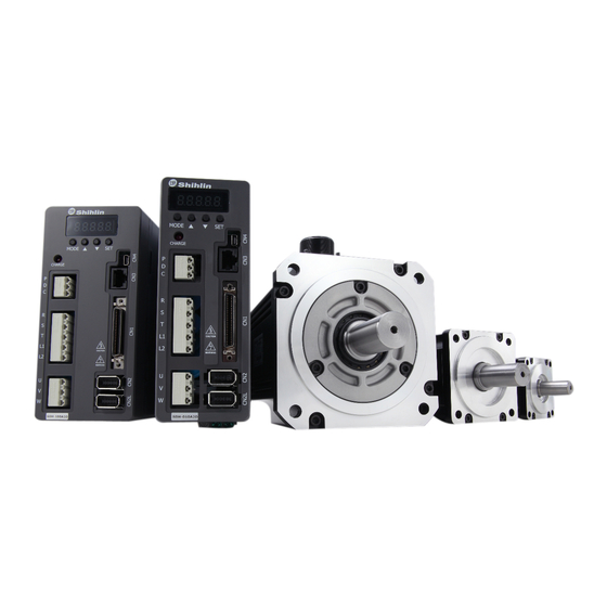
Chapter 1. 1.3 Servo drive apperance and panel description Display: A 5-digit LED matrix to show the alarm,status,parameters,etc. Operation: To switch the function of control m o d e , m o n i t o r p a r a m e t e r s adjustment. -
Page 13: Overview Of Servo Drive Operation Modes
♦ If the default value of PA01 is applied, set the PA01 value as “1□□□” . 1.5 Recommended specifications for circuit breaker and fuse Specification of circuit breaker and fuse are applicable to Shihlin Servo drives. Drive type Fuse capacity... -
Page 14: Installation
2.2 The environment conditions of installation The ambient temperature suitable for Shihlin drive is between 0 ℃ and 55 ℃ . If the ambient temperature is higher than 45 ℃ , The installation place with good ventilation or air conditioner is necessary. For a long-time operation, place the drive in an environment with temperature below 45 ℃... - Page 15 SDH Series Manual Installation diagram: To achieve a lower wind resistance of the heat-dissipation fan for a more effective heat removal, follow the spacing recommendation for installing one or multiple AD drive Servo Drive.See the figure below. 100m m (4.0 in.)
-
Page 16: Wiring And Signals
Chapter 3. 3. Wiring and signals This chapter defines the wiring diagrams for operation and the signals of Shihlin servo drive. 3.1 Connections between main power source and peripheral devices 3.1.1. Wiring diagram of peripheral devices-Below 1KW ※ The details of EMI filter, please refer to Section 11.1(EMI Filter) -
Page 17: Wiring Diagram Of Peripheral Devices(1.5Kw~3Kw)
SDH Series Manual 3.1.2 Wiring diagram of peripheral devices-above 1.5KW 3-phase 200~230V power supply Communication software Main circuit breaker (NFB) Host controller or PLC Magnectic contactor EMI filter R、 S、T Location feedback signal port (option ) CN2L L1、 L2 Make P/D open-circuit. -
Page 18: Wiring Diagram Of Peripheral Devices(Above 5Kw)
3.1.4 Wiring method of power source Shihlin servo drive is connected to a three-phase power source. In the figure below, Power ON is contact a and alarm processing is contact b. 1MC/a is the self-maintained power source, and 1MC is the electromagnetic contactor. -
Page 19: Wiring Method Of Power Source
SDH Series Manual 3.1.5 Lead wire connector specifications of motor U/V/W terminals Connector specifications (female type) of U/V/W terminals of the low inertia Shihlin servo motor: Drive capacity Motor type 100W SMH-L010R30S□□ 200W SMH-L020R30S□□ 400W SMH-L040R30S□□ 750W SMH-L075R30S□□ With brake... - Page 20 Chapter 3. 3.1.6 Selection of wiring materials Please follow the following recommendations and the use the proper specification. Specification for power wiring(AWG) Drive type Motor type U 、 V 、 W R 、 S 、 T L1 、 L2 P 、 D 、 C SDH-010A2 SMH-L010R30S□□...
-
Page 21: Functional Block Diagram Of Shihlin Servo
SDH Series Manual 3.2 Functional block diagram of Shihlin servo 100W~1kW: Shihlin servo driver Power source: 100W~15KW, 3Φ200~230Vac... - Page 22 Chapter 3. 100W~1kW: Shihlin servo driver Power source: 100W~15KW, 3Φ200~230Vac...
-
Page 23: Cn1 I/O Signal Wires Instruction
3.3.1 CN1terminal layout Shihlin servo drive provides 12 sets of DI inputs and 6 sets of DO outputs for users to program,which makes the application with the host controller more flexible. The 12 input DI parameters for users are PD02 to PD09,and PD21 to PD24.And the 6 output DO parameters are PD10 to PD14 and PD26.In addition, it affords encoders encoder differential... - Page 24 Chapter 3. Pin name Signal name No Pin name Signal name +15power supply output(analog Vcc(15V) +15power supply output(analog command) Vcc(15V) command) VC/VLA Speed analog command/limit TC/TLA Torque analog command/limit High forward/revere rotation pulse Signal ground of analog input/output train(4Mpps) High forward/revere rotation pulse Signal ground of analog input train(4Mpps) Forward/reverse rotation pulse train...
-
Page 25: Signal Description Of Cn1 Terminal
SDH Series Manual 3.3.2 Signal description of CN1 terminal Signals listed in aforesaid section will be described in detail in this section. 1. CN1 terminal signal description There are 50 Pins on CN1 terminal. Every pin function would be described as below: The abbreviation for the control modes in the table below are explained as below: Pt :... - Page 26 Chapter 3. Signal name Sign Pin NO Function description Control mode As signals in open collector type; this pin provides DC24V is Open collector power CN1-7 the ground CN1-24 Signal ground of The common ground of SON,EMG digital input. Each pin CN1-25 digital I/O inside the drive is connected together but separated from LC.
- Page 27 SDH Series Manual Below is D/I and D/O signal description 2.I/O signal description of CN1 terminal Some signals and their abbreviation reference table for the I/O signals of CN1 are presented below: Abbr. Signal name Abbr. Signal name Servo ON...
- Page 28 Chapter 3. 3.DI and DO signal description Input DI There are 39 signal functions could be assigned to the particular DI pin by the modification of parameter. As the below sheet: Control Signal function Sign Factions/Applications description mode Power on the drive and make SON short-circuit to ready (the shaft is locked). Make SON open-circuit Servo ON to release (The shit is rotatable).
- Page 29 SDH Series Manual Forward rotation Used to start the servo motor in the following directions: activated Input signal Servo motor starting direction Stop(servo lock) Reverse rotation activated Stop(servo lock) If both ST1 and ST2 are switched ON or OFF during operation, the servo will be decelerated to a stop according to the value of PC18 and the motor will be locked.
- Page 30 Chapter 3. Position command POS1 option1 Position command POS2 Position option2 POS6 POS5 POS4 POS3 POS2 POS1 CTRG command Position ↑ command POS3 ↑ option3 Position command POS4 ↑ option4 ↑ Position command POS5 ↑ option5 Position command POS6 option6 Position In position control with inner 6 registers (Pr mode), the combination of POS1 command...
- Page 31 SDH Series Manual Output DO Every DO pin is programmable. There are 14 output function could be assigned to the particular DO pin by the modification as the function described below: Signal function Sign Function Control mode Ready It is ON as power is turned on a drive is ready to operate.
- Page 32 Chapter 3. DI value Sign Function Pt-S Pt-T Pr-S Pr-T 0x01 Servo ON 0x02 Reset 0x03 Proportion control 0x04 Torque limit option DI11 DI11 DI11 DI11 DI11 0x05 Inner torque limit option DI11 0x06 Speed option 1 DI11 DI11 0x07 Speed option 2 0x08 Speed option 3...
- Page 33 SDH Series Manual DO output function with commanded values Value Sign Function Pt-S Pt-T Pr-S Pr-T 0x01 Ready DO5 DO5 DO5 DO5 DO5 DO5 DO5 DO5 DO5 0x02 Trouble DO6 DO6 DO6 DO6 DO6 DO6 DO6 DO6 DO6 0x03 In-position ready...
-
Page 34: Interface Wiring Diagram
Chapter 3. 3.3.3 Interface wiring diagram (1) Digital input interface DI For use of inner power supply For use of external power supply (2) Source input interface When using the input interface of source type, all DI input signals are of source type. Source output could not be provided. - Page 35 SDH Series Manual (3) Digital output interface DO Lamp, Relay or photo coupler could be driven. A diode for relay load or a suppressing resistor for lamp load is necessary. (Permissible current: 40mA or less, inrush current: 100mA or less)
- Page 36 Chapter 3. Differential Line Drive type Differential Line Drive pulse with encoder Output pulse with output photo Coupler (6) Rotation pulse train input Input a pulse train signal in open collector or differential Line drive type. The maximum input pulse frequency is 500kpps for differential Line drive, the high-speed input pulse is 4Mpps and 200kpps for open collector type.
- Page 37 SDH Series Manual Differential (Line Drive) type High-speed input pulse, differential (Line Drive) type NOTE: This input system is 5V. Do not be used 24V.Note Suggest the controller connect with the signal ground of servo drive.
- Page 38 Chapter 3. 3.3.4 User definition of DI/DO signal The DI/DO default functions are suitable for position mode. If they are not suitable for user’s application, please define the functions of DI/DO AGAIN. The functions of DI1to DI12 are corresponding to the setting of parameters PD-02 to PD- 09.
-
Page 39: Cn2 Encoder Signal Wiring And Description
SDH Series Manual 3.4 CN2 Encoder signal wiring and description The resolution of Shihlin servo motor encoder is 22-bit. The appearance of CN2 connector is shown below: (1)CN2 connector (Female type) 3M connector back view (2)CN2 connector (Meal type) Connector side view Molex connector back view Table 1-3-2... -
Page 40: Cn2L Encoder
Chapter 3. The appearance of encoder cable connector of Shihlin medium inertia servo motor is shown below: Motor side:Male connector The suitable Shihlin servo drive capacity of connector is shown below: Drive Capacity Motor type 500W SMH-M050R20A□□ SMH-M100R20A□□ 1.5KW SMH-M150R20A□□... -
Page 41: Cn3 Communication Port Signal Wiring And Description
3.7 CN4 USB communication port For the plug-and-play usage, Shihlin servo drive provides the USB port (CN4). Similar to RS232 and RS485 of CN3, CN4 in Mini-USB type, users could connect it to the computer then set parameters, monitor the status, operate and test, etc. -
Page 42: Wiring Diagram Of Position Control(Pr Mode)
Chapter 3. 3.8.1 Wiring diagram of position control(Pr Mode) Servo driver MCCB Brake resistor (*2) 3Φ,AC200~230V Servo motor 2.5KΩ 5KΩ 3, 4, 31 50m or less (*1) COM+ 47, 49 ENCP ENCN POS1 POS2 CTRG Encoder A line driver POS3 Encoder B line driver POS4 DI11... -
Page 43: Wiring Diagram Of Position Control(Pt Mode)
SDH Series Manual 3.8.2 Wiring diagram of position control(Pt Mode) Note 1.If the external power is applied, do not connect +24Vdd and COM+. 2.See section 3.1.3 for the wirings of brake resistor. -
Page 44: Wiring Diagram Of Speed Control(S Mode)
Chapter 3. 3.8.3 Wiring diagram of speed control(S Mode) Note 1.If the external power is applied, do not connect +24Vdd and COM+. 2.See section 3.1.3 for the wirings of brake resistor. -
Page 45: Wiring Diagram Of Torque Control(T Mode)
SDH Series Manual 3.8.4 Wiring diagram of torque control(T Mode) Servo driver MCCB Brake resistor (*2) 3Φ ,AC200~230V 2.5KΩ Servo motor 5KΩ 3, 4, 31 2.5KΩ 50m or less 5KΩ 3, 4, 31 ENCP ENCN (*1) COM+ 47, 49 Encoder A line driver... -
Page 46: Wiring Diagram With 1Pg
Chapter 3. 3.8.5 Wiring diagram with 1PG A(F)X2N PLC Servo driver MC MCCB 3Φ,AC200~230V Brake resistor(*) Error reset Servo motor Stop Forward limit Reverse limit JOG+ JOG- Home position Encoder Start Ready Position completed Servo failure Extended cable A(F)X2N-1PG Stop COM+ 47、49 STOP... -
Page 47: Wiring Diagram With 10Pg
SDH Series Manual 3.8.6 Wiring diagram with 10PG A(F)X2N PLC Servo driver MC MCCB 3Φ,AC200~230V Stop Brake resistor(*) Error reset Home position Servo motor Forward limit Reverse limit JOG+ JOG- External command Encoder M code OFF Extended cable A(F)X2N-10PG START... -
Page 48: Wiring Diagram With 10Gm
Chapter 3. 3.8.7 Wiring diagram with 10GM A(F)X2N-10GM Servo driver CON1 MC MCCB COM1 3Φ,AC200~230V Start START Stop STOP Home position Manual FWD Manual REV Brake resistor(*) FWD limit Servo motor REV limit CON1 COM1 General input Encoder COM1 DC 5~24V 47、49 COM+ General putput CON2... -
Page 49: Wiring Diagram With 20Gm
SDH Series Manual 3.8.8 Wiring diagram with 20GM A(F)X2N-20GM CON2 COM1 Servo driver Start START Stop STOP MC MCCB Home position 3Φ,AC200~230V Manual FWD Manual REV FWD limit Brake resistor(*) REV limit CON1 Servo motor COM1 General input Encoder +24Vdd 47、49... -
Page 50: Wiring Diagram With Fx3U
Chapter 3. 3.8.9 Wiring diagram with FX3 FX3U-32MT/ES Servo driver AC100V~240V MC MCCB 3Φ ,AC200~230V Brake resistor(*) Servo motor PIN4 (RD) 24、25、50 Encoder 24、25、50 COM1 +24Vdd 47、49 COM+ 24、25、50 COM2 FX2N-16EYT COM1 24、25、50 Shield FX2N-16EX- 24、25、50 ES/UL 10m or less Instant stop +24Vdd Home position... -
Page 51: Wiring Diagram With Qd75
SDH Series Manual 3.8.10 Wiring diagram with QD75 Servo driver QD75P MC MCCB 3Φ,AC200~230V PULSE F PULSE COM PULSE R PULSE COM Brake resistor(*) QD75D Servo motor DC 24V H limit signal L limit signal Encoder Stop STOP External signal... -
Page 52: Wiring Diagram With Gantry
Chapter 3. 3.8.11 Wiring diagram with Gantry... -
Page 53: Panel Display And Operation
This display with 7-segment LED of 5 digits, is used to monitor the states of servo and the LED display value of parameters, and set modification value. To switch one display mode to the others. Shihlin servo drive has parameter display mode, MODE key alarm history mode, status monitor mode, etc.This button becomes to “Shift “function when in parameter writing-in mode. -
Page 54: Status Display
Chapter 4. 4.3 Status display The operation status of Shihlin servo could be displayed on the 5-digit 7 segment LED display. Press the “UP” or “DOWN” key to change the display data as desired. When the required data is selected, the corresponding symbol appears. Press the “SET” key to display the information. - Page 55 SDH Series Manual List of status display The servo statuses which may be shown are listed in the following table Status display Sign unit Description Range Motor feedback pulses Motor feedback pulses (High digit) (High digit) FPH.I pulse (before electric gear ratio)
- Page 56 Chapter 4. Position control mode, speed control mode: 0~ 300 Torque input limit is displayed in percentage. Torque input command/limit (2) Torque control mode: -300~300 Torque command is displayed in percentage. The continuous and effective load torque is displayed Effective load ratio 0~ 300 relative to the rated torque of 100%.
-
Page 57: Alarm Display
SDH Series Manual 4.4 Alarm display It displays the current alarm and the alarm history record. The lower two digits display the abnormal alarm number which has occurred. Name Display Description No alarm occurred. Current alarm Over voltage occurred(AL 01), The screen flickers synchronously. -
Page 58: Diagnostic Display
Chapter 4. 4.5 Diagnostic display The following table provides information related to the operation of diagnostic display: Name Display Description Not ready yet. The drive is being initialized, an alarm has occurred or SON pin is OFF Control status Ready. Initialization completed;... -
Page 59: Do Forced Output
SDH Series Manual (2) The display of I/O pin definition Suitable for 7-segment LED position and PIN. The 7-segment LED shown above indicates the ON/OFF states of DI and DO. The top segments indicate the input signals(DI1~DI10) which are ON and the bottom segments indicate the output signal(DO1~DO6 、... -
Page 60: Jog Test
Chapter 4. 4.5.3 JOG test mode As neither external command nor any alarm occurred, JOG test could be executed. Do not execute this operation until the contact between SON and SG is open. Set the speed command of JOG by the PC04, set the acceleration time by the PC01, and set the deceleration time by the PC02. -
Page 61: Positioning Test
SDH Series Manual 4.5.4 Positioning test Shihlin communication software which needs to be connected by RS-232 or USB is required to execute the positioning test. As no external command nor any alarm occurred, positioning test could be executed.Before this operation, make sure that the contact between SON and SG is open. -
Page 62: Automatic Offset Of Analog Command Input
Chapter 4. 4.5.5 Automatic offset of analog command input When the external speed analog command input is 0V, there may be still an offset voltage which will cause a slow motor rotation inside the servo drive. The user could “erase” this bias with the automatic offset function in the diagnostic display mode. -
Page 63: Inertia Estimation
SDH Series Manual 4.5.6 Inertia estimation Shihlin communication software which needs to be connected by RS-232 or USB is required to execute the positioning test. As no external command nor any alarm occurred, positioning test could be executed. Operation Make sure that the motor is wired correctly before operating this inertia estimation. Under Shihlin communication window, choose the “auto gain tuning”... -
Page 64: 32Bit Parameter Setting Method
Chapter 4. Press the “UP DOWN “button to the next parameter. When changing the parameter PH 01, it is required to restart the power after changing the value to complete this setting. Switch the usage of “MODE” key to the “shift” function when parameter setting. The Use of "MODE"... - Page 65 SDH Series Manual Decimal parameter display data (Negative value) Example: PA19 = 1234567 and change the parameter to -1234567, the setting method show below.
- Page 66 Chapter 4. Hexadecimal parameter display data Example: PE01 = 0x03760135, and change the parameter to 0x03740135, the setting method show below.
- Page 67 SDH Series Manual Parameter data display example Display Item Description 7-segment LED Hexadecimal display If the value is 0x1234, the display is 1234. Decimal Positive value display If the value is 2500, the display is 2500 data Decimal Negative value display If the value is -12566, the display is 1.2.5.6.6.
-
Page 68: Operation
To confirm an open contact between SON and SG before this operation. The idle JOG test could be executed with the drive’s panel or Shihlin communication software in order to check if the speed and direction of the motor is as expected or not. The motor speed could not be modified with the drive’s panel. If the rotation speed has to be modified, please use Shihlin communication software which is connected by RS-232 or USB to modify. -
Page 69: Idle Positioning Test
Step 4. To terminate the idle JOG test, turn off the power or press the “SET” key more than 2 seconds in the display of “d-01” screen. • If Shihlin communication software is applied to perform the idle JOG test, please refer to the instruction of the help file for more detail. 5.2.2 Idle positioning test The idle positioning test could be executed with Shihlin communication software connected by RS-232or USB to check if the speed and direction of the motor is as expected. -
Page 70: Tuning Process
Chapter 5. 5.3 Tuning process • Please do not adjust and change parameters extremely which will cause device instability. CAUTION 5.3.1 Abstract With the auto-gain tuning function, the mechanical load inertia could be approximated precisely. The appropriate gain value of controller parameter also could be fitted for the servo motor under the various load conditions. The manual tuning function is executed as the result of auto-gain tuning function is not suitable for the user’s mechanical system. -
Page 71: Auto-Gain Tuning Mode
SDH Series Manual 5.3.2 Auto-gain tuning mode The auto-gain tuning of the drive could calculate the ratio of load inertia to motor shaft instantaneously. With this value, the optimum gain could be decided under the current mechanical condition. It is convenient to execute the adjustment of gain value with the auto-gain tuning function. - Page 72 Chapter 5. 5.3.2.2 The flow of auto-gain tuning mode The flow of auto-gain tuning mode for the servo drive could be presented below: When the auto-gain tuning mode is performed, the following conditions should be satisfied. As the mode 1 operated, at first execute the acceleration/deceleration routes of the motor, the ratio of load inertia to motor shaft would be approximated according to the current and speed.
- Page 73 SDH Series Manual Since the auto-gain tuning mode 1 is made valid as the default from the factory, simply running the acceleration/ deceleration route of the motor would automatically obtain the optimum gains that match the machine. Merely changing the response level setting value as required completes the adjustment. The adjustment procedure is as follows.
-
Page 74: Manual Gain Tuning Mode
Chapter 5. Speed loop Speed loop Response level Response level Machine rigidity response Machine rigidity response setting setting frequency (Hz) frequency (Hz) 10.0 67.1 11.3 75.6 Middle 12.7 85.2 14.3 95.9 16.1 108.0 18.1 121.7 20.4 137.1 23.0 154.4 25.9 173.9 29.2 195.9... - Page 75 SDH Series Manual ► Position loop gain (PG1) This parameter determines the response level of the position loop. Increasing PG1 improves traceability, settling time and position error to a position command but a too high value will make overshooting or vibration to occur. Its formula is as follows: PG1 setting value ≤...
-
Page 76: Parameter Setting And Operation For Position Control Mode
Chapter 5. 5.4 Parameter setting and operation for position control mode (1) Power on To switch off the SON signal of DI after the servo drive has turned on. The panel of the drive would show “Servo motor rotation speed”2 second latter. (2) Test operation Confirm the state of the servo motor with the JOG test. -
Page 77: Parameter Setting And Operation For Speed Control Mode
SDH Series Manual 5.5 Parameter setting and operation for speed control mode (1) Power on To switch off the SON signal of DI after the servo drive has turned on. The panel of the drive would show“Servo motor rotation speed”2 second latter (2) Test operation Check if the state of the servo motor normal or not with the JOG test. -
Page 78: Parameter Setting And Operation For Torque Control Mode
Chapter 5. (c)EMG OFF The same actions as above but the ALM message is displayed (d)LSP/LSN signal off : LSP on is rotatable in CCW. LSN on is rotatable in CW. If it is off, the dynamic brake works. (f)If ST1 and ST2 are both on or both off, the motor would decelerate to stop. 5.6 Parameter setting and operation for torque control mode (1) Power on To switch off the SON signal of DI after the servo drive has turned on. -
Page 79: Control Function
6.1 Control mode option The are 4 basic operation modes for Shihlin servo drive: position control with terminals input, position control with inner registers, speed control, torque control. The drive could be operated in single mode or hybrid mode. All operation modes are described as below. -
Page 80: Torque Analog Command Offset
Chapter 6. 6.2.2 Torque analog command offset When the torque analog command input is 0V, there may be still an offset voltage which will cause a slow motor rotation. In such case, the user could use the parameter PC27 to correct the bias voltage.The parameter description is as follows. -
Page 81: Torque Limit Of Torque Control Mode
SDH Series Manual 6.2.4 Torque limit of torque control mode The parameter PA05 and PC25 are used to limit the generated torque of the servo motor when the torque control mode is performed. The description is as follows. Name Abbr. -
Page 82: Speed Control Mode
6.3.1 Selection of speed command Shihlin servo have two types of speed command , one is setting 7 speed command by internal parameters; the other is external inputs ± 10V analog voltage commands,There are 8 combinations which are listed below for user to choose. -
Page 83: Output Speed Of Maximum Speed Analog Command
SDH Series Manual Valid Related Speed command Setting range option parameter Speed Analog Command ±10V PC 12 (VC) Inner speed command 1 -4500 ~ 4500 PC 05 Inner speed command 2 -4500 ~ 4500 PC 06 SP3 is valid Inner speed command 3... - Page 84 Chapter 6. The 3 parameters will be described in detail as follows. Acceleration time constant : This parameter is the time spent for the motor from 0 rpm to the rated speed and it is defined as “acceleration time constant”. For example, if the rated speed of the servo motor is 3000 rpm and this parameter is set as 3000 (3s). In such case, the motor accelerating from 0 rpm to 3000 rpm would take 3 seconds.
-
Page 85: Torque Limit Of Speed Control Mode
SDH Series Manual Low-pass filter smooth time constant : Name Abbr. Sign Setting range Unit Initial value Control mode Speed low-pass filter smooth SFLT PB 18 0~1000 S 、 T time constant[mS] A larger parameter value would soothe the speed command more obviously. However, the response would slow down as well. -
Page 86: Adjustment Of Speed Loop Gain
Chapter 6. 6.3.5 Adjustment of speed loop gain There are some parameters related to inner speed control loop for users to adjust. Set the value of the PA02 to use the auto-gain tuning function or manual-gain tuning function. If auto-gain tuning function is performed, the load inertia ratio would be approximated continuously and the control gain value would be set automatically. - Page 87 When the mechanism with low rigidity generates resonance by reason of the large bandwidth or the large rigidity setting value of the servo drive. If the mechanism factors could not be adjusted, Shihlin servo drive provides 3 resonance filter frequencies and 1 resonance suppression low-pass filter for users to make adjustment. Some parameters related to resonance suppression filter are introduced below.
- Page 88 Chapter 6. (2)Auto low frequency resonance suppression functio n: When the command changes instantly due to lack of rigidity makes the transmission side and the load side of the motor cannot be synchronized will cause mechanical vibration, influence position accurate and defect-free rate for product.
- Page 89 SDH Series Manual ►Auto suppression method : There are two sets of auto resonance suppression filter for users to operate auto low frequency resonant sup- pression which one is PB31 and PB32, the second one is PB33 and PB34; PB21 、 PB25 are suppression frequencies;...
-
Page 90: Gain Switch Function
Chapter 6. 6.3.7 Gain switch function The gain switch could be performed for the drive during the running or stop status of the motor. The programmable DI pins could be set as the function of gain switch. If this function is applied, the gain tuning mode option (PA02) should be set as ”□□□0”... - Page 91 SDH Series Manual (5) The ratio 2 of load inertia to motor shaft GD2 (PB14) Enable to set to change the ratio of load inertia to motor shaft and if the ratio of load inertia to motor shaft does not change, please set this parameter to the value of GD1 (PB06).
-
Page 92: Position Control Mode
Chapter 6. Example 2: Trigger condition of position command pulse error. Relevant parameters setting: Name Name Sign Setting value Unit Abbr. The ratio of load inertia to motor shaft PB 06 0.1time Position loop gain PB07 rad/s Speed loop gain PB08 rad/s Speed integral gain... -
Page 93: External Pulse-Train Command(Pt Mode)
SDH Series Manual ►The S-pattern smooth is invalid as the external pulse-train commands are applied. 6.4.1 External pulse-train command (Pt Command) Setting Initial Control Name Name Abbr. Sign unit Description range value mode Setting external pulse-train command x:Setting value of Control mode option:... -
Page 94: Inner Register Command(Pr Mode)
Chapter 6. A/B phase pulse train pulse train + sign Forward/reverse rotation pulse train If pulse train is line drive type, the highest permissible frequency is 500Kpps. If pulse train is open collector type, the highest permissible frequency is 200Kpps. 6.4.2 Inner register command (Pr Command) Please refer to chapter 7 for details. -
Page 95: Position Command Smoothing
SDH Series Manual For example, enter the position register P1 and P2 to 30 turns and 60 turns, send P1 commands and then send P2 command. The results of absolute and incremental type even the same sequent of commands are listed. -
Page 96: Electronic Gear Ratio
Chapter 6. As a forward/reverse rotation due to position command is done, the acceleration/deceleration time is decided by the PF49~PF64. As the inner register command is applied, it is recommended to use the S-pattern smoothing. Note: The setting of ACC and DEC, please refer to the chapter 7. 6.4.4 Electronic gear ratio Users could set different electronic gear ratios to enable the transmission mechanism to move different distances. -
Page 97: Torque Limit Of Position Control Mode
SDH Series Manual 4 electronic gear numerators are available for users to select. Enable the function CM1 and CM2 of DI to switch. See the table below. Name Control mode Electronic gear numerator 1 (PA 06) Pt、Pr Electronic gear numerator 2 (PC 32) Pt、Pr... -
Page 98: Hybrid Control Mode
Chapter 6. Parameters related to position gain adjustment are listed below. Name Name Abbr. Sign Setting range Unit Initial value Control mode Gain tuning mode option ATUM PA02 0000h~0003h 0002h Pt、Pr、S、T Auto-tuning response level setting ATUL PA03 1~32 Pt、Pr、S、T Position feed-forward gain PB05 0~200 Pt、Pr... -
Page 99: Position/Speed Hybrid Mode
SDH Series Manual 6.5.1 Position/speed hybrid mode This hybrid mode is divided into 2 types in detail. i.e. Pt/S and Pr/S. The sequence chart of mode switch is presented in the figure below. Control mode could not be switched if the motor is at a high speed rotation. It could be performed as the zero speed detection output a signal is ON. -
Page 100: Torque/Position Hybrid Mode
Chapter 6. 6.5.3 Torque/Position hybrid mode This hybrid mode is divided into 2 types in detail. i.e. T/Pt and T/Pr. Users could set the PA01 as 1005(T/Pt mode) or 1015(T/Pr mode). The switch could not be performed if the motor is at a high speed rotation. It could be switched as the zero speed detection output signal is ON. -
Page 101: Other Functions
P-D terminals is short-circuit. If the external brake resistor applied, make P/D terminals open while the external resistor is connected to the P/C terminals. Built-in brake resistor specifications for Shihlin servo drive are described below. Built-in brake resistor specification Consumption power of built-in Drive (W) Minimum permissible (Ω) - Page 102 Chapter 6. The capacity of brake resistor is calculated as follows: Power of brake resistor (Pbr) ==> N is the ratio of load inertia to motor shaft. T is duty cycle (Defined by users). If the ratio of load inertia to motor shaft is N, deceleration from 3000rpm to stop; the regenerative energy is (N +1) ×...
-
Page 103: Analog Monitor Output
SDH Series Manual Power of the external load torque( PL)=TL × ω Where: TL : is the external load torque. (Unit: Nt-m) ω : is the motor rotation speed. (Unit: rad/s) Please calculate this value at safe condition as possible as you can. -
Page 104: Operation Of Electromagnetic Brake Interlock
Chapter 6. Name Setting Initial Control Name Sign Description Unit Abbr. range value mode -999 Used to set the offset voltage of Analog monitor MO1 offset PC 28 the analog monitor MO 1 output. -999 Used to set the offset voltage of Analog monitor MO2 offset PC 29 the analog monitor MO 2 output. - Page 105 SDH Series Manual The operation sequence of electromagnetic brake is plotted below. Wiring diagram of electromagnetic brake (MBR DO applied) Attention Specification of electromagnetic brake: SMA series Motor type L010B L020B/L040B L075B M050B/M100B/M150B M200B/M350B Brake type Spring brake (Normal locked)
-
Page 106: Pr (Procedure) Procedure Control Function Description
Chapter 7. 7. PR (Procedure) Procedure control function description 7.1 Pr mode description PR (Procedure): PR Procedure is the minimum unit of command in PR mode. A command is composed by one procedure or many procedures and there are 64 sets of procedure which are plan able consist of one home returning procedure and 63 sets PR procedure. -
Page 107: Parameter Setting Of Pr Mode
SDH Series Manual Command trigger description of PR mode : Command source Description The usage of DI: POS1~6 assigned procedure NO. which wants to be triggered Standard and then trigger PR command with the rising edge of DI: CTRG. triggering CTRG↑+POS1~6... - Page 108 Chapter 7. The path format and function is determined by TYPE. Here is the definition : TYPE=1 means constant speed control; TYPE=2 means in-position control; TYPE=3 means AUTO in-position control; TYPE=7 means procedure jump; TYPE=8 means parameter write in; TYPE=A means index position control. Although TYPE=2 and TYPE=3 all mean in-position control, but the difference of them is that TYPE=3 could operate next proce- dure automatically.
- Page 109 SDH Series Manual SPD: The range of value is 0~F. Enable to set target speed NO. The definition is shown below. SPD Value … Corresponding PF48 PF47 PF46 PF45 PF44 … PF37 PF36 PF35 PF34 PF33 parameter DLY: The range of value is 0~F. Enable to set delay time NO.
- Page 110 Chapter 7. SOUR: The setting of data source. There are two types of data source setting, one is ‘constant write in’ and the other is ‘parameter value write in’. SOUR option Description Bit 27 Bit 26 (SOUR) Bit 25 Bit 24 Data source Writing purpose Constant...
- Page 111 SDH Series Manual S_LOW: The selection of speed unit: Bit 24=0 means the speed unit is 0.1 rpm; Bit 24=1 means the speed unit is 0.01 rpm. AUTO: When the path completed, load to next path automatically. DATA: Enable to set the coordinate value of each index positioning.
-
Page 112: The Status Of Procedure Connection
Chapter 7. If PATH=0, the position will not move to origin point. If PATH=A, the position will move to origin point and run PR#A automatically. Please set PR#A as absolute command of positioning control and let command =ORG_DEF. There is no definition of offset about home return, where rather using the PATH to be specified as an offset value of a path. - Page 113 SDH Series Manual PR#12(AUTO speed control 、 target speed:2000 rpm 、 delay time: 200 ms) → PR#13(position control 、 absolute position : 0 pulse) As shown as the following chart that it is a typical sequence command for the situation of constant speed control continuous positioning control.
- Page 114 Chapter 7. PR#12(AUTO position control 、 incremental position stroke: 10485760 pulse 、 target speed: 600 rpm 、 delay time: 1500 ms 、 ACC: 200 ms 、 DEC: 200 ms) → PR#13( position control 、 Insert 、 incremental position stroke: -10485760 pulse 、 target speed: 600 rpm 、...
-
Page 115: Parameters
SDH Series Manual 8. Parameters 8.1 Parameter definition SDH servo drive’s parameters are classified into the basic, gain values, filters, expansion and I/O group according to safety aspects and frequencies of use. When an advance adjustment is required, change the PA42 setting to make the expansion parameters write-enabled. -
Page 116: Parameter List
8.2 Parameter list The parameters of Shihlin servo drive could be classify into 5 groups. PA group is basic for control mode option, auto-tuning, etc. PB group is for gain and filter functions which enables to tune servo motor in stable operation. PC group is expansion parameter which is related to speed/torque control and analog signal and communication functions. - Page 117 SDH Series Manual (2) Gain, filter parameters Control Mode Abbr. Name Initial Value Unit PB01 NHF1 Machine resonance suppression filter 1 1000 ○ ○ ○ ○ PB02 NHD1 Machine resonance suppression attenuation 1 ○ ○ ○ ○ PB03 Resonance suppression low-pass filter 0.1mS...
- Page 118 Chapter 8. (3) Expansion parameters Control Mode Abbr. Name Initial Value Unit PC01 STA Acceleration time constant ○ ○ ○ PC02 STB Deceleration time constant ○ ○ ○ PC03 STC S-pattern acc./dec. time constant ○ ○ ○ PC04 JOG JOG speed command ○...
- Page 119 SDH Series Manual (4) I/O setting parameters Control Mode Abbr. Name Initial Value Unit PD01( ★ ) DIA1 Digital input signal auto-ON option 1 0000h ○ ○ ○ ○ PD02( ★ ) Digital input 1 option 0001h ○ ○ ○...
- Page 120 Chapter 8. (5) Pr position path planning parameter group 1 Control Mode Abbr. Name Initial Value Unit PE01 ODEF Origin return Definition 00000000h ○ PE02 ODAT Origin Data value ○ PE03 PDEF1 PATH#1 Definition 00000000h ○ PE04 PDAT1 PATH#1 Data ○...
- Page 121 SDH Series Manual PE58 PDAT28 PATH#28 Data ○ PE59 PDEF29 PATH#29 Definition 00000000h ○ PE60 PDAT29 PATH#29 Data ○ PE61 PDEF30 PATH#30 Definition 00000000h ○ PE62 PDAT30 PATH#30 Data ○ PE63 PDEF31 PATH#31 Definition 00000000h ○ PE64 PDAT31 PATH#31 Data ○...
- Page 122 Chapter 8. (6)Pr position path planning parameter group 2 Control Mode Abbr. Name Initial Value Unit PF01 PDEF49 PATH#49 Definition 00000000h ○ PF02 PDAT49 PATH#49 Data ○ PF03 PDEF50 PATH#50 Definition 00000000h ○ PF04 PDAT50 PATH#50 Data ○ PF05 PDEF51 PATH#51 Definition 00000000h ○...
- Page 123 SDH Series Manual Acceleration and deceleration time of internal PF54 POA6 ○ position command 6 Acceleration and deceleration time of internal PF55 POA7 1000 ○ position command 7 Acceleration and deceleration time of internal PF56 POA8 1200 ○ position command 8...
- Page 124 Chapter 8. The following table including the relevant parameters with different modes is helpful for users convenient to consult. Torque control related parameters Control Mode Abbr. Name Initial Value Unit PA01(*) STY Control mode setting value 1000h ○ ○ ○ ○...
- Page 125 SDH Series Manual Smoothing filter and resonance suppression related parameters Control Mode Abbr. Name Initial Value Unit PB01 NHF1 Machine resonance suppression filter 1 1000 ○ ○ ○ ○ PB02 NHD1 Machine resonance suppression attenuation 1 ○ ○ ○ ○...
- Page 126 Chapter 8. PD05(*) DI4 Digital input 4 option(CN1-17) 0004h ○ ○ ○ ○ PD06(*) DI5 Digital input 5 option(CN1-18) 0002h ○ ○ ○ ○ PD07(*) DI6 Digital input 6 option(CN1-19) 000Fh ○ ○ ○ ○ PD08(*) DI7 Digital input 7 option(CN1-20) 0012h ○...
-
Page 127: Parameter Details List
SDH Series Manual 8.3 Parameter details Control Initial Setting Abbr. Function description unit Mode Value range Setting value of Control mode option: x:control mode select 0:position 1:position/speed 2:speed 3:speed/torque 4:torque 5:torque/position 0000h y:position command select Pr.Pt PA01 1000h 0 : external input... - Page 128 Chapter 8. Control Initial Setting Abbr. Function description unit Mode Value range Home moving option: Limit setting Z signal setting Home moving option x=0: Home return in CW rotation, LSP is origin. x=1: Home return in CCW y=0 : motor turns back to last Z rotation,LSN is origin.
- Page 129 SDH Series Manual PA06 CMX Electronic gear numerator Pr. Pt Electronic gear denominator The improper setting could lead to unexpected fast rotation so make sure to set them in the state of SERVO OFF. The proper range setting is: Pulse command input...
- Page 130 Chapter 8. Control Initial Setting Abbr. Function description unit Mode Value range Pulse command option : Setting value of Control mode option: x : pulse-train format select x=0 : forward/reverse rotation pulse train , x=1 : pulse train + sign x=2 :...
- Page 131 SDH Series Manual Control Initial Setting Abbr. Function description unit Mode Value range Motor crash protection level (percentage) Pr.Pt Used to prevent the motor running from crashing the mechanical PA15 CRSHA 0~300 equipment. If PA15 is 0, the function is disabled. Any non-zero value setting will enable this function.
- Page 132 Chapter 8. Absolute encoder settings Used to permit that the motor with absolute encoder but is operated as an incremental motor. 0000h Pr.Pt PA28 0: Incremental mode. 0000h 1: Absolute mode. 0001h This setting is only available for the servo motor with absolute encoder, otherwise the AL24 will occur.- Absolute homing position 0000h...
- Page 133 SDH Series Manual Motor rotary direction option The relation among motor rotary direction and input command pulse-train direction and encoder output pulse direction is described below. x : input pulse-train and motor rotary direction option motor rotary direction forward pulse-train...
- Page 134 Chapter 8. Control Initial Setting Abbr. Function description unit Mode Value range Electronic gear ratio mode 0 : normal, ratio=PA06/PA07 1 : ratio conversion 1, ratio= encoder resolution/ PA45 2 : ratio conversion 2, ratio= 2 x PA06/PA07, it is suitable for 22bit to 23bit conversion Here is a explanation diagram :...
- Page 135 SDH Series Manual Control Initial Setting Abbr. Function description unit Mode Value range The ratio of load inertia to motor shaft (load inertia ratio) Pr. Pt. PB06 GD1 Set the load inertia ratio value on the servo motor. When the auto tuning 0.1time...
- Page 136 Chapter 8. Control Initial Setting Abbr. Function description unit Mode Value range Torque command filter time constant : Larger value would make the response slow down obviously. If it is set as zero, this function is disabled. PB19 TQC 5000 The required time to catch the command is 5-time of TQC.
- Page 137 SDH Series Manual Low-frequency vibration suppression gain 2 The second low-frequency vibration suppression gain. The bigger value PB34 VSG2 it is, the better the position response will be. However, if the value is set Pr.Pt too big, the motor will not be able to smoothly operate. It is suggested to set the value to 1.
- Page 138 Chapter 8. Control Initial Setting Abbr. Function description unit Mode Value range Acceleration time constant This parameter is the time spent for the motor from 0 rpm to the rated speed and it is defined as “acceleration time constant”. For example, if the rated speed of the servo motor is 3000 rpm and this parameter is set as 3000 (3s).
- Page 139 SDH Series Manual Control Initial Setting Abbr. Function description unit Mode Value range Inner speed command/limit 5 -4500 For speed control, PC09 is used as inner speed command 5. PC09 SC5 For torque control, PC09 is the speed limit and directionless.
- Page 140 Chapter 8. Stop option and power interruption restart option x : power interruption restart option The voltage level drop would cause drive to alarm and stop. Auto- 0000h restart function could be applied by the setting of PC18. COP1 Pr.Pt PC18 0010h 0 : invalid...
- Page 141 SDH Series Manual Control Initial Setting Abbr. Function description unit Mode Value range Status display option : x : display option after power on (Hexadecimal) x=0 : Motor feedback pulse (High byte) (before electronic gear ratio) x=1 : Motor feedback revolution (Low byte) (before electronic gear ratio) x=2 :...
- Page 142 Chapter 8. Analog monitor ch2 offset -999 Pr.Pt PC29 Used to set the output offset voltage of analog monitor MON 2. See section 6.6.2 for more details. Analog monitor ch1 output proportion Pr.Pt PC30 MOG1 Used to set output ratio of monitor signal to be viewed. 0~100 See section 6.6.2 for more details.
- Page 143 SDH Series Manual 0000h Pr.Pt PD09 Digital input 8 option 0011h 002Fh Digital output 1 option 0000h The 6 DO output pins of CN1 are programmable. The preset pin Pr.Pt PD10 0003h functions are different corresponding to varied control modes. See 001Fh section 3.3.2 for more details...
- Page 144 Chapter 8. Alarm code output option x : output option 0 : output definition according to PD10 ~ PD14 1: to show alarm codes while alarms occurred ; see section 10.1 for detail Pin Content Setting value x CN1-41 CN1-42 CN1-45 By function By function...
- Page 145 SDH Series Manual Digital input status Digital input contacts (total of 12 points) are determined by the setting methods of digital. The digital input status of PD25 that bit 0 ~ 11 corresponds to DI1~DI12 at the time of communication control.
- Page 146 Chapter 8. Control Initial Setting Abbr. Function description unit Mode Value range Digital output 6 option 0000h The 6 DO output pins of CN1 are programmable. The preset pin Pr.Pt PD26 0002h functions are different corresponding to varied control modes. 001Fh See section 3.3.2 for more details.
- Page 147 SDH Series Manual Control Setting Abbr. Function description Initial Value unit Mode range 00000000h Home return definition PE01 PDEF1 00000000h Detail parameter definition as followings: 10FFFF3Fh 31~28 27~24 23~20 19~16 15~12 11~8 7~0 bit BOOT − − DEC1 ACC PATH PATH: path type (bit0~bit7) 0: Stop: Finish home returning and stop.
- Page 148 Chapter 8. Abbr. Function description Control Mode Initial Value Setting range unit PATH#1 definition 00000000h Detail definition as following. 00000000h See the chapter 7 for details of PR mode. FFFFFFFFh 31~28 27~24 23~20 19~16 15~12 11~8 3~0 bit PE03 − −...
- Page 149 SDH Series Manual PATH#9 data PE20 PDAT9 (−2 +1) ~ (2 Please refer to the description of PE04. PATH#10 definition PE21 PDEF10 00000000h 00000000h~FFFFFFFFh Please refer to the description of PE03. PATH#10 data PE22 PDAT10 (−2 +1) ~ (2 Please refer to the description of PE04.
- Page 150 Chapter 8. PATH#20 data PE42 PDAT20 (−2 +1) ~ (2 Please refer to the description of PE04. PATH#21 definition PE43 PDEF21 00000000h 00000000h~FFFFFFFFh Please refer to the description of PE03. PATH#21 data PE44 PDAT21 (−2 +1) ~ (2 Please refer to the description of PE04. PATH#22 definition PE45 PDEF22 00000000h 00000000h~FFFFFFFFh...
- Page 151 SDH Series Manual PATH#36 definition PE73 PDEF36 00000000h 00000000h~FFFFFFFFh Please refer to the description of PE03. PATH#36 data PE74 PDAT36 (−2 +1) ~ (2 Please refer to the description of PE04. PATH#37 definition PE75 PDEF37 00000000h 00000000h~FFFFFFFFh Please refer to the description of PE03.
- Page 152 Chapter 8. Abbr. Function description Control Mode Initial Value Setting range unit PATH#49 definition PF01 PDEF49 00000000h 00000000h~FFFFFFFFh Please refer to the description of PE03. PATH#49 data PF02 PDAT49 (−2 +1) ~ (2 Please refer to the description of PE04. PATH#50 definition PF03 PDEF50 00000000h 00000000h~FFFFFFFFh...
- Page 153 SDH Series Manual PF32 Reserved. Speed setting of inner position PF33 POV1 1~6000 command 1 Speed setting of inner position PF34 POV2 1~6000 command 2 Speed setting of inner position PF35 POV3 1~6000 command 3 Speed setting of inner position...
- Page 154 Chapter 8. Acceleration/deceleration time of inner PF58 POV10 position command 10 1400 1~65550 Please refer to PF49. Acceleration/deceleration time of inner PF59 POV11 position command 11 1600 1~65550 Please refer to PF49. Acceleration/deceleration time of inner PF60 POV12 position command12 2000 1~65550 Please refer to PF49.
- Page 155 SDH Series Manual Pr command trigger register 0~~1000 Write 0, start to home return. Write 1 ~ 63, start to operate assigned PR program which equal to DI : CTRG+POSn. Write 64 ~ 9999, writing prohibition. ( Value out of normal range )...
- Page 156 Chapter 8. Digital input (DI) function definition Sign Initial value Functions/Applications description 0x01 As this signal is on, the servo drive is ready to be operated. 0x02 As particular alarm occurred, this signal recovers from an abnormal status. 0x03 This signal could switch proportion-integral speed control to proportion one. 0x 04 This signal could switch torque limit from inner limit 1 to external analog limit.
- Page 157 SDH Series Manual Digital output (DO) function definition Initial Sign Functions/Applications description value 0x01 As the drive is ready to be operated, RD-SG would become conductive. ALM-SG is isolated as power off or protection activated to cut off the main circuit. Without alarm 0x02 occurring, ALM-SG would turn on after power on 1 second latter.
-
Page 158: Communication Functions
9. Communication functions 9-1. Communication interface and wiring Shihlin servo drive equips the RS-232C, RS-485 and plug-play USB serial communication functions. These functions could be used to perform servo operation, parameter changing, monitor function, etc. However, the RS-232C and RS-485 communication could not be used simultaneously. Use the parameter PC21 to select between RS-232C and RS-485. - Page 159 SDH Series Manual Servo driver Servo driver (2)Wiring diagram : Recommendation: To connect ground terminal of RS-485/RS-232 converter and GND (pin4, pin5) of CN3 could reduce communication failure if necessary. (1)Outline : Use the standard Mini-USB cable to perform. Servo driver...
-
Page 160: Relevant Parameters Of Communication
PC20 setting. Then the computer could control individual drive according to its device number. The protocol of Shihlin drive is Modbus protocol. There are two modes : ASCII(American Standard Code for information inter- change) mode and RTU (Remote Terminal Unit) mode , users could change the mode by setting the PC21 value. - Page 161 SDH Series Manual (b) frame signification 11 bit frame (suitable for 8-bit data length) 10-bit frame (suitable for 7-bit data length) (3) Data packet structure Bit Sign Name Description Start code “ : ”(3AH of ASCII) Device number 1 byte is composed of 2 ASCII code bytes.
- Page 162 Chapter 9. Example 1 , Command code : 03H, read data ( N word) The maximum of N is 29; for example : To read 2 words which start address is 0100h from device number 01H as an example is described below. Command(host) : ...
- Page 163 SDH Series Manual Example 3 , Command code : 10H , write data ( multiple words ) For example : To write 2 words“0BB8H and 0000H” into the drive which device number is 01H and start address is 0112H which means that 0112H is written into 0BB8H, 0113H is written into 0000H. The maximum allowable written data are 10 at one time.
- Page 164 Chapter 9. End1 、 End0 ( data packet ended ) Use ’\r’ 『 carriage return 』 of “0Dh” and ’\n’ 『 new line 』 of “0Ah” to denote the end of communication data packet. RTU mode Coding signification Data are expressed in hexadecimal characters. For example, 1-byte is expressed as data 62H. Data packet structure Bit sign Name Description...
- Page 165 SDH Series Manual Example 3 , Command code:10H , write data ( multiple words ) For example : To write 2 words“0BB8H and 0000H” into the drive which device number is 01H and start address is 0112H which means that 0112H is written into 0BB8H, 0113H is written into 0000H. The maximum allowable written data are 10 at one time.
-
Page 166: Ascii Mode
= (reg_crc >> 1)^0xA001; else reg_crc = (reg_crc>>1); return reg_crc; (b)Command code and exception code The Command code and exception code of Shihlin servo drive are described below. Command code Description Read data Only read data (Only read) Write data(one word) Write data(Maximum 10 words) Command code 03h denotes data reading, the maximum permissible length is 29 words. -
Page 167: Communication Parameter Write-In And Read-Out
SDH Series Manual 9.4 Communication parameter write-in and read-out (1)Status monitor (read only) Address Content Data length 0x0000 Motor feedback pulse [pulse] 2word 0x0002 Cumulative pulses of command[pulse] 2word 0x0004 Accumulative pulses error [pulse] 2word 0x0006 Command pulse frequency [kHz]... - Page 168 Chapter 9. (2) Digital IO monitor (read only) (a) IO pin status Address Content Data length 0x0204 The ON/OFF status of DI and DO. The pin location is as follows. 1word Bit7 Bit6 Bit5 Bit4 Bit3 Bit2 Bit1 Bit0 Bit No. Signal name Bit15 Bit14...
- Page 169 SDH Series Manual Address : 0x020C Bit10~Bit14 Bit5~bit9 Bit0~bit4 Bit No. Signal name 0x00~0x1F 0x00~0x1F 0x00~0x1F Function Address : 0x020D Bit10~Bit14 Bit5~bit9 Bit0~bit4 Bit No. Signal name 0x00~0x1F 0x00~0x1F 0x00~0x1F Function (c) Current control mode Address Content Data length 0x0200...
- Page 170 Chapter 9. (5) Parameter write-in and read-out (readable and writable) Address Content Data length There are 50 parameters in PA group. The data length of every parameter 0x0300~0x0363 2word is 32 bit which takes two words. For example, PA01 : 0x0300~0x0301. There are 50 parameters in PB group.
- Page 171 SDH Series Manual Step 2: Enter in forced DO mode , and write-in 0x0002 at address “0x0901” to perform this test. Address Content Setting range Data length Mode switch 0000 : To quit the test mode 0001 : Preserved 0x0901...
-
Page 172: Inspection And Maintenance
Chapter 10. Step 6: Positioning test Forward/Reverse/Stop command Address Content Data length 0: Written 0 to pause/stop motor running.(twice pause command to stop motor running) 0x0907 1word 1: Written 1 to make motor run forward rotation.(CCW) 2: Written 2 to make motor run reverse rotation.(CW) (Setting range:0~2) Step 7: To quit this mode by 0x0000 written at address “0x0901”. -
Page 173: Troubleshooting
SDH Series Manual 11. Troubleshooting An alarm occurs, please make sure that all alarm were cleared to ensure safety then operate. Otherwise it CAUTION will lead to accidental injury easily.. Caution: As the following alarms occur, please do not power OFF → ON to clear alarm and start repeatedly, otherwise it will cause damage to the drive or servo motor. - Page 174 Chapter 11. AL.26 Encoder error 3 ○ AL.27 Encoder error 4 ○ AL.28 Encoder overheat ○ AL.29 Encoder error 5(overflow) ○ AL.2A Absolute encoder error 1 ○ AL.2B Absolute encoder error 2 ○ AL.2E Control loop error ○ AL.2F Regenerative energy error ○...
-
Page 175: Alarm Cause And Remedy
SDH Series Manual 11.2 Alarm cause and remedy AL.01 Over voltage Definition : Main circuit bus voltage has exceeded its maximum allowable value. Cause Inspection Remedy Use proper power source. Power supply voltage high Review the power supply. Input power error(incorrect Review the power supply. - Page 176 Chapter 11. AL.05 Overload1 Definition : Load exceeded overload protection characteristic of servo drive. Cause Inspection Remedy Operate the servo drive in Upgrade the capability of servo or reduce Check if mechanism load is huge. heavy duty continually. the duty. Re-operate the auto-gain tuning job to Improper gain values setting.
- Page 177 SDH Series Manual AL.09 Communication abnormal Error content : RS-232/485 communication error occurred between host device and servo drive. Cause Inspection Remedy Improper protocol setting. Check if the protocol is matched Set the protocol correctly. Improper address setting. Check the communication address.
- Page 178 Chapter 11. AL.10 Overload 2 Definition : The output duration of maximum current is over 1 second while mechanical impact. Cause Inspection Remedy 1.Correct the moving route. Mechanical impact Check if the moving route is proper. 2.Install limit switches. Wrong connection of Check the wirings.
- Page 179 SDH Series Manual AL.17 ABS time-out warning Cause Inspection Remedy Delta DIO Communication : Check if when the drive data is ready (ABSR), the upper PC is no signal required more than five seconds Turn ABSE or ABSM signal terminal OFF...
- Page 180 Chapter 11. AL.22 encoder communication error Cause Inspection Remedy 1. Please connect the UVW connector (color green) to the heat sink of the servo 1. Check if the servo is properly grounded. drive. 2. Check if the encoder cable separates from CRC error occurs three times 2.
- Page 181 SDH Series Manual AL.28 Encoder overheat Cause Inspection Remedy 1.To avoid high temperature environment and lower the temperature of the Encoder operating Check the encoder is not in high temperature encoder. temperature is over 95 ℃ . environment or close to the heat.
- Page 182 Chapter 11. Drive current feedback Re-power on the drive. If the situation is not improving, please contact agent for proper abnormal. service. AL.2F Regeneration Error Cause Inspection Remedy 1. Adjust the acceleration and 1. Check if the deceleration time is too short When the regenerative load deceleration time, or reduce the 2.
- Page 183 SDH Series Manual AL.61 Source parameter group is out of range Cause Inspection Remedy The alarm can be cleared with following The group of PR command methods: Write parameters via PR procedure: group setting source exceeds the Power OFF→ON setting is over the range.
- Page 184 Chapter 12. 12. Specifications 12.1 Specifications of driveServo Drives Type SDH-□□□A2 matched motor type L010 L020 L040 M050 L075 M100 M150 M200 M350 SMH-□□□□ Motor power 100W 200W 400W 500W 750W 1.5KW 3.5KW 3φ 200 〜 230VAC 50/60Hz or Voltage/Frequency 3φ...
- Page 185 SDH Series Manual Type SDH-□□□A2 matched motor type SMH-□□□□ L010 L020 L040 M050 L075 M100 M150 M200 M350 Motor power 100W 200W 400W 500W 750W 1.5KW 3.5KW Speed control range Speed analog command 1:2000 、 Inner speed command 1:5000 Command source...
-
Page 186: Dimensions Of Servo Drives
Chapter 12. 12.2. Dimensions of driveServo Drives Dimensions of driveServo DrivesSDH-010A2 、 SDH-020A2 、 SDH-040A2 、 SDH-050A2 (100W~500W) unit [mm] *Dimensions of the servo drive may be revised without prior notice SDH-075A2 、 SDH-100A2 (750W 、 1KW) unit[mm] *Dimensions of the servo drive may be revised without prior notice... - Page 187 SDH Series Manual SDH-150A2 、 SDH-200A2 、 SDH-350A2 (1.5KW~3KW) unit[mm] Dimensions of the servo drive may be revised without prior notice SDH-500A 2、 SDH-700A2 (5KW~7KW) unit[mm] Dimensions of the servo drive may be revised without prior notice...
-
Page 188: Smh-L□□□R30□□□ Series
Chapter 12. 12.3 Specifications of low inertia motors SMH-L □□□ • • R 30 □□□ series Type SMH-L□□□ Capacity of power supply (kVA) Rated output power (W) Rated torque (N ‧ m) 0.32 0.64 1.27 Maximum torque (N ‧ m) 0.96 1.92 3.81... -
Page 189: Smh-M□□□R20□□□Series
SDH Series Manual 12.4 Specifications of medium inertia motors SMH-M □□□ R20 □□□ series TYPE SMH-M□□□ Capacity of power supply (kVA) Rated output power (kW) Rated torque (N ‧ m) 2.39 4.78 7.16 9.55 16.7 Maximum torque (N ‧ m) 7.16... -
Page 190: Dimensions Of Low Inertia Motor
Chapter 12. 12.5 Dimensions of low inertia motor 【 SMH-L010 】 【 SMH-L020 、 L040 】 【 SMH-L075 】... -
Page 191: Permissible Shaft Load Of Low Inertia Motor
SDH Series Manual 12.6 Permissible shaft load of low inertia motor Motor type SMH-L0100(B) SMH-L0200(B) SMH-L0400(B) SMH-L0750(B) L (mm) Permissible load in radial direction N(kgf) 68.6(7) 245(25) 245(25) 392(40) Permissible load in axial direction N(kgf) 39.2(4) 98(10) 98(10) 147(15) 12.7 Dimensions of medium inertia motors 【... -
Page 192: Permissible Shaft Load Of Medium Inertia Motor
Chapter 12. 12.8 Permissible shaft load of medium inertia motor Motor type SMH-M050(B) SMH-M1000(B) SMH-M1500(B) SMH-M2000(B) SMH-M3500(B) L (mm) Permissible load in radial direction 490(50) 490(50) 490(50) 980(100) 980(100) N(kgf) Permissible load in axial direction 196(20) 196(20) 196(20) 392(40) 392(40) N(kgf) 12.9 Precision of motor shaft Precision of motor shaft varies with the dimensions such as right angle grade, deflection degree, concentric grade,... - Page 193 SDH Series Manual • The filter is option. • As an operating servo drive or motor interfere with peripheral equipment by radiation or conduction, it is recommended to use the filter. Here is a wiring diagram for the filter application.
-
Page 194: Motor Characteristic
Chapter 13. 13. Motor characteristic 13.1 Speed-torque curves of low inertia motor 【 SMH-L010 】 【 SMH-L020 】 【 SMH-L040 】 【S MH-L075 】 • These characteristic curves are plotted with AC 3φ 200~230V power applied 13.2 Speed-torque curves of medium inertia motor 【... -
Page 195: Overload Protection
SDH Series Manual • These characteristic curves are plotted with AC 3φ 200~230V power applied 【 SMH-M200 】 【 SMH-M350 】 • These characteristic curves are plotted with AC 3φ 200~230V power applied 13.3 Overload protection Overload protection is to prevent motor from damage during instantaneous over rated operation. - Page 196 Chapter 13. As load torque is 300% , operating time is 2.23S. As load torque is 300% , operating time is 2.28S.
-
Page 197: Absolute Servo System
SDH Series Manual 14. Absolute servo system For configuring the absolute system, there are servo drive, absolute servo motor and absolute encoder cable(including battery case). The absolute position detection system does not detect and save the position by programming controller. It detects the absolute position of the machine and keeps it battery-backed, independently of whether the power is on or off. - Page 198 Chapter 13. direction. The communication or digital inputs/digital outputs can be used to read it. Pulse number for the distance = r(turn) x 4194304 + pulse number within one turn (0~4194304) If the motor rotated 10 turns and 50000 pulses, the total pulses will be as following formula. Total pulses = 10 x 4194304 + 50000 = 41993040 (pulse) Reading absolute position...
-
Page 199: Mitsubishi Absolute Position Detection System
SDH Series Manual 14.1 Mitsubishi Absolute Position Detection System 14.1.1Signal explanation : When the absolute position data is transferred, the signals of connector CN1 change as described in this section. Signal name Code connector Function/Application pin No. While ABSM is on, the servo amplifier is in the ABS transfer... -
Page 200: Absolute Position Data Transfer Protocol
Chapter 14. (4)Absolute position lost[AL.2C absolute encoder error 3] Reset alarm After connecting the encoder cable, [AL.2C absolute encoder error 3] occurs at first power-on. Please set "1" in [Pr. PA29] or initialize to reset alarm. (5)reset the alarm. (6)Confirmation of absolute position data transfer When SON is turned on, the absolute position data is transferred to the programmable controller. - Page 201 SDH Series Manual (2)Transfer method In the absolute position detection system, every time SON is turned on, ABSM should always be turned on to read the current position in the servo drive to the controller. The servo drive transmits to the controller the current position latched when ABSM switches from off to on.
- Page 202 Chapter 14. (b) Detailed description of absolute position data transfer After turn ABSM on, if do not switch SON on within 1 s, will occur but have no influence about transmission. If users want to clear ABS time-out alarm, just switch SON on. See the followings for details. (1)The programmable controller turns on ABSM and SON at the leading edge of the internal servo on.
- Page 203 SDH Series Manual (c)Checksum The checksum is the code which is used by the programmable controller to check for errors in the received absolute position data. The 6-bit checksum is transmitted following the 32-bit absolute position data. Every time the programmable controller receives 2 bits of absolute position data, it adds the data to obtain the sum of the received data.
- Page 204 Chapter 14. (2)ABSR request on-time time-out check If the ABSR is not turned off by the programmable controller within 5 s after ABST is turned off, this is regarded as the transmission error and [AL. 17 ABS time-out warning] is output. (3)ABSM transfer mode finish-time time-out check If ABSM is not turned off within 5 s after the last ABS transmission data ready is turned on, it is regarded as the transmission error and the [AL.
- Page 205 SDH Series Manual (5)SON off, RES on, and EM2 off check during the ABS transfer When the ABS transfer mode is turned on to start transferring and then SON is turned off, RES is turned on, or EM2 is turned on before the 19th ABST is turned on, [AL. 17 ABS time-out warning] occurs, regarding it as a transfer error.
- Page 206 Chapter 14. At the time of alarm reset If an alarm occurs, turn off SON by detecting ALM. If an alarm has occurred, ABSM cannot be accepted. In the reset state, ABSM can be input. Home position setting Never make home position setting during command operation or servo motor rotation. It may cause Point home position sift.
-
Page 207: Delta Absolute Position Detection System
SDH Series Manual 14.2 Delta Absolute Position Detection System 14.2.1 Signal explanation : When absolute position data transfers, the signal of terminal CN1 will be changed. Signal name Code CN1 pin No. Function/Application When DI.ABSE is ON, it is in ABS mode. -
Page 208: Use Digital Inputs/Outputs To Initialize An Absolute System
Chapter 14. (5)Home returning Please perform home setting as following conditions. (a) set up absolute system. (b) Replace the servo drive. (c) Replace the servo motor. (d) When absolute position lost occurs [AL.2C absolute encoder error 3]alarm When setting the absolute position system, users can establish absolute coordinate position by home setting. With no home setting and operate the motor, an unexpected action will occur. -
Page 209: Absolute Position Data Communication Protoco
SDH Series Manual Check Sum = ((((((WORD_0+0xA700) xor WORD_1)+0x605A) xor WORD_2)+0x30A5)xor WORD_3)+0x5A06 Note : (1)This algorithm has no plus or minus sign. (2)0xA700, 0x605A, 0x30A5, 0x5A06 are the constants of hexadecimal. (3)WORD_0 : encoder status (Bit15 ~ Bit0) WORD_1 : encoder turn (Bit31 ~ Bit16) WORD_2 :... - Page 210 Chapter 14. 5.After confirming time TN, the servo drive will maintain ABSR to low for signaling the host controller to be ready for accessing next bit. 6.The host controller detects that ABSR is in low level will request the drive for accessing next bit. 7.The drive finished preparing data then enable ABSR.
-
Page 211: Appendix A Accessories
SDH Series Manual Appendix A: Accessories Encoder connectors Shihlin part number: SDA-ENCNL (for low inertia motor) Shihlin part number: SDA-ENCNM (for medium inertia motor) Encoder cable Shihlin part number:SDH-ENLCBL2M-L 、 SDH-ENLCBL5M-L 、 SDH-ENLCBL10M-L Type Part number Length L(mm) low inertia encoder cable 2M SDH-ENL-2M-L/H 2000±100... - Page 212 SDH-ENM-10M-L/H-B 10000±100 Power connectors Shihlin part number:SDA-PWCNL1 (100W 、 200W 、 400W 、 750W without electromagnetic brake)SDA-PWCNL2 (100W 、 200W 、 400W 、 750W with electromagnetic brake) Shihlin part number:SDA-PWCNM1 (for 500W 、 1KW 、 1.5KW) Shihlin part number:SDA-PWCNM2 (for 2KW 、 3.5KW)
- Page 213 SDH Series Manual Power line SDA-PWCNL2-2M-L 、 SDA-PWCNL2-5M-L 、 SDA-PWCNL2-10M-L Type Part number Length L(mm) Low inertia power line1 (without electromagnetic brake) SDA-PWCNL1-2M-L 2000±100 Low inertia power line2 (without electromagnetic brake) SDA-PWCNL1-5M-L 5000±100 Low inertia power line3 (without electromagnetic brake) SDA-PWCNL1-10M-L 10000±100...
- Page 214 Appendix. CN1 I/O control cable Shihlin part number: SDA-TBL05M 、 SDA-TBL1M 、 SDA-TBL2M Type Part number Length L(mm) CN1 I/O control cable 1 SDA-TBL05M 500±10 CN1 I/O control cable 2 SDA-TBL1M 1000±10 CN1 I/O control cable 3 SDA-TBL2M 2000±10 CN1 I/O terminal block...
- Page 215 SDH Series Manual Brake resistor: Built-in resistor External resistor (suggestion) Brake resistor part Drive type Permissible Min Resistance (Ω) Capacity (W) Capacity (W) resistance(Ω) SDH-010A2 ABR-500W100 SDH-020A2 ABR-500W100 SDH-040A2 ABR-500W100 SDH-050A2 ABR-500W100 SDH-075A2 1000 ABR-1000W40 SDH-100A2 1000 ABR-1000W40 SDH-150A2 1000...
-
Page 216: Appendix B Parameters Communication Address
Appendix. Appendix B: Parameters communication address Address 通訊位址 通訊位址 PA01 0x0300 PA18 0x0322 PA35 0x0344 PA02 0x0302 PA19 0x0324 PA36 0x0346 PA03 0x0304 PA20 0x0326 PA37 0x0348 PA04 0x0306 PA21 0x0328 PA38 0x034A PA05 0x0308 PA22 0x032A PA39 0x034C PA06 0x030A PA23 0x032C... - Page 217 SDH Series Manual PD04 0x0606 PD18 0x0622 PD32 0x063E PD05 0x0608 PD19 0x0624 PD33 0x0640 PD06 0x060A PD20 0x0626 PD34 0x0642 PD07 0x060C PD21 0x0628 PD35 0x0644 PD08 0x060E PD22 0x062A PD36 0x0646 PD09 0x0610 PD23 0x062C PD37 0x0648 PD10...
-
Page 218: Appendix C Version Information
Appendix. PF13 0x0818 PF46 0x085A PF79 0x089C PF14 0x081A PF47 0x085C PF80 0x089E PF15 0x081C PF48 0x085E PF81 0x08A0 PF16 0x081E PF49 0x0860 PF82 0x08A2 PF17 0x0820 PF50 0x0862 PF83 0x08A4 PF18 0x0822 PF51 0x0864 PF84 0x08A6 PF19 0x0824 PF52 0x0866 PF85 0x08A8... - Page 220 2016...
Need help?
Do you have a question about the SDH Series and is the answer not in the manual?
Questions and answers