Table of Contents
Advertisement
Quick Links
High Performance Low Cost Controller
for Rotating Cutters and Printing Rolls
Precision controller for Rotating Cutters and Printing Rolls
Easy parameter setting and immediately ready to work
with minimum commissioning time
High accuracy due to high feedback frequency range
(300 kHz with TTL encoders and 200 kHz with HTL encoders)
Extremely smooth motion by optimized S-shape profiles
High dynamic response by means of short cycle time, therefore accurate
cutting results also during change of line speed
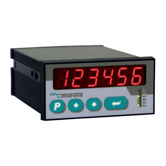
Most compact unit including operator panel for direct access and
RS232 interface for remote access
PROFIBUS DP interface available (option)
CT34002a_e.doc / Nov-15
CT340 and CT641
Operating Instructions
Page 1 / 42
Advertisement
Table of Contents

Subscribe to Our Youtube Channel
Related Manuals for Motrona CT340


Summary of Contents for Motrona CT340
- Page 1 CT340 and CT641 High Performance Low Cost Controller for Rotating Cutters and Printing Rolls Precision controller for Rotating Cutters and Printing Rolls Easy parameter setting and immediately ready to work with minimum commissioning time High accuracy due to high feedback frequency range (300 kHz with TTL encoders and 200 kHz with HTL encoders) ...
- Page 2 Safety Instructions This manual is an essential part of the unit and contains important hints about function, correct handling and commissioning. Non-observance can result in damage to the unit or the machine or even in injury to persons using the equipment! ...
-
Page 3: Table Of Contents
Table of Contents 1. Available Models ......................4 2. Introduction ........................5 3. Electrical Connections ....................6 3.1. Power Supply ........................8 3.2. Auxiliary Outputs for Encoder Supply ................8 3.3. Impulse Inputs for Incremental Encoders ................ 8 3.4. Control Inputs Cont.1 – Cont.4 ..................9 3.5. -
Page 4: Available Models
Where you desire to mount the units on DIN rails inside a cabinet, please refer to the mounting brackets type SM 300 and SM 600 available as accessories. Figure: SM300 mounting bracket for DIN rail mounting of CT340 units CT34002a_e.doc / Nov-15... -
Page 5: Introduction
2. Introduction The CT340 / CT641 units are suitable for control of rotating cutter systems, partial printing screens and rotating punching or sealing applications. The CT340 / CT641 units have been designed for the special requirements of these rotating systems, under consideration of maximum efficiency and accuracy, with minimum stress for all mechanical parts. -
Page 6: Electrical Connections
3. Electrical Connections 1 2 3 4 5 6 7 8 9 10 11 12 13 14 15 16 17 18 19 20 21 23 24 25 26 27 28 29 30 31 32 Com+ (K1 - K4) Example shows wiring K1 out for encoders with Error... - Page 7 Terminal Name Function Common Ground Potential (0V) +5,2V out Aux. output 5.2V/150 mA for encoder supply +24V out Aux. output 24V/120 mA for encoder supply Common Ground Potential (0V) Slave, /B Cutting roll encoder, channel /B (B inverted) Slave, /A Cutting roll encoder, channel /A (A inverted) Master, /B Line encoder, channel /B (B inverted)
-
Page 8: Power Supply
3.1. Power Supply The CT340 synchronizer accepts both, a 17 – 40 volts DC power or a 24 volts AC power for supply via terminals 17 and 1. The current consumption depends on the level of the input voltage and some internal conditions; therefore it can vary in a range from 100 – 200 mA (auxiliary currents taken from the unit for encoder supply not included). -
Page 9: Control Inputs Cont.1 - Cont.4
Remote change of parameters during operation Remote readout of actual values by PLC or PC The figure below explains the connection between the CT340 unit and a PC using the standard Sub-D-9 serial connector For details of the serial communication protocol, please refer to the special “Serpro” manual. -
Page 10: Functional Description
It is a must to use a 4-quadrant drive or a servo drive for the cutting roll, because the CT340 / CT641 must be able to accelerate and decelerate the roll under real closed loop conditions. -
Page 11: System Configuration
It is necessary to adjust the cutting roll drive to its maximum dynamic response (no internal ramps, no integral control loop, high proportional gain), because the CT340 and CT641 will generate the ramps which the drive has to follow with no additional delay Two inputs “Jog / Trim”... -
Page 12: Keypad Operation
5. Keypad Operation An overview of all parameters and explanations can be found under section 7. The menu of the unit uses four keys, hereinafter named as follows: PROG DOWN ENTER Key functions depend on the actual operating state of the unit. Essentially we have to describe three basic states: ... -
Page 13: Direct Fast Access To Cutting Length Setting
Step State Key action Display Comment Normal operation Actual Error Display of the > 2 sec. Parameter group Level: F02 … F06 Select group # F06 Parameter group Confirmation of F06. F06.050 The first parameter of this group is F06.050 Level: F06.051…... -
Page 14: Change Of Parameter Values On The Numeric Level
5.4. Change of Parameter Values on the Numeric Level The numeric range of the parameters is up to 6 digits. Some of the parameters may also include a sign. For fast and easy setting or these values the menu uses an algorithm as shown subsequently. -
Page 15: Code Protection Against Unauthorized Keypad Access
5.5. Code Protection against Unauthorized Keypad Access Parameter group F09 allows to define an own locking code for each of the parameter menus. This permits to limit access to certain parameter groups to specific persons only. When accessing a protected parameter group, the display will first show “CODE” and wait for your entry. -
Page 16: Menu Structure And Description Of Parameters
6. Menu Structure and Description of Parameters All parameters are arranged in a reasonable order of functional groups (F01 to F09) You must only set those parameters which are really relevant for your specific application. Unused parameters can remain as they actually are. 6.1. - Page 17 Command Assignment Keypad protection codes Key Up Function Protect Group F01 Key Down Function Protect Group F02 Key Enter Function Protect Group F03 Input 1 Configuration Protect Group F04 Input 1 Function Protect Group F05 Input 2 Configuration Protect Group F06 Input 2 Function Protect Group F07 Input 3 Configuration...
-
Page 18: Description Of The Parameters
6.2. Description of the Parameters Prior to register setting you must decide which dimensions or length units (LU) you like to use for preset of the cutting length. This could be 0.1mm or 1mm or 0.001 inch or any other resolution you desire. - Page 19 Range Default F02.007 Correction Divider: 0 … 9 Function to provide a digital attenuation of the phase correction signal that is produced, when the drive on mechanical grounds (dead band or backlash) cannot respond. In such a case, it is not desirable to make corrections immediately.
- Page 20 Range Default F02.011 Sampling Time: 0.001 … 9.980 0.001 Sets the internal digital feed forward control with (seconds) respect to dynamics and resolution. Lower set values result in faster response, but less accuracy of the feed forward signal. Higher set values result in better accuracy, but slower response with sudden speed changes.
- Page 21 a. If you have more than one tool but only one single cutting pulse per revolution of the cutting roll, then set register “Cuts per Rev.” to the number of cuts performed by one revolution of the cutting roll. The controller will generate the missing cutting pulses internally. Example: Two cuts per revolution but only one cutting pulse →...
- Page 22 Range Default F02.017 Jog Speed: 0.01 … 10.00 1.00 Speed setpoint in Volt for Jog operations by use of input “Jog forward” or “Jog reverse”. F02.018 Jog / Homing Ramp: 0 … 99 Ramp time in seconds for Jog operations and homing sequence with respect to speed changes between standstill and maximum speed (setpoint 10 V) F02.019...
- Page 23 Range Default F02.024 Cutting Pulse Offset: -999999 … Offset register for virtual displacement of the physical +999999 cutting pulse (generated from encoder index or by proximity). Setting in +/- encoder increments. This register makes superfluous a precise mechanical adjustment of the location of the pulse (the virtual cutting pulse must be located exactly in the peak position of tool penetration).
- Page 24 6.2.4. Definitions for the Slave Encoder Range Default F04.032 Encoder properties 0 … 3 Impulses A, /A, B, /B (2 x 90°) incl. inv. Impulses A, B (2 x 90°) without inv. F04.033 Edge counting 0 … 2 Simple (x1) Double (x2) Full quadrature (x4) F04.034 Counting direction...
- Page 25 6.2.6. Key command assignments Range Default F06.046 Function assignment to key „UP“ 0 … 16 No function Reset Start Immediate Cut Homing n.a. For more details about these n.a. functions see section 7.1 Store to EEPROM Scroll Display n.a. 10= Jog / Trim forward 11= Jog / Trim backward 12= Clear Batch Counter 13= n.a.
- Page 26 6.2.7. Characteristics and functions of the Control Inputs Range Default F06.049 Switching characteristics of input „Cont.1“ 0 … 7 NPN (switch to -), function active LOW NPN (switch to -), function active HIGH NPN (switch to -), rising edge NPN (switch to -), falling edge PNP (switch to +), function active LOW PNP (switch to +), function active HIGH PNP (switch to +), rising edge...
- Page 27 Unconnected NPN inputs are always HIGH (internal pull-up resistor) Unconnected PNP inputs are always LOW (internal pull-down resistor) It is mandatory to assign the Cutting Pulse to one of the inputs 1, 2 or 3 (F06.050 or F06.052 or F06.054 = 6). The selected input is no more available for other purpose.
- Page 28 6.2.9. Special functions Range Default F08.064 Digital input filter: must be set to “0”. 0 … 3 F08.065 Trigger threshold for encoder1 inputs *) 30 … 250 F08.066 Trigger threshold for encoder2 inputs *) 30 … 250 F08.067 Brightness of the 7-segment LED display 0 …...
-
Page 29: Description Of Commands And Outputs
7. Description of Commands and Outputs 7.1. Commands No. Command Description Assignment to Keypad Input Reset Sets the internal differential counter and the analogue correction signal to zero. The cutting roll drive runs solely in analogue synchronization (open loop control) whilst activated Start Start of the automatic cutting procedure. - Page 30 No. Command Description Assignment to Keypad Input Store to Stores actual operational settings to the EEPROM, so EEPROM they remain available also after power down. Scroll Display Selects the source of the digital display. See chapter 7.3 Display for details. Parameter Disables the keypad for any parameter access.
-
Page 31: Outputs
7.2. Outputs Output Terminal Error: X2 / 26 This output goes high when an error is detected during operation (see section 7.4 “Error Messages”). Alert: X2 / 25 Indicates that the cutting roll, with respect to its profile position set point, actually runs with a positive or negative position error higher than the limit set at parameter „Alarm Level“. -
Page 32: Display Of Actual Values
7.3. Display of Actual Values During normal operation it is possible to display an actual value. Two LEDs at the front panel indicate the actual value displayed. You can scroll the actual value on the display by Scroll Display command, which can be assigned either to a key or to an input. Parameter F08.071 “Default Display”... -
Page 33: Error Messages
7.4. Error Messages Upon detection of an error, the cutting roll remains in a closed-loop standstill at home position after termination of the current cut. Output “Error” switches to high and the unit displays a flashing error message “Error…” indicating the error number. To clear an error state either set “Clear Error”... -
Page 34: Steps For Commissioning
8. Steps for Commissioning For easy and uncomplicated commissioning of the CT340 / 641 controllers you need a PC with the actual operator software OS3.x. You can download this software and full instructions, free of charge, from our homepage www.motrona.com. -
Page 35: Running The Adjust Menu
10.000 After entry of all parameters click to “Transmit All” followed by “Store EEPROM” to store all parameters to the CT340 or CT641 controller. At this time, both drives (line and cutting roll) must be adjusted to proper and stable operation over the full speed range. -
Page 36: Set Directions Of Rotation
8.2. Set Directions of Rotation The direction of rotation must be defined for both, master and slave encoder. Make sure the Reset is switched on when you do this (the softkey must show “Reset is ON”) Move the Master encoder into forward direction (manually or by means of a remote speed signal to the Master drive). -
Page 37: Setting Of The Proportional Gain
8.4. Setting of the Proportional Gain The register “Gain Correction” determines how strong the controller responds to position and speed errors of the drive. In principle, this setting therefore should be as high as possible. However, depending on dynamics and inertia of the whole system, too high gain values will produce stability problems. - Page 38 If, despite of this, your cutting results should not satisfy you in terms of accuracy or synchronism, there are definitely mechanical problems or other external reasons outside of the control loop. The following hints refer to improvements you can make when bar graph display and differential counter indicate unusual characteristics: If many segments of the bar graph display are lit at the same time and the differential counter shows very unstable values:...
-
Page 39: Appendix For Model Ct 641
9. Appendix for model CT 641 9.1. Relay Outputs While model CT340 provides high-speed transistor outputs only, model CT641 provides four additional relay outputs, operating in parallel to the high-speed transistor outputs K1 – K4. All electrical connections of CT 641 are fully similar to CT 340, except that with CT 641 models the back plane is equipped with an additional terminal strip X3 providing the relay connector: 9.2. -
Page 40: Specifications And Dimensions
10. Specifications and Dimensions AC power supply 24 V~ +/-10%, 15 VA DC power supply 24V- (17 – 40V), approx. 100 mA (+ encoders) Aux. encoder supply outputs: 2 x 5,2 VDC, 150 mA each 2 x 24V DC, 120 mA each Inputs 2 universal encoder inputs 4 digital control inputs HTL (Ri = 3.3 kΩ) - Page 41 Dimensions of model CT340: 110,0 (4.331’’) 91,0 (3.583) 96,0 (3.780’’) Panel cut out: 91 x 44 mm (3.583 x 1.732’’) CT34002a_e.doc / Nov-15 Page 41 / 42...
- Page 42 Dimensions of model CT641: 110,0 (4.331’’) 96,0 (3.780’’) With optional plexi glass cover for protection class IP65 (motrona part # 64026) 9,0 (.345) 129,0 (5.079) 140,5 (5.531) 18,5 (.728) Panel cut out (b x h): 89 x 91 mm (3.504’’ wide x 3.583’’ high) CT34002a_e.doc / Nov-15...
Need help?
Do you have a question about the CT340 and is the answer not in the manual?
Questions and answers