
Related Manuals for Norfield MAGNUM


Summary of Contents for Norfield MAGNUM
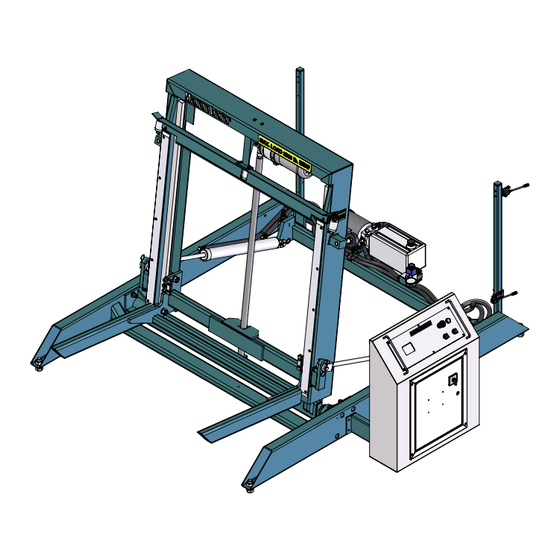
- Page 1 MAGNUM DOOR LOADER PARTS & OPERATORS MANUAL Effective S/N: LM-6927 Document Number: 17-301 Release: 4...
- Page 2 First Release: July, 2007 Second Release: January, 2008 Third Release: October, 2009 Fourth Release: January 2015...
- Page 3 Norfield 422 Otterson Dr. Chico, Ca. 95928 Technical Support: (530) 891-4214 - Parts: (800) 824-6242 Serial No: _____________________ Date Sold: _____________________ Norfield is the name that represents Quality, Reliability, Support, Innovation and True Customer Service. We have been dedicated to providing quality products and excellent Norfield customer service for more than 40 years.
- Page 4 It provides an economical solution for feeding doors on edge eliminating the need to lift, turn and feed each door. Prior to shipment from our factory each Norfield machine is put through a series of tests and inspec- tions to insure that you are provided with the highest quality product for your business.
-
Page 5: Table Of Contents
TABLE OF CONTENTS Safety Lockout Procedures Specifications Parts Replacement Policy / Warranty Contact and Order Information Installation Operation Trouble Shooting Parts Drawings... -
Page 6: Safety
SAFETY SAFETY Safety considerations are an important element of machine installation and operation. Active- ly maintaining a safety mind set about yourself and others while working around or on the equipment is of primary importance. Operators and maintenance personnel should refer to the safety informa- tion on the following pages to familiarize themselves with warning labels and practices providing for safe operation and servicing of this machine. - Page 7 SAFETY Do not operate this machine unless all guards are in place and working cor- rectly. If any guards or hazard labels are missing or damaged call Norfield’s Service Department immediately and request a replacement at (800) 824-6242. Read and understand the operator’s manual before using this machine. Fail- ure to follow proper operating instructions could result in death or serious injury.
- Page 8 Woodworking machinery is inherently dangerous, common sense and good safety practices are your best defense against injury. If you have any questions regarding the correct operation of the machine and safety procedures in this manual call the Norfield Service Department at (800)-824-6242...
-
Page 9: Lockout Procedures
LOCKOUT PROCEDURES The following is an example of the minimum requirements for a lockout/tagout procedure. Norfield strongly recommends that your company establish its own written procdeure. OSHA Regulation 1910.147 establishes a minimal lockout/tagout procedure to assist employers in the development of their own Lockout Procedures All employees will comply with these procedures. - Page 10 LOCKOUT PROCEDURES 3. Operate the switch, valve or other energy isolating devices so that all energy sources (electrical, mechanical, pneumatic, hydraulic, etc.) are disconnected or isolated from the equipment and/or circuits. Stored energy, such as that in capacitors, springs, elevated machine members, rotating flywheels, hydraulic systems, and air/gas, steam or water pressure, etc., must also be dissipated or restrained by methods such as grounding, repositioning, blocking, bleeding down, etc.
-
Page 11: Specifications
SPECIFICATIONS SPECIFICATIONS The Magnum Door Loader was designed as a companion machine to the Magnum Door Machine. It is specifically used to load doors onto the Magnum Specifications Electrical Requirements AC Line Phase Hertz Amperage 3Ø 60Hz 220/240 60Hz 3Ø... -
Page 12: Parts Replacement Policy / Warranty
All parts manufactured by Norfield and found to be defective will be given appropriate credit. All parts not manufactured by Norfield are covered by their respective manufacturer’s warranty and will be sent to the original manufacturer for credit. When, and if, credit is issued to Norfield, we will in turn issue credit to your account. -
Page 13: Contact And Order Information
Norfield is the name that represents Quality, Reliability, Support, innovation and True Custom- er Service. We are dedicated to providing world class customer care. Norfield has been provid- ing quality care in the pre-hanging door industry for over 40 years and has earned a reputation for setting the standard for innovation, reliability, full technical support, machine parts and a full line of industrial woodworking tools and accessories. -
Page 14: Installation
If any shortages are noticed, the freight carrier and Norfield Industries should be notified immediately. While any shortages, other than back orders, or freight damages are the complete responsibility of the freight carrier, Norfield Industries desires to be notified so that the replacement of lost or damaged parts can be expedited. - Page 15 With the use of a forklift move the machine to its permanent position within your shop. This space should have been predetermined and electrical power should be installed prior to the machines arrival. To complete the installation and setup of your new Magnum Door Loader the following list of tools will be necessary.
- Page 16 6 If there is a chance that you will move the machine again, the lifting brackets should be stored in a safe place. In the event that you need to move a Norfield Magnum Door Loader and the lift ing brackets can not be located, they can be ordered from Norfield Industries. The parts necessary are, (2) 6850-130 lift bracket, (2) 6850-039 lift bracket mount, (8) ½”...
- Page 17 1-5 INSTALLING LOADER BASE PLATES During the course of normal operation the door stacks being loaded onto the Norfield Magnum Door Loader may impact the vertical wear strips with suffi- cient force to move the machine and cause misalignment with the door machine.
- Page 18 INSTALLATION 1-6 INSTALL THE CONTROL STAND 1 Install the control stand. Unbolt the control stand from its shipping position. Carefully move the control stand into the operating position and install the four bolts. See fig. 1-5. 2 Before tightening the mounting bolts, adjust the control stand support legs so that the control stand mounts are flat against the frame.
- Page 19 INSTALLATION GROUND ELECTRICAL CONNECTION PANEL POINT CONNECT THREE PHASE POWER TO TERMINALS 1, 3 & 5 CONNECT HIGHEST VOLTAGE LEG TO TERMINAL #3 DISCONNECT SWITCH FIGURE 1-6 1-8 CHECK MOTOR ROTATION 1 When you are confident that all of the electrical connections are correct, close the main electrical cabinet door and tighten the screws.
- Page 20 2 Set the Magnum infeed bed to the height you would normally use for your standard undercut. 3 Loosen the lock nuts and adjust the tilt stop pads so the door rolls out of the Magnum Door Loader and on to the Magnum infeed bed smoothly. See Figure. 2-1.
- Page 21 1 The receiver should be adjusted, using the long slots in the mount plate, so the door stops ¼” – ½” out from the white wear strip of the Magnum. If there is not enough adjustment in the slots, it will be neces sary to move the machine to compensate.
- Page 22 1 Pull the top door off the loader and onto the magnum infeed bed. 10 seconds after the door clears the photo sensor the machine will automatically position the next door to be loaded.
- Page 23 (Electrical/Elec tronic Contact Cleaner), wipe dry. DO NOT LUBRICATE! 6 The oil in the hydraulic pump should be changed every 5 years. Replace with Norfield 10wt turbine oil. 4.2 GENERAL MAINTENANCE COMMENTS 1 A clean machine is essential for superior performance and reduced maintenance.
-
Page 24: Trouble Shooting
TROUBLE SHOOTING SECTION 5 TROUBLE SHOOTING 5.1 INPUT & OUTPUT LIGHTS As the machine sequences the output and input lights on the controller turn on and off. These lights can be an invaluable troubleshooting tool. As an example, if you press the Auto Start Button and the Auto Start Light on the controller does not come on when the button is held down, then the controller is not getting the start input, and the machine will not cycle. - Page 25 TROUBLE SHOOTING 5.2 SYMPTOM SOLUTION MATRIX Symptom Probable Cause Solution Machine does not index correctly Index is already down all the way. There is no input from the Index Full Down Sensor ndex Full Down Sensor cable is discon- (Input light 06 is off). nected.
- Page 26 TROUBLE SHOOTING Symptom Probable Cause Solution Machine does not tilt up Machine is already tilted up all the way. There is no input from the tilt full up Sen- Tilt up sensor cable is disconnected sor (input light05 is off Tilt full up sensor cable is defective There is no input from tilt up switch.
- Page 27 TROUBLE SHOOTING Symptom Probable Cause Solution Machine does not tilt down Machine is already tilted down all the way. There is no input from the Tilt Full Tilt Full Down Sensor cable is disconnected. Down Sensor (Input light 06 is off) Tilt Full Down Sensor or cable is defective.
- Page 28 TROUBLE SHOOTING Symptoms Probable Cause Solution Machine will not perform automatic operations When the Auto Start Button is pushed, nothing happens. (Input light 04 stays Auto Start Switch is defective. off when Auto Start Button is pushed) Machine is not tilted all the way down. Tilt Full Down Sensor is out of adjust- ment.
- Page 29 SERVICE DOCUMENTS SECTION 6 SERVICE DOCUMENTS...
- Page 30 SERVICE DOCUMENTS...
- Page 31 SERVICE DOCUMENTS BOM Table ITEM NO. PART NUMBER DESCRIPTION QTY. * * * * * 1/4-20 x 3/4" SHCS * * * * * 1/4" Flat Washer * * * * * 1/4" Spring Lock Washer * * * * * 1/4-20 Hex Nut * * * * * 10-24 x 5/8"...
- Page 32 SERVICE DOCUMENTS...
- Page 33 SERVICE DOCUMENTS BOM Table ITEM NO. PART NUMBER DESCRIPTION QTY. * * * * * 1/4-20 x 1/2" BHCS * * * * * 1/4-20 x 3/4" FHCS * * * * * 1/4-20 x 1/2" FHCS * * * * * 3/8-16 x 3/4"...
- Page 34 SERVICE DOCUMENTS...
- Page 35 SERVICE DOCUMENTS BOM Table ITEM NO. PART NUMBER DESCRIPTION QTY. * * * * * 1/2" Flat Washer * * * * * 1/2" Spring Lock Washer * * * * * 1/2-13 x 1-1/2" Hex Bolt * * * * * 1/4-20 x 3/4"...
- Page 36 SERVICE DOCUMENTS...
- Page 37 SERVICE DOCUMENTS ITEM PART NUMBER DESCRIPTION QTY. 16-013 PGL-25-3000S Gauge 16-018 High Pressure Nipple 16-019 Long Hyd. Hose 16-019 Long Hyd. Hose 16-020 Short Hyd. Hose 16-020 Short Hyd. Hose 16-021 Pump Hose 16-022 Check Valve, Hydraulic 16-023 High Pressure 45 16-024 Pump Hose x 18"...
- Page 38 SERVICE DOCUMENTS...
- Page 39 SERVICE DOCUMENTS ITEM PART NUMBER DESCRIPTION QTY. * * * * * Din Rail (8", 11-220) 11-1071 Terminal Block 11-1160 Terminal Blk Barrier, AB 1492-PP3 11-1426 Fuse holder, AB 1492-WFB4 11-1448 Fuse,Bussman GMA-250MA 11-1558 Switch, Emerg. Stop, AB 800FP-MT44 11-1560 Contact Block, NC, AB 800F-X01 11-1561 Push Button, Flush, Green...
- Page 40 SERVICE DOCUMENTS ELECTRICAL PANEL 208/230V 6850-701...
- Page 41 SERVICE DOCUMENTS PART ITEM DESCRIPTION QTY. NUMBER * * * * * Din Rail 7", ( 11-220) * * * * * Din Rail 5-1/2" ( 11-220) * * * * * Wire Duct 1 x 2 x 16-15/16" * * * * * Iboco COV-22 Duct Cover x 31"...
- Page 42 SERVICE DOCUMENTS ELECTRICAL PANEL 460v 6850-702...
- Page 43 SERVICE DOCUMENTS ITEM PART NUMBER DESCRIPTION QTY. * * * * * Din Rail 5-1/2" ( 11-220) * * * * * Din Rail 7", ( 11-220) * * * * * Wire Duct 1 x 2 x 16-15/16" * * * * * Iboco COV-22 Duct Cover x 31"...
- Page 44 SERVICE DOCUMENTS...
- Page 45 SERVICE DOCUMENTS MAGNUM DOOR LOADER ELECTRICAL SCHEMATIC (208V/230V) ITEM PART NO. DESCRIPTION QTY./ ASSY 11-938 S&S LA7-63-1753 3 POLE SWITCH 11-752 S & S LFS2-E-6-175I HANDLE ASSEMBLY 11-696 S & S LA2-G2853 EXTENSION MODULE 11-1121 AB 1492-CB3H100 CIRCUIT BREAKER 11-1776...
- Page 46 SERVICE DOCUMENTS...
- Page 47 SERVICE DOCUMENTS...
- Page 48 SERVICE DOCUMENTS...
- Page 49 All parts manufactured by Norfield and found to be defective will be given appropriate credit. All parts not manufactured by Norfield are covered by their respective manufacturer’s warranty and will be sent to the original manufacturer for credit. When, and if, credit is issued to Norfield, we will in turn issue credit to your account.
- Page 50 Norfield is the name that represents Quality, Reliability, Support, innovation and True Custom- er Service. We are dedicated to providing world class customer care. Norfield has been provid- ing quality care in the pre-hanging door industry for over 40 years and has earned a reputation for setting the standard for innovation, reliability, full technical support, machine parts and a full line of industrial woodworking tools and accessories.
- Page 51 This Page is Intentionally Blank...
Need help?
Do you have a question about the MAGNUM and is the answer not in the manual?
Questions and answers