
Subscribe to Our Youtube Channel
Related Manuals for Norfield magnum


Summary of Contents for Norfield magnum
- Page 1 SIGNATURE SERIES MAGNUM OPERATOR’S MANUAL Effective S/N: DJ-2832-95 Release: 1 Document Number: 17-350...
- Page 2 First Release: September, 2008...
- Page 3 Norfield Industries P.O. Box 459 Chico, Ca. 95927 Technical Support: (530) 891-4214 - Parts: (800) 824-6242 Serial No: _____________________ Date Sold: _____________________ Norfield Industries is the name that represents Quality, Reliability, Support, Innovation and True Customer Service. We have been dedicated to providing quality products and Norfield Industries excellent customer service for more than 40 years.
-
Page 4: Table Of Contents
TABLE OF CONTENTS Safety Lockout Procedures Specifications Location of Major Components Section 1 - Installation & Setup Section 2 - Operation Section 3 - Settings & Adjustments Section 4 - Special Adjustments Section 5 - Maintenance Section 6 - Troubleshooting Warranty &... -
Page 5: Safety
SAFETY SAFETY Safety considerations are an important element of machine installation and operation. Actively maintaining a safety mindset about yourself and others while working around or on the equipment is of primary importance. Operators and maintenance personnel should refer to the safety informa- tion on the following pages to familiarize themselves with warning labels and practices providing for safe operation and servicing of this machine. - Page 6 SAFETY Do not operate this machine unless all guards are in place and working cor- rectly. If any guards or hazard labels are missing or damaged call Norfield’s Service Department immediately and request a replacement at (800) 824-6242. Read and understand the operator’s manual before using this machine. Fail- ure to follow proper operating instructions could result in death or serious injury.
- Page 7 Woodworking machinery is inherently dangerous, common sense and good safety practices are your best defense against injury. If you have any questions regarding the correct operation of the machine and safety procedures in this manual call the Norfield Industries Service Depart- ment at (800)-824-6242...
-
Page 8: Lockout Procedures
LOCKOUT PROCEDURES The following is an example of the minimum requirements for a lockout/tagout procedure. Norfield strongly recommends that your company establish its own written procedure. OSHA Regulation 1910.147 establishes a minimal lockout/tagout procedure to assist employers in the development of their own Lockout Procedures All employees will comply with these procedures. - Page 9 LOCKOUT PROCEDURES 3. Operate the switch, valve or other energy isolating devices so that all energy sources (electrical, mechanical, pneumatic, hydraulic, etc.) are disconnected or isolated from the equipment and/or circuits. Stored energy, such as that in capacitors, springs, elevated machine members, rotating flywheels, hydraulic systems, and air/gas, steam or water pressure, etc., must also be dissipated or restrained by methods such as grounding, repositioning, blocking, bleeding down, etc.
-
Page 10: Specifications
8.5 w/ optional air screwdriver from compressor OR 3/4” I.D. minimum when more than 20 feet from compressor. 3 Phase Motor Specifications Application Motor Part Number Volts Amps Lock Drill Norfield 6801-021 208/230 5.9/5.9 Latch Drill Norfield 6802-032 208/230 3.1/2.8 Sander... - Page 11 SPECIFICATIONS Machine Capabilities Door Width 1’-0” - 4’-0” Door Height Up to 9’-0” Door Thickness 1-3/8” - 2-1/4” Jamb Width 2-1/2” to 10-1/2” Jamb Length Up to 9’-0” Jamb Thickness 1/2” - 1-5/8” Stop Thickness 1/2” Maximum Butt Spacing Variable: 6-1/2” Minimum from top of Door Butt Radius 1/4”...
-
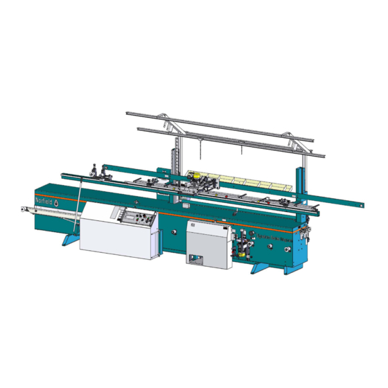
Page 12: Location Of Major Components
LOCATION OF MAJOR COMPONENTS... - Page 13 LOCATION OF MAJOR COMPONENTS...
-
Page 14: Section 1: Installation & Setup
1-1 UNCRATING AND POSITIONING THE MACHINE: The shipping crate for the Magnum is made up of a rigid wood base to which the machine is secured. A protective plastic cover and wood framework surround the machine. Also, a box containing small com- ponents and spare parts is usually enclosed in the crate. - Page 15 INSTALLATION & SETUP ALLOW 3' TO 4' CLEARANCE BETWEEN BACK OF MACHINE AND WALL 12-1/2" 45" MATERIAL FLOW 19'-0" FIGURE 1-1 (TOP VIEW) Position the machine with the dimensions in Fig 1-1 in mind. If the machine is going to be positioned near a wall, it is recommended that 3’...
-
Page 16: Air Supply And Connections
1-4 AIR SUPPLY AND CONNECTIONS: The Magnum requires 2.2 CFM of clean, dry air @ 90 PSI (8.5 CFM if air screwdriver and pre-drill is used) for proper operation. The air supply is connected to the machine at the filter-regulator-lubricator (FRL) unit located on the outfeed end of the main frame (FIG 1-2). - Page 17 (see Figure 1-2). If the Norfield Vacuum unit was purchased with this machine, a cord end is provided on the backside of the machine (230V Phase 3 @ 10A) for automatic starting.
-
Page 18: Section 2: Operation
SECTION 2: OPERATION 2-1 PREFACE: The following is a brief description of the operation procedures of the Magnum. It is recommended that before processing a door, the operator should make sure that the machine is properly adjusted for door width, undercut, hinge size and location, lock height, backset, size of lock and latch bores and size of the faceplate rout. -
Page 19: Operating The Machine
OPERATION 2-2 OPERATING THE MACHINE 1. Turn on SIZER, POWERFEED, and DRILLS motors (In that order). These motors should remain “ON” unless the machine is to be idle for an extended period of time. Please refer to figure 2.2 below. 2. - Page 20 OPERATION 3. Pick up a door and turn it up on edge so that it can be sighted for straightness. If a bow is noticed, place the door on the infeed bed so that the bow is toward the machine (if possible). This way the bow will be away from the stop on the jamb when the door is closed.
- Page 21 OPERATION 11. Mortise the door and jamb. When the mortise is complete the router carriage should be stopped in the forward position over the door. This positions the router carriage so that when it is lifted it is captured in the appropriate position for lowering the next time. If you fail to do this, the next time the router carriage is lowered it will bring the bit down into the jamb.
- Page 22 THIS PAGE IS DELIBERATELY LEFT BLANK...
- Page 23 SETTINGS AND ADJUSTMENTS SETTINGS AND ADJUSTMENTS 3-1 Regulator Setting 3-1 Air Tool Lubricator Setting 3-3 Adjustment for Door Width 3-4 Adjustment for Nominal Width Doors 3-5 Adjustment for Odd Width Doors 3-6 Undercut 3-7 Backset Adjustment 3-8 Lock Height 3-9 Header Clearance 3-10 Changing the Lock Bit 3-11 Changing the Latch Drill Bit 3-12 Changing the Lock Bore Back-Up Block...
-
Page 24: Section 3: Settings & Adjustments
SETTINGS & ADJUSTMENTS SECTION 3: SETTINGS & ADJUSTMENTS: 3-1 REGULATOR SETTING: Set the regulator at 90 psi. The regulator adjustment knob is located on top of the regulator body. To adjust the pressure, lift the knob to unlock it, turn clockwise to increase the regulated pressure or counter-clockwise to reduce the pressure. Push the knob back in to “lock the setting. -
Page 25: Adjustment For Door Width
SETTINGS AND ADJUSTMENTS 3-3 ADJUSTMENT FOR DOOR WIDTH: The top section can be raised or lowered to adjust the machine for any door width between 1-6 and 4-0. There are two methods for establishing door width: 1) index at 2” nominal widths 2) stop the width adjustment at any increment using the width scale. -
Page 26: Undercut
SETTINGS & ADJUSTMENTS 3-6 UNDERCUT: The Magnum is designed to size and bevel doors to an exact width. Since many doors come from the manufacturer at nominal width, most pre-hung door manufacturers size all doors 1/16” to 3/16” under nominal size. An 1/8” undercut is most common. A 2’-0” door undercut 1/8” would be 23-7/8” from the hinge edge to the long point of the bevel. -
Page 27: Backset Adjustment
Lock height is defined as the distance from the center of the lock bore to the top of the door. On the Magnum, lock height is determined by a door stop that references the top of the door to the Lock Drill and Latch Drill. -
Page 28: Header Clearance
4. Position the door so that you can see the line centered in the back-up block lock bore hole, then clamp the door. Norfield recommends that you draw a line on the back up block in the center bottom of the hole to increase accuracy of this step. -
Page 29: Changing The Lock Bit
2-3/4” backset because the bores will overlap. NOTE: Backup blocks must be exactly 3/4” thick or latch drill centering will be changed. Backup blocks can be purchased from Norfield Tools & Supplies @ 1-800-824-6242. 3-13 SANDER ADJUSTMENT: The sander is designed to relieve the sharp corners on the lock edge left by the sizer/ cutterhead. -
Page 30: Changing The Butt Spacing
SETTINGS & ADJUSTMENTS 3-14 CHANGING BUTT SPACING: From time to time you may need to change your butt spacing on an existing index bar, or set up a new index bar. To accomplish this, the following procedure is suggested: 1. If changing an existing index bar, use a metal scribe, mark the location of the index blocks when they are set for your standard spacing so you can accurately and quickly return them to standard. -
Page 31: Changing Mortise Size
SETTINGS AND ADJUSTMENTS 3-15 CHANGING MORTISE SIZE: When all three stop tabs are in the path of the stop bolts (as shown in figure 3-7 below) the mortise will be 3-1/2” wide. As stop tabs are rotated out of the path of the stop bolts the mortise width will increase in 1/2”... -
Page 32: Mortising Flat Jambs
SETTINGS & ADJUSTMENTS 3-17 MORTISING FLAT JAMBS: When mortising flat jambs (jambs with no stop applied) the stop system shown below in figure 3-9 is used to control the movement of the router into the door and into the jamb. The stop dog is rotated to the “down”... -
Page 33: Butt Router For Exterior Jamb And Mullions
5 minutes. GENERAL USE: The extended range router operates in a similar fashion as the standard Magnum butt router with a few variations. The lower indexing pins, 13-597, position the router to perform operations on square edged doors and standard thickness jambs, up to 1-1/2”. -
Page 34: Machining 1'-0" & 1'-4" Doors
SETTINGS AND ADJUSTMENTS 3-20 MACHINING 1’-0” AND 1’-4” DOORS: 1. Adjust the top section to the correct width, either 1-0”, 1-2” or 1-4” on the Index Scale. 2. Pull the 1-0” rollers out all the way. The two 1-0 Rollers are located on either side of the drill assembly above the regular rollers. -
Page 35: Section 4 - Special Adjustments
SPECIAL ADJUSTMENTS SPECIAL ADJUSTMENTS 4-1 Infeed Bed 4-2 Infeed Bed Clutch 4-3 Outfeed Rollers 4-4 Cutterhead Height 4-5 Cutterhead Mandrel 4-6 Cutterhead Replacement 4-7 Cutterhead Motor Drive Belt 4-8 Sanding Wheels Replacement 4-9 Sander Drive Belt 4-10 Replacement of Powerfeed Wheels 4-11 Centering the Latch Drill in the Door 4-12 Aligning the Lock and Latch Drills 4-13 Adjustment of Drill Sensors - Lock Drill... -
Page 36: Infeed Bed
SPECIAL ADJUSTMENTS SECTION 4: SPECIAL ADJUSTMENTS This section describes special adjustments that may become necessary during the life of this machine. This includes those adjustments that will be necessary to make after certain parts are replaced. 4-1 INFEED BED: The infeed bed must be parallel with the outfeed bed. The combination of the four components - infeed bed, cutterhead, outfeed bed, and outfeed rollers add up to a bed-type planner (or Jointer). -
Page 37: Infeed Bed Clutch
SPECIAL ADJUSTMENTS 4-2 INFEED BED CLUTCH: The clutch is located on the infeed bed pivot shaft inside the frame. The purpose of this clutch is to pro- vide the proper amount of friction for the infeed bed handle so that it can be adjusted and will stay where you leave it. -
Page 38: Outfeed Rollers
4-3 OUTFEED ROLLERS: To the right of the outfeed bed, facing the machine, there are four rollers called outfeed rollers. They are positioned at the factory and are referenced to the outfeed bed. It is not likely they will ever get out of adjustment. - Page 39 Moderately tighten 4 bolt that secure mandrel to frame. Tighten bottom set screw. Tighten 4 bolts securely. Replace cutterhead. 10. Place a beveled, straight-edge door on the outfeed bed. Pressing the door firmly against the machine, roll it to your left until the left end of the door is over the cutterhead. Using the pressure of the second powerfeed wheel to hold the door in place, rotate the cutterhead backwards.
-
Page 40: Cutterhead Replacement
SPECIAL ADJUSTMENTS 4-6 CUTTERHEAD REPLACEMENT: The condition of the cutterhead should be inspected daily. The cutterhead knives are carbide which means that anything metallic, either in the door or stuck to it, will chip or actually break one or more knives. -
Page 41: Sander Drive Belt
SPECIAL ADJUSTMENTS Each wheel requires a bushing and a pair of 5/8” flat washers on either side of its hub. Reinstall bushings, wheels, and nuts (NOTE: left-hand treads on the long shaft). Lower the sander with the knob on top of the machine until the wheel is just touching the opening in the frame. -
Page 42: Centering The Latch Drill In The Door
SPECIAL ADJUSTMENTS 4-11 CENTERING THE LATCH DRILL IN THE DOOR: If you process any doors with a 5” backset, then this adjustment, if required, should be made with the backset at 5”. Press door against Main Bar, roll it to door stop and clamp in the usual manner. Bore and drill for the lock and latch bolt. - Page 43 SPECIAL ADJUSTMENTS ALIGNMENT WITH LOCK DRILL FAS- TENERS (4) CENTERING ADJUSTMENT BOLTS FIGURE 4-5 LATCH BORE LOCK BORE FIGURE 4-5A...
-
Page 44: Adjustment Of Drill Sensors - Lock Drill
SPECIAL ADJUSTMENTS 4-13 ADJUSTMENT OF DRILL SENSORS - LOCK DRILL Under normal operating conditions the lock drill will remain properly adjusted for depth of cut. How- ever, should the need arise for adjustment, the sensors on the cylinder will need to be moved. As shown in figure 4.6 below there are three sensors. -
Page 45: Latch Plate Mortise Centering
SPECIAL ADJUSTMENTS LATCH BORE LIMIT SENSOR SHORT STROKE SENSOR HOME SENSOR FIGURE 4-7 4-15 LATCH PLATE MORTISE CENTERING Centering the latch plate mortise in the edge of the door is accomplished by adjusting the nuts securing the template holder posts to the frame. Be sure to retain the 1/16”... -
Page 46: Latch Plate Mortise Depth
SPECIAL ADJUSTMENTS 4-16 LATCH PLATE MORTISE DEPTH: To establish the vertical travel of the latch mortising assembly, lift the latch routing lever by activating the button in the handle (no door in the machine and with the motor switch off). Check to see that the base of the template guide on the control weldment does not touch the bottom surface of the template holder. -
Page 47: Jamb Rack Adjustment
SPECIAL ADJUSTMENTS 4-18 JAMB RACK ADJUSTMENT: Angular Adjustment The jamb supports should be at a 90 degree angle from the face of the door. This can be checked using a framing square. The jamb rack (aluminum extrusion with eight (8) jamb supports) can be rotated to achieve the correct angle. -
Page 48: Leveling The Router Carriage
SPECIAL ADJUSTMENTS Parallel Adjustment The jamb needs to be parallel with the edge of the door for consistent hinge mortising. This can be checked by raising the jamb to the correct height and checking the relationship between the face of the jamb and the edge of the door at both ends of the machine using a framing square set flat on the jamb and the edge of the door. - Page 49 SPECIAL ADJUSTMENTS adjusting bolts equally to attain the 1/32” gap. Retighten the screws. If the jamb reference bars do not rest flat on the door edge, the following procedure will correct this (refer to figure 4-10). 1. Make sure that the door edge is square 2.
-
Page 50: Changing The Butt Router From 0 To 3-1/2 Deg
4-20 CHANGING THE BUTT ROUTER FROM 0 TO 3-1/2 DEG. This feature allows the Magnum to machine the hinge mortises flush with the beveled edge of a double- beveled door. The jamb can be held and machined at the same angle by installing the 6 jamb riser wedges (item # 0001-741) which are included with the standard machine. -
Page 51: Butt Router Carriage Bushings
Plus you save the down time. CONTACT NORFIELD’S SERVICE DEPARTMENT FOR ADVICE IF YOU PLAN ON CHANGING THE ROUTER BUSHINGS YOURSELF. -
Page 52: Section 5 - Maintenance
2. Only use the correct inserts for this cutterhead for proper operation, The replacement blades are available from Norfield Tools and Supplies. 3. The head turns in excess of 7000 RPM and any imbalance will result in severely shortening the life of the bearings in the cutterhead mandrel, in addition to giving a poor finish to the door edge. - Page 53 For this reason if you do not have an in-plant air cleaning system, we suggest you contact the Norfield Service Department or your local air system supplier for assistance in correcting this problem. Water present in air cylinders and valves will severely shorten their life by up to 90%! Check the air filters daily see figure 3.1.
- Page 54 MAINTENANCE 5-9 SANDER BELT: Inspect the sander drive belt weekly for tightness, cracks or hard spots at the splice. When adjusting the tension of the belt it is important not to over tighten the sander double V-belt as this will severely shorten the life of the belt.
-
Page 55: Section 6 - Troubleshooting
TROUBLE SHOOTING 6-1 PREFACE: The first portion of this section is to help familiarize you with the operation of the Magnum by briefly describing what actually happens (mechanically, pneumatically and electrically) when you “push the but- ton”, refer to Figure 6.1 for additional assistance. The second and third portions of this section deals with troubleshooting the machine. -
Page 56: Trouble Shooting
TROUBLE SHOOTING 6-3 CONTROLLER INPUTS AND OUTPUTS Lock drill on/off..................Controller light IN-0 (on when active) Latch Drill on/off..................Controller light IN-1 (on when active) Latch Home Sensor................Controller light IN-2 (on when Latch drill is down) Latch return Sensor................Controller light IN-3 (on when Latch drill is up) Lock Home Sensor ................Controller light IN-4 (on when Lock drill is retracted) Lock Return Sensor ................Controller light IN-5 (on when Lock drill is extended) Clamp Pedal..................Controller light IN-6 (on when Clamp pedal is depressed) - Page 57 TROUBLE SHOOTING 0. Lock Drill On 0. Width Buzzer 1. Latch Drill On 1. Width Up 2. Latch Drill Home 3. Latch Drill Return 2. Width Down 4. Lock Drill Home 5. Lock Drill Return 3. Width Slow 6. Clamp Pedal 4.
- Page 58 TROUBLE SHOOTING As the controller turns functions on and off, output lights on the controller turn on and off, the pneumatic control valves also have a indicator lights that come on when the valve is activated. If the controller is providing an output the corresponding control valve light should be on.
- Page 59 6. UV - INSUFFICIENT VOLTAGE WARNING (THIS ERROR IS SELF CORRECTING OPERATION WILL RETURN WHEN THE CORRECT VOLTAGE IS RESTORED) IF A CODE IS DISPLAYED OTHER THAN THE ABOVE OR IF A CODE APPEARS REPEATEDLY, CALL NORFIELD SERVICE FOR ASSISTANCE.
- Page 60 TROUBLE SHOOTING Problem Possible Causes Solutions Cutterhead drive belt is loose Tighten belt Cutterhead blades are dull Replace with sharp cutterhead Beveled edge shows chatter blades marks Bearings in cutterhead mandrel Replace mandrel or bearings are worn out Cutterhead is undersized Replace blades Cutterhead is too low Raise cutterhead mandrel...
- Page 61 TROUBLE SHOOTING Problem Possible Causes Solutions Door is not clamped Move door to proper stop and clamp door Sawdust build-up or other Depress E-Stop to turn off elec- Drill cycle will not start obstruction under latch drill tricity. Disconnect air. Remove preventing it from returning to sawdust or other obstruction “home”...
- Page 62 TROUBLE SHOOTING Problem Possible Causes Solutions Latch drill sensor not operating Adjust sensor and check for sen- sor input light on controller Latch drill feeds but will not Air pressure too low Air pressure must be maintained return at 90 - 100 PSI Slide shafts dirty Clean slide shafts as described in preventive maintenance...
- Page 63 TROUBLE SHOOTING Problem Possible Causes Solutions Adjustment required See adjustment procedures in Undercut does not match scale Section 4-17 readings One or more index blocks have Reset blocks and mark locations moved with a metal scribe. It is recom- Butt spacing has changed mended you check your butt spacing regularly Router bit undersized...
- Page 64 TROUBLE SHOOTING Problem Possible Causes Solutions Latch Drill only will not start Reset tripped Push reset button Faceplate mortise not centered Alignment cone cylinder out of Adjust cylinder position. See on latch bore adjustment section 4-15 Defective contact block Replace Defective relay coil Replace 3 phase motors will not start...
- Page 65 TROUBLE SHOOTING Pushbutton switch is not making Replace contact block contact Width index motor will not run Motor is burned out Repair or replace motor Defective relay Repair or replace relay Faceplate router switch is not Repair or replace making contact Faceplate router is defective Repair or replace Faceplate router motor will not...
-
Page 66: Warranty & Parts Replacement Policy
All parts manufactured by Norfield and found to be defective will be given appropriate credit. All parts not manufactured by Norfield are covered by their respective manufacturer’s warranty and will be sent to the original manufacturer for credit. When, and if, credit is issued to Norfield, we will in turn issue credit to your account. -
Page 67: Contact Information
Norfield Industries is the name that represents Quality, Reliability, Support, innovation and True Customer Service. We are dedicated to providing world class customer care. Norfield has been providing quality care in the pre-hanging door industry for over 40 years and has earned a reputation for setting the standard for innovation, reliability, full technical support, machine parts and a full line of industrial woodworking tools and accessories.
Need help?
Do you have a question about the magnum and is the answer not in the manual?
Questions and answers
The foot pedal stopped working. When pressed it wont clamp the door or start the bore
The foot pedal on the Norfield Magnum may not be working due to misaligned or binding mechanical parts, especially if the mechanisms are clean. Another possible cause is that a foreign substance has collected fine sawdust and dirt, leading to wear in the bushings. Misalignment of parts can cause assemblies, including the foot pedal, to bind and not function properly.
This answer is automatically generated