Table of Contents
Advertisement
Quick Links
HVLS Fans
This manual applies to fans
manufactured beginning
September 2011 with the serial
numbers 10111500 and higher.
User's Manual
Do not install, operate or service this product unless you
have read and understand the Safety Practices, Warnings,
Installation, Operations,
and Installation and Operating Instructions contained in
Maintenance and Parts
this User's Manual. Failure to do so could result in death
or serious injury.
Part No. 6011315C
Advertisement
Table of Contents

Related Manuals for 4Front Engineered Solutions HVLS


Summary of Contents for 4Front Engineered Solutions HVLS
- Page 1 HVLS Fans This manual applies to fans manufactured beginning September 2011 with the serial numbers 10111500 and higher. User’s Manual Do not install, operate or service this product unless you have read and understand the Safety Practices, Warnings, Installation, Operations,...
-
Page 2: Table Of Contents
Indicates a potentially hazardous situation which, if Notice is used to address practices not related to not avoided, could result in death or serious injury. personal injury. 6011315C — HVLS Fans January 2012 ©2012 4Front Engineered Solutions, Inc. ®... -
Page 3: Safety Practices
Keep your body clear of moving parts at all times. All electrical troubleshooting and repair must be done by a qualified technician and meet all applicable codes. If it is necessary to make troubleshooting checks inside January 2012 6011315C — HVLS Fans ©2012 4Front Engineered Solutions, Inc. ®... -
Page 4: Owner's Responsibilities
Modifications or alterations of industrial fans shall be made only with written permission of the original manufacturer. 6011315C — HVLS Fans January 2012 ©2012 4Front Engineered Solutions, Inc. ®... -
Page 5: Fan Kit
Horse Power (Ft) Weight (Lb) Torque (Ft. Lb) Spacing (Ft) 1-1/2 note: For fan installations in facilities over 3,300' above sea level, consult factory for fan performance factors. January 2012 6011315C — HVLS Fans ©2012 4Front Engineered Solutions, Inc. ®... -
Page 6: Fan Information Tag
Once the information tag is in place, the remote is now linked to this specific fan. Do not use with another fan. Remote control panel Fan information tag 6011315C — HVLS Fans January 2012 ©2012 4Front Engineered Solutions, Inc. ®... -
Page 7: Installation Considerations
HVAC systems, etc. In addition, OSHA requirements state that fan blades must be a minimum of 10' above the floor. Consult a 4Front Engineered Solutions authorized distributor ® for assistance with fan placement and extension selection. January 2012 6011315C — HVLS Fans ©2012 4Front Engineered Solutions, Inc. ®... -
Page 8: Installation
I-beams add shims as required. Fasten using the 1/2" dia x 2-3/4" screws, nylock lock nuts and washers supplied by 4Front oriented as shown. Torque to 40-57 ft-lbs. ® 6011315C — HVLS Fans January 2012 ©2012 4Front Engineered Solutions, Inc. ®... - Page 9 4. Fasten the powerhead to the mount assembly using the 1/2" dia x 1-1/2" screws, nylock lock nuts and washers supplied by 4Front, oriented as shown. Torque to 40-57 ft-lbs. See Fig. 6. January 2012 6011315C — HVLS Fans ©2012 4Front Engineered Solutions, Inc. ®...
- Page 10 4. Using a spirit level, individually tighten the turn buckle on each cable until each cable is tight and the powerhead unit is level. 5. Lock the individual turn buckles using the stop nut on each. 6011315C — HVLS Fans January 2012 ©2012 4Front Engineered Solutions, Inc. ®...
- Page 11 Reference chart on page 7 for min. clearance. Safety 2. Verify guy wire tension by attempting to move powerhead links in any horizontal direction. If movement is detected, re- tension guy wires. January 2012 6011315C — HVLS Fans ©2012 4Front Engineered Solutions, Inc. ®...
- Page 12 VFD enclosure and the remote control panel. note: If longer Category 5e cables runs are required, do not exceed 1,000 feet in length. If more than 1,000 feet is required, consult factory. 6011315C — HVLS Fans January 2012 ©2012 4Front Engineered Solutions, Inc. ®...
- Page 13 3. White and green 4. Blue 5. White and blue 6. Green 7. White and brown 8. Brown 1 2 3 4 5 6 7 8 Computer RJ-45 connector pin-out January 2012 6011315C — HVLS Fans ©2012 4Front Engineered Solutions, Inc. ®...
- Page 14 Instruct shop personnel how to use the industrial fan using the operating procedures on page 16. VeriFy oPeration — networK inStaLLation See instructions in publication 6011665. 6011315C — HVLS Fans January 2012 ©2012 4Front Engineered Solutions, Inc. ®...
-
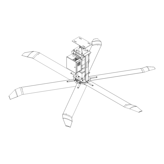
Page 15: Components And Specifications
NEMA standard T.E.F.C., 1-2 HP, continuous duty single or three phase gearboX Double helical gear reduced, sealed lubrication. Fig. 15 Clamp Shim Safety cable Universal mount VFD assembly Guy wires Motor Gearbox Blade Safety links Winglet January 2012 6011315C — HVLS Fans ©2012 4Front Engineered Solutions, Inc. ®... -
Page 16: Electrical System Operation
SwitcH: Three position switch that activates the fan in either the forward or reverse direction or turns the unit off. Fig. 16 Fan speed control Standard installation only Activation switch 6011315C — HVLS Fans January 2012 ©2012 4Front Engineered Solutions, Inc. ®... -
Page 17: Operating Instructions
StoPPing tHe Fan 1. Rotate the three position switch to the OFF position. See Fig. 19. January 2012 6011315C — HVLS Fans ©2012 4Front Engineered Solutions, Inc. ®... -
Page 18: Planned Maintenance
Fig. 20 Legend Symbol Description Cleaning (Location - Frequency) Visually Inspect (Replace Damaged Or Worn) Blow with Compressed Air (Location - Frequency) 6011240 6009762 6011315C — HVLS Fans January 2012 ©2012 4Front Engineered Solutions, Inc. ®... -
Page 19: Troubleshooting Guide
Loosen the the blade bolts. Make sure tick increases with speed. tightened. there is a washer on both ends. Support the blade level (horizontally) before torquing the bolts to 16-18 ft-lbs. January 2012 6011315C — HVLS Fans ©2012 4Front Engineered Solutions, Inc. ®... - Page 20 REMOTE port 2. The display should be reading P-00. If it is not, use the UP or DOWN arrow keys until the display reads P-00. 6011315C — HVLS Fans January 2012 ©2012 4Front Engineered Solutions, Inc.
-
Page 21: Vfd Fault Codes
4-20 F Analog input current out of range Consult technical service SC -Flt Internal drive fault Consult technical service FAULtY Internal drive fault Consult technical service January 2012 6011315C — HVLS Fans ©2012 4Front Engineered Solutions, Inc. ®... -
Page 22: Fire Control System Option
Fire option jumper block See schematic on page 23. If the jumper is left installed, there is no emergency shutdown. 6011315C — HVLS Fans January 2012 ©2012 4Front Engineered Solutions, Inc. ®... - Page 23 Fire controL SySteM oPtion January 2012 6011315C — HVLS Fans ©2012 4Front Engineered Solutions, Inc. ®...
-
Page 24: Electrical Schematics
VFD enclosure and fan. Be certain power is off when wiring to the control box. Failure to do so could result in electrical shock, death or serious injury. 6011315C — HVLS Fans January 2012 ©2012 4Front Engineered Solutions, Inc. - Page 25 VFD enclosure and fan. Be certain power is off when wiring to the control box. Failure to do so could result in electrical shock, death or serious injury. January 2012 6011315C — HVLS Fans ©2012 4Front Engineered Solutions, Inc. ®...
- Page 26 ScHeMaticS, continued VariabLe FreQUency driVe i/o 6011315C — HVLS Fans January 2012 ©2012 4Front Engineered Solutions, Inc. ®...
- Page 27 ScHeMaticS, continued reMote anaLog January 2012 6011315C — HVLS Fans ©2012 4Front Engineered Solutions, Inc. ®...
-
Page 28: Parts List
4Front Engineered Solutions could result in product ® malfunction, breakdown, premature wear, death or serious injury. Optional Hybrid hub assembly 6011315C — HVLS Fans January 2012 ©2012 4Front Engineered Solutions, Inc. ®... - Page 29 BOLT, 1/4-20UNC X 3/4", GR 8 10-10280 BOLT, 7/16-20UNC X 2, GR 5 10-10266 STRUT 60-40001 SAFETY DISC 40-40067-03 BLADE MOUNT HARDWARE KIT 6013298 SAFETY PLATE SPACER 40-40050-01 January 2012 6011315C — HVLS Fans ©2012 4Front Engineered Solutions, Inc. ®...
- Page 30 6010862 - 230V/3 Ph/2 HP (Standard) 6011191 - 230V/3 Ph/2 HP (Network) VFD, 230V/3 PH/2 HP 6010704 LINE REACTOR, 600V, 7.6A, 3% 6010720 CAT 5E COUPLER ASSY 6010711 CONNECTOR ASSY, FIRE CONTROL 6011391 6011315C — HVLS Fans January 2012 ©2012 4Front Engineered Solutions, Inc. ®...
- Page 31 6011391 6011166 - 120V/1 Ph/1 HP (Standard) 6011198 - 120V/1 Ph/1 HP (Network) VFD, 120V/1 PH/1 HP 6011167 CAT 5E COUPLER ASSY 6010711 CONNECTOR ASSY, FIRE CONTROL 6011391 January 2012 6011315C — HVLS Fans ©2012 4Front Engineered Solutions, Inc. ®...
- Page 32 PartS LiSt — reMote controL PaneL Fig. 25 6011315C — HVLS Fans January 2012 ©2012 4Front Engineered Solutions, Inc. ®...
- Page 33 FAN 120V50/60/1PH 1HP 12.5A N 8, 10, 12, 14, 16, 18, 20, 24 6011198 reMote aSSeMbLieS description Fan Sizes Part number REMOTE, FAN ANALOG KELLEY 6011060 REMOTE, FAN ANALOG SERCO 6011061 January 2012 6011315C — HVLS Fans ©2012 4Front Engineered Solutions, Inc. ®...
- Page 34 6011315C — HVLS Fans January 2012 ©2012 4Front Engineered Solutions, Inc. ®...
-
Page 35: Warranty Information
HVLS FAN). 4FRONT’s sole obligation with regard to a HVLS FAN that is claimed to be deficient in material or workmanship shall be as set forth in this Limited Warranty. -
Page 36: Distributor Information
Please direct questions about your fan to your local distributor. Corporate Head Office: Your local distributor is: 1612 Hutton Dr. Suite 140 Carrollton, TX. 75006 Tel. (972) 466-0707 Fax (972) 323-2661 ©2012 4Front Engineered Solutions, Inc. Part No. 6011315C ®...
Need help?
Do you have a question about the HVLS and is the answer not in the manual?
Questions and answers