
Related Manuals for Hawk ORCA

Summary of Contents for Hawk ORCA
- Page 1 Sultan Sonar Manual Rev 1.0 A Higher Level of Performance User Manual ORCA Sonar System Sludge and Settling Level Interface Monitoring For more information, please visit > www.hawkmeasure.com...
-
Page 2: Table Of Contents
Some menu options are missing Wiring Error Codes Wiring - Remote Transmitter Unit Specs & Health Checks Wiring Extension ORCA Electric Actuator Troubleshooting Actuator Cable Specification Part Numbering Remote Electronics Profibus PA - Foundation Fieldbus (PA/FF) Remote Sonar Transducer DeviceNet... -
Page 3: Overview
Sonar System Principle of Operation The ORCA Sonar Series transducer emits a high powered low frequency sonar pulse, which is reflected from the interface density selected. The reflected signal is processed using specially developed software algorithms that eliminate unwanted densities and stratified layers, allowing measurement of Bed or RAS levels. -
Page 4: System Components
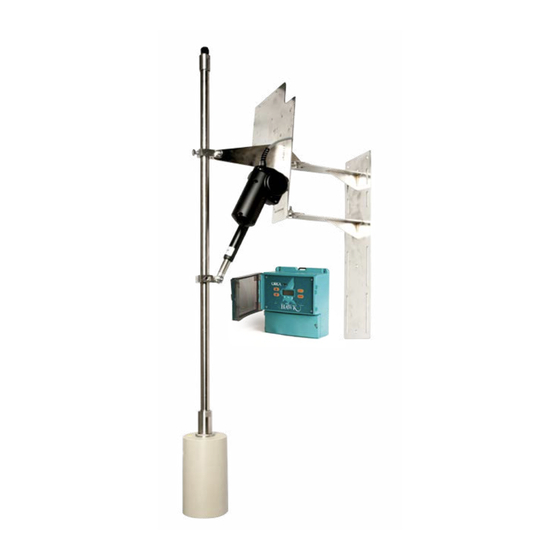
System Components ORCA Sonar System Auto Scum Cleaner OSIR Amplifier OSIRSCA Pictured with Mounting Pole OSIRT Transducer... -
Page 5: Dimensions
Dimensions ORCA Sonar System OSIR Remote Amplifier 111.5 mm (4.4”) 78 mm (3.1”) 192.5 mm (7.6”) 192.5 mm (7.6”) 14 mm (0.6”) 147 mm (5.8”) 174 mm (6.9”) 33.0 29.0 29.0 33.0 182.5 mm (7.2”) 147 mm (5.8”) 50 mm (2”) 158 mm (6.2”) -
Page 6: Osirsce Impact Plate
Dimensions ORCA Sonar System OSIRSCE Impact Plate OSIRSCA Actuator OSIRSCD Floating Sonar 500mm (19.6”) 252mm (9.9”) 500mm (19.6”) 252mm (9.9”) 605mm (23.8”) 252mm (9.9”) 42.5 42.5 α° X = Decent Range Distance from safety rail or Bridge may vary OSIRT302S4 Transducer OSIRT302SH Transducer 1"... -
Page 7: Mounting Bracket
Dimensions ORCA Sonar System Mounting Bracket 240.0 252.0 (A) Base Plate (A) Base Plate 150.0 111.5 Rail / Bridge Mounting U bolts 330.0... -
Page 8: Assembly
Assembly ORCA Sonar System Mounting Bracket / Pole assembly OSIRSCA pictured... -
Page 9: Mounting Bracket / Pole Assembly
Assembly ORCA Sonar System Mounting Bracket / Pole assembly Item Part Number Description OSIRxxx ORCA Transmitter SUNHOOD Stainless Steel Sunhood SA-SS-AAFB Stainless Steel Front Bracket SA-SS-AARB Stainless Steel Rear Bracket LAUS061196E Actuator Actuator (only with OSIRSCA/OSIRSCD) ST-SS-EPEC Pole to Cable Gland Adaptor with M16 cable gland ST-APC-26.8-INT... -
Page 10: Dimensions & Mounting Connection
Dimensions & Mounting Connection ORCA Sonar System Impact Plate Mounting Connection The top of the Impact Plate has 3 x 7mm bolt holes Impact Plate Connection Point which can be secured to an angle iron or equivalent M25 x 1.5 INT bracket. -
Page 11: Mounting & Hardware Assembly
Mounting & Hardware Assembly ORCA Sonar System Impact Plate Assembly Description QTY. Impact Plate Dual Direction Sonar Pole Adaptor Impact Plate Counter Balance Sonar Male Clevis Assembly Sonar Female Clevis Assembly M6×45 Stainless Steel Bolt M10×40 Stainless Steel Bolt M10×12 Stainless Steel Set Screw M10×20 Stainless Steel Set Screw... -
Page 12: Installation Guide
Installation Guide ORCA Sonar System Installation Guide ORCA Transmitter – Mounting Requirements Sonar Transducer – Mounting Requirements Select a suitable mounting position, preferably not in The transducer should be half submerged in the liquid direct sunlight. If necessary utilize a sunshade. -
Page 13: Wiring
RELAY 1 RELAY 2 RELAY 3 ACTUATOR Wiring - Remote Transmitter Wiring Extension RELAY 1 RELAY 2 RELAY 3 ACTUATOR Driving 4-20mA from ORCA to user PLC ANALOG1 TRANSDUCER COMMS DC-IN AC-IN ANALOG2 SONAR 234 REMOTE TRANSMITTER TRANSDUCER ACTUATOR FIELDBUS TRANSDUCER... -
Page 14: Actuator Cable Specification
Actuator Cable Specification ORCA Sonar System Actuator Cable Specification Note 1: Calculations based on: 4.0 Amps max actuator current and; 4.0 Volts drop across max cable length ( 2 wires) Note 1: Note 2: Maximum terminal capacity is 1.5mm, which limits 16AWG cable to35m. -
Page 15: Profibus Pa - Foundation Fieldbus (Pa/Ff)
Profibus PA - Foundation Fieldbus (PA/FF) ORCA Sonar System Profibus PA - Foundation Fieldbus (PA/FF) See dedicated manual for Profibus PA and FF available from http://www.hawkmeausure.com... -
Page 16: Devicenet
Bit 1 Bit 0 Bit0 = Echo was received inside the span. Bit1 = Echo is Confirmed. +Only used for ORCA Sonar Clarity output. Bit3 = Searching is searching for an Echo. BitF = Unit has Failed to detect an Echo. -
Page 17: Profibus Dp
Bit 1 Bit 0 Bit0 = Echo was received inside the span. Bit1 = Echo is Confirmed. Bit3 = Searching is searching for an Echo. BitF = Unit has Failed to detect an Echo. +Only used for ORCA Sonar Clarity output. -
Page 18: Setup Procedure
Setup Procedure ORCA Sonar System Powering The Unit When power is applied the unit will start up automatically. It will scroll through its boot diagnostics and display the serial numbers, software version and model types for the amplifier and transducer The unit will display its default operating screen depending on the App Type selected (default: Bed) on the top line and a distance or % on the bottom line. -
Page 19: Quickset
Setup Procedure ORCA Sonar System Quickset The Quickset menu contains the basic parameters required to get the unit up and running. It is one of the three main menu options in the internal software. Parameter Description Options Unit Adjust displayed measurement unit... -
Page 20: App Type
Setup Procedure ORCA Sonar System App Type App Type is the first output and should be considered the primary measurement. If monitoring Bed level this should be selected here. App Type has three pre-set application types. • Bed (dense/heavy blanket layer). -
Page 21: App Type2
Setup Procedure ORCA Sonar System App Type2 App Type is the second output and should be considered the secondary measurement. This output is sampled and updated at programmed intervals • Bed (dense/heavy blanket layer). • RAS (return activated sludge) • Floc (Flocculent/hindered settling layer). -
Page 22: Output Adjustment
Setup Procedure ORCA Sonar System Output Adjustment The Output Adj menu contains parameters related to adjusting analogue, switch & communication protocol relayed settings. Parameter Description Options FillDamp Adjust first output response time / Value in pulses, approximately 2 pulse per second... -
Page 23: Comms Type
Stop Bits: 1 HAWK Sultan series units act as ‘slave’ devices on a Modbus network. Units are shipped from the factory with a default Modbus address of 1. The Modbus address of any unit can be changed individually if units are to be connected in a multi-drop network. -
Page 24: Cleaning Menu
Cleaning Menu ORCA Sonar System Cleaning Sub-Menu Description Options 6 minutes Keeps the actuator swing extended for the selected time interval before Intvl 3 minutes retracting to normal position 1 minutes 90 seconds Uses Relay 3 to activate an external system (such as a spray cleaner) for the... -
Page 25: Setup Procedure
Velocity Adjusts the internal speed of sound calculation. Adjustable Gain4 default settings Gain-Over-Distance bias The ORCA system uses automatic Gain control Interface Selected (g/l) Default Value to enhance signal tracking during difficult process conditions. Increasing SlopeInc% from 1.5% to 2%- 0.1 - 0.6... -
Page 26: Relay Actions
Relay Actions ORCA Sonar System Relay Actions Set Relay Parameters in Output Adjustment menu Sub-Menu Description Options The two relay levels are RlyL1 and RlyL2 The display will show RlyL1 1, the last 1 indicated the Adjust Relay switch point... -
Page 27: Operating Diagnostics
Operating Diagnostics ORCA Sonar System Operating State In this operational state you can use the buttons to navigate through and view unit diagnostics and other measurements. Space Diagnostic Typical Reading Description 2.622m Bed indicates Bed height measured from Low Level... -
Page 28: Application Calibration
Application Calibration 1/3 Radius ORCA Sonar System How to set up the unit - Bed Level + Hindered / settling layer measurement Parameters for standard setups are located in the 'Quickset' menu. Blanking / non-measured You will need to program the following parameters: zone - App Type - High &... -
Page 29: How To Set Up The Unit - Bed Level + Clarity
Application Calibration 1/3 Radius ORCA Sonar System How to set up the unit - Bed Level + Clarity Parameters for standard setups are located in the 'Quickset' menu. Blanking / non-measured You will need to program the following parameters: zone - App Type - High &... -
Page 30: How To Set Up The Unit - Hindered Layer + Clarity
Application Calibration 1/3 Radius ORCA Sonar System How to set up the unit - Hindered Layer + Clarity Parameters for standard setups are located in the 'Quickset' menu. Blanking / non-measured You will need to program the following parameters: zone - App Type - High &... -
Page 31: Troubleshooting
Programming 'Bed Depth' sets Gain4 to a recommended value based on the • HAWK is constantly updating and improving the expected depth of the Bed level design and accessibility of its products and as a •... -
Page 32: Error Codes
• Contact your local support. the transducer to ensure wires are correct ActuatorErr • If using a junction box ensure you follow HAWK specification for extending cable Before the Actuator sweeps the ORCA will check the incoming voltage to confirm it is not less than •... -
Page 33: Unit Specs & Health Checks
The Transducer power (red wire) should draw Note: Lines 1 & 2 add to total of 10kohm 8-10VDC. If this figure is too high or too low check ORCA power & supplied power as above. Peak extension (default parameters) Disconnect transducer from amplifier. -
Page 34: Orca Electric Actuator Troubleshooting
Troubleshooting ORCA Sonar System ORCA Electric Actuator Troubleshooting The ORCA Sonar system is often used with an in to its home position. Return to the 'Cleaning' electric actuator, powered and controlled by internal parameter and finally select ‘Actuator’ for the electronics in the ORCA Transmitter. -
Page 35: Part Numbering
Part Numbering ORCA Sonar System Remote Electronics Remote Electronics Model OSIR Sonar Level Transmitter, 3 relay alarms Power Supply 24-30VDC (min 5A) 90-250VAC and 24-30VDC (min 5A) Additional Communications (PC comms GosHawk standard) 1 x 4-20mA analog output module with Modbus... -
Page 36: Remote Sonar Transducer
Part Numbering ORCA Sonar System Remote Sonar Transducer OSIRT ORCA Sonar Transducer Transducer Strength Industrial / Mining Transducer 02 (150kHz) Facing & Housing material* S4 Fiberglass face with Polypropylene housing (max 50°C 122°F) SH Full fiberglass high temperature version (max 80°C 180°F) -
Page 37: Automatic Scum Cleaner
Part Numbering ORCA Sonar System Automatic Scum Cleaner OSIRSC Automatic Scum Cleaner Type A 24VDC Electric Actuator incl. Mounting Accessories B Pneumatic Actuator (please consult the factory) D Floating Sonar with 24VDC Electric Actuator incl. Mounting Accessories E Impact Plate Dual Direction plus Mounting Bracket... -
Page 38: Specifications
Specifications ORCA Sonar System Sonar Frequency Selection Operating Temperature • 150kHz • Remote Electronics: -40°C to 70°C • Sonar Transducer Polypropylene: -40°C to 50°C Operating Voltage • Sonar Transducer FRP Fibreglass: -40°C to 80°C. • 90 - 260Vac 50 / 60Hz •... -
Page 39: Warranty And Liability
HAWK specializes in ultrasonic, sonic and sonar level transmitters and have thousands of installed instruments in critical applications around the world. HAWK guarantees the ‘ORCA’ sonar range, when delivered, is free of material defects and undertakes to replace, repair any defective part, free of charge. HAWK will provide two levels of warranty period. - Page 40 GosHawk diagnostic & calibration software; to dial in, calibrate, test, and check the performance of HAWK We Can Help products. This innovative system allows our Global Support Team to assist with commissioning and HAWK understands the difficulties customers face after sales service of HAWK equipment worldwide.
Need help?
Do you have a question about the ORCA and is the answer not in the manual?
Questions and answers