Table of Contents
Advertisement
Advertisement
Table of Contents

Related Manuals for Walvoil SD5

Summary of Contents for Walvoil SD5
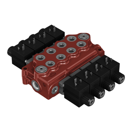
- Page 1 TESTO ITC KORINNA 28mm Allargato MONOBLOCK DIRECTIONAL CONTROL VALVE...
- Page 2 WARNING! All specifications of this catalog refer to the standard product at this date. Walvoil, oriented to a continuous improvement, reserves the right to discontinue, modify or revise the specifications, without notice. WALVOIL IS NOT RESPONSIBLE FOR ANY DAMAGE CAUSED BY AN edition November 2002: INCORRECT USE OF THE PRODUCT.
-
Page 3: Table Of Contents
SD5/1--D ..... . . monoblock valve SD5--S with series circuit .. -
Page 4: Working Conditions
Working conditions This catalog shows technical specifications and diagrams measured with mineral oil of 46 mm /s -- 46 cSt viscosity at 40°C -- 104°F temperature. Nominal flow rating 45 l/min 12 US gpm Operating pressure (maximum) parallel pr tandem circuit 315 bar 4600 psi series circuit... -
Page 5: Dimensional Data
15° 15° 24° 24,5 0.96 1.18 0.91 1.46 1.06 spool in 3.54 Valve type WALVOIL SD5/2- -P Production batch: P0200001 P02 = production year (2002) 102219002 00001 = progressive number MADE IN ITALY Valve code Weight Weight TYPE TYPE TYPE... -
Page 6: Hydraulic Circuit
Plug for open center Allen wrench 8 24 Nm / 17.7 lbft Main relief valve Lever pivot box Standard configuration Configuration with upper inlet and outlet A1 B1 A2 B2 A1 B1 A2 B2 1750 1750 Ex.: SD5/2--P(JG3--120)/18L/18L/AET Ex.: SD5/2--P(JG3--120)/18L/18L/AET--PSA DAT003A... -
Page 7: Performance Data
Performance data (pressure drop vs. flow) Open center From side inlet to side outlet. 15 (US gpm) (bar) (psi) A1 A2 A3 A4 A5 A6 7 sections 4 sections B1 B2 B3 B4 B5 B6 B7 2 sections Flow (l/min) Inlet to work port From side inlet to A port (spool in position 1) or B port (spool in position 2). -
Page 8: Ordering Codes
Valve setting (bar) Valve setting (bar) section following section SD5 / 2 - - P (JG3- - 120) / 1 8 L / 1 8IM . P3(G3- - 100) / AET - - SAE * Body kits Spool options page 11... -
Page 9: A" Side Spool Positioners
Codici di ordinazione “A” side spool positioners page 18 “B” side options page 30 TYPE CODE DESCRIPTION TYPE CODE DESCRIPTION 5LEV105000 Standard lever box 5V08105000 With spring return in neutral position LM10 5LEV205000 Lever box for M10 handlever 5V08105200 With spring return in neutral position and 5LEV105102 Lever box with adjustable flow limiter pin with M6 female thread for dual control... - Page 10 Inlet relief options Direct pressure relief vave VMD5 ( J G 3 - - 120 ) Standard setting in bar (for value see page 8) (2, 3, 4). Adjustable spring type (G, H) Adjustment type Adjustment type : with screw : valve set and locked Wrench 19 Cap code: 3COP117260...
- Page 11 Spool options Type 1 For special requirement, spool 1CS code 3CU1210200 suggested for flow from 15 to 30 l/min -- 4 to 7.9 US gpm and spool 1CEX code 3CU1210230 suggested for flow up to 15 l/min -- 4 US gpm, are available. + 5.5 mm stroke "...
- Page 12 Spool options Type 1A P--B closed, A®T, flow through line (LC) open Type 1B P--A closed, B®T, flow through line (LC) open Type 2 P closed, A--B®T, flow through line (LC) open Type 2H P closed, A--B partially open to tank, flow through line (LC) open DAT003A...
- Page 13 Spool options Type 3 + 5.5 mm stroke " + 0.22 in P ® A Port B plugged Allen wrench 6 - - 24 Nm / 17.7 lbft P--A--T closed, flow through line (LC) open - - 5.5 mm stroke - - 0.22 in A ®...
- Page 14 Spool options Type 5DY It needs special body with extra machining: for information please contact Customer Service. This spool must be coupled with posi- tioner type 13NZ. Also available spool with check valve on A port; type 5WY code 3CU1242320. "...
- Page 15 Spool options Type 5PY It needs special body with extra machining: for information please contact Customer Service. This spool must be coupled with posi- tioner type 13QN. " " + 9 mm stroke Locking force: + 0.35 in 370 N / 83.2 lbf ±10% A--B ®...
- Page 16 Spool options Type 8 It needs special body with extra machining: for information please contact Customer Service. This spool must be coupled with posi- tioner type 13FZ. " + 4.5 mm stroke + 0.18 in P® A , B ® T Allen wrench 5 Allen wrench 4 9.8 Nm / 7.2 lbft...
- Page 17 Spool options Type 8F It needs special body with extra machining: for information please contact Customer Service. + 5.5 mm stroke " + 0.22 in P ® A--B (regenerative) P--A--B--T closed, flow through line (LC) open - - 5.5 mm stroke - - 0.22 in P®...
- Page 18 ”A” side spool positioners With spring return in neutral position 8 kit It’s supplied with standard spring type D (see force--stroke diagram) and available with lighter spring type C (8MC code: 5V08205000) or heavier type E (8ME code: 5V08405000). Force- -stroke diagram 0.2 (in) - - 0.2 - - 0.1...
- Page 19 “A” side spool positioners With spring return in neutral position 8F2 kit Allen wrench 5 Allen wrench 4 9.8 Nm / 7.2 lbft 6.6 Nm / 4.9 lbft Wrench 13 24 Nm / 17.7 lbft Allen wrench 4 36.5 1.44 51.5 2.03 19 kit...
- Page 20 ”A” side spool positioners With detent 9 kit 10 kit Allen wrench 4 Allen wrench 4 6.6 Nm / 4.9 lbft 6.6 Nm / 4.9 lbft Allen wrench 5 Allen wrench 5 9.8 Nm / 7.2 lbft 9.8 Nm / 7.2 lbft 45,5 45.5 1.61...
- Page 21 “A” side spool positioners With detent and sprimg return to neutral position from either directions 9B kit Force- -stroke diagram 0.2 (in) - - 0.2 - - 0.1 (lbf) From position 0 to 1 Allen wrench 4 6.6 Nm / 4.9 lbft From position 2 to 0 From position 1 to 0 - - 20...
- Page 22 6.6 Nm / 4.9 lbft A1 B1 A2 B2 1750 Es.: SD5/2--P(JG3--120)/18MS3L/18MS3L/AET -- KM 2 S 51 51 = with bracket for M51 (IP51) microswitch fixing Assembling kit 67 = with bracket for M67 (IP67) microswitch fixing S = bracket placed on left Nr.
- Page 23 “A” side spool positioners 8MS3 kit: with centralized control for microswitch Other configurations 8MS1 kit microswitch operation in Allen wrench 2.5 position 1 6.6 Nm / 4.9 lbft Allen wrench 4 6.6 Nm / 4.9 lbft 8MS2 kit microswitch operation in position 2 58.3 2.29...
- Page 24 “A” side spool positioners With microswitch and spring return in neutral position 8MG3 kit 8MG3 kit microswitch operation in Microswitch kit with positions 1 and 2 PACKARD male connector 4.06 Wrench 22 42 Nm / 31 lbft Wrench 10 9.8 Nm / 7.2 lbft Allen wrench 4 Other configuration 6.6 Nm / 4.9 lbft...
- Page 25 “A” side spool positioners With microswitch and spring return in neutral position 8M3 kit Allen wrench 4 6.6 Nm / 4.9 lbft notch 1.5 mm / 0.06 in 9.8 Nm / 7.2 lbft Allen wrench 2.5 6.6 Nm / 4.9 lbft 36.5 1.44 2.91...
- Page 26 “A” side spool positioners 8MHE3 kit: with spring return in neutral position and spool positioning ON/OFF signal This module supplies two different ON/OFF signals, related to the direction of the spool. It has two separate contacts which can be normallyopen or normally closed. Connection DIN43650/C (needs connector type C11, see page 62) Connector wiring...
- Page 27 “A” side spool positioners 8P: ON/OFF pneumatic kit Wrench 11 NPT 1/8” - - nr.2 thread 9.8 Nm / 7.2 lbft Allen wrench 4 51,5 6.6 Nm / 4.9 lbft Operating features Pilot pressure ....: min.
- Page 28 5KE2S00270 Kit for 2 sections KE3S0 5KE3S00270 Kit for 3 sections KE4S0 5KE4S00270 Kit for 4 sections KE5S0 5KE5S00270 Kit for 5 sections KE6S0 5KE6S00270 Kit for 6 sections Ex: SD5/2--P(JG3--120)/18ED3L/18ED3L/AET--SAE- -KE2S0- -24VDC KE7S0 5KE7S00270 kit for 7 sections DAT003A...
- Page 29 42 Nm / 31 lbft Inlet line 1750 VRC back pressure Wrench 24 valve (not included) 24 Nm / 17.7 lbft 1.38 Ordering codes (UN- -UNF thread) Ex: SD5/2--P(JG3--120)/18ED3L/18ED3L/VRC- -SAE- - KE2R3- -24VDC TYPE CODE DESCRIPTION KE1R3 5KE1R30270 Kit for 1 section KE2R3...
-
Page 30: B" Side Options
”B” side options Lever controls L type Alluminium with protection boot lever pivot box; it can be rotated 180° (execution L180). (**) Vertical handlever Horizontal handlever assembly assembly Execution L180 0.79 Allen wrench 4 6.6 Nm / 4.9 lbft 1.73 NOTE (*) - - With spool type 5DY (see page 14) (**) -- With spool type 5PY (see page 15) LM10 type... - Page 31 “B” side options Special lever controls Safety levers with lock in neutral complete with handlever; lift handlever knob to operate. LEB type Locking bush Wrench 13 24 Nm / 17.7 lbft Allen wrench 4 0.79 6.6 Nm / 4.9 lbft 1.73 LUP type Available as LUP(R150) configuration, with lenght L = 150 mm / 5.91 in and red knob:...
- Page 32 Wrench 24 - - 24 Nm / 17.7 lbft Flexible cable 3.19 NOTE - - For more information about remote cable control, require appropriate documentation. TQ kit SCF030 remote control CD flexible cables SD5/2 directional control valve without lever boxes DAT003A...
- Page 33 Kit comandi lato “B” LCB mechanical joystick for two sections control Execution LCB4 Pivot section spool Wrench 13 section spool 24 Nm / 17.7 lbft Wrench 10 Allen wrench 5 9.8 Nm / 7.2 lbft Allen wrench 4 - - 6.6 Nm / 4.9 lbft Allen wrench 4 - - 6.6 Nm / 4.9 lbft Wrench 13 - - 24 Nm / 17.7 lbft Wrench 13 - - 24 Nm / 17.7 lbft...
- Page 34 Complete controls 8IM: proportional hydraulic control code 5IDR205071 It can be used with standard spools and body (body kit without seals on spool). Coupling suggested with type 1CS spool (see page 11). 1.10 SAE6 1.50 Allen wrench 5 9.8 Nm / 7.2 lbft Allen wrench 4 Spool 6.6 Nm / 4.9 lbft...
- Page 35 Complete controls 8IM: proportional hydraulic control code 5IDR205021 Connection example Hydraulic pilot control valve series SV01 with curve type 026 Curve 026 (in) (psi) (bar) Stroke (mm) A1 B1 A2 B2 1750 SD5/2--P(JG3--125)/1CS8IM/1CS8IM/AET--SAE+ SV01--S/01W--026Ax4 DAT003A...
- Page 36 It’s necessary special spool and standard body (body kit without spool seals). Due to the large dimension, it’s not possible to assembly more than one control consecutively, except SD5/2- -P and SD5/3- -P that have special bodies with bigger centre--to--centre.
- Page 37 Complete controls 8ESN solenoid control 8ESNLES kit Electric wiring example with safety lever pivot box 8ESNCAE kit with encadp Connector P Þ B P Þ A A Þ T B Þ T To battery Operating features Internal leakage A(B)®T (Dp = 100 bar - - 1450 psi T = 40°C - - 104°F) .
- Page 38 Solenoid direct control with spring return to neutral position. It needs special spools and standard body (body kit without seals on spool). Description example: SD5 / 1 - - P (JG3- - 120) / 1 8ES3 / AET - - SAE - - 24VDC 8ES3 8ES2...
-
Page 39: Complete Control Kits
Complete control 8ES solenoid control 8ES3 kit Electric wiring example double acting 8ES1 kit single acting on A Connector 1 Connector 2 8ES2 kit P Þ A P Þ B B Þ T A Þ T single acting on B To battery Operating condition diagram Operating features... -
Page 40: Outlet Port Options
0.93 0.16 A1 B1 A2 B2 A1 B1 A2 B2 1750 1750 Ex: SD5/2--P(KG3--120)/18L/18L/AE- -SAE Ex: SD5/2--P(KG3--120)/18L/18L/AEK L: hydraulic pilot unloader valve For safety reasons it’s provided with pilot port plugged. Pressure drop curve A2 B2 (US gpm) 1.22 (psi) - Page 41 42 Nm / 31 lbft Push and twist push- -button Wrench 24 for manual override 42 Nm / 31 lbft ISO4400 connection Ex.: SD5/2--P(JG3--120)/18L/18L/AET--EL- -12VDC Wrench 30 (needs C02 connector, see 42 Nm / 31 lbft page 62) Operating features...
- Page 42 Service valves1. All service valves need special body: contact Customer Service. VSC(JG...) VD11 Kit VS VSCT Kit VD1 VD12 VM(...) Kit VM VD13 VM(...) DAT003A...
-
Page 43: Service Valves
Service valves 1. Relief valve page 44 4. Pilot check valves page 47 TYPE CODE DESCRIPTION Fitted with mounting block VS(G3- - 100) 3XCAR505113 Range 40 to 200 bar / 580 to 2900 psi TYPE CODE DESCRIPTION standard setting 100 bar / 1450 psi Directv type 3XTAP419300 Valve blanking plug 602002020... - Page 44 Services valves VS relief valve It’s suggested for flow up to 25 l/min -- 6.6 US gpm, and it’s mounted on parallel body to limitate the pressure, at lower value than main relief valve (min. gap 20 bar -- 290 psi ), on downstream section. It’s in parallel with flow trough and it works only with single operation.
- Page 45 Adjustable spring type (G, H) Adjustment type A1 B1 A2 B2 1750 0.30 1450 max. 51.5 54.5 2.15 2.03 Ex.: SD5/2--P(JG3--120)/18L/VSC(JG3- -100)/18L/AET Allen wrench 4 6.6 Nm / 4.9 lbft NOTE - - For valve performance see page 10. DAT003A...
- Page 46 Service valves P anti- -shock valves with cross return Cast iron block with antishock valves. P 1 ( D 3 - - 100 ) - - SAE Standard setting in bar 1450 (for value see page 43) (2, 3, 4). Spring type 1450 1450...
- Page 47 Service valves BP, BPS pilot check valves Cast iron block with pilot check valves. BPS 1 - - SAE BPS1 BPS2 BPS3 mounted on port A. mounted on port B. mounted on ports A and B. direct type with pre- -opening BP1 configuration BP3 configuration Example of pressure on port A and port B to tank...
- Page 48 Service valves P antishock valves with cross return 2.28 56.5 1.42 BP3 configuration 2.22 P3 configuration 1.18 valve block 21.5 valve block 0.85 0.75 P3 configuration BP3, BPS3 configuration 0.91 1.18 1.46 1.06 0.22 L1 special lever box Standard lever box code: 5LEV105050 Example of extra machining on directional valve body 18.5...
- Page 49 Service valves VM anti- -shock and anti- - cavitation They are flange mounted on the opposite side of working ports, connected in parallel with A and B ports and with outlet on T port. It needs a dedicated body with extra machining: for production requirements, the block (2) is flanged (1) before the final honing of spool hole, while the valve (3) is mounted during final assembling phase.
- Page 50 (3) is mounted during final assembling phase. For information contact Customer Service. Manual control VD11: continuous fine regulation Hydraulic circuit A1 B1 11.5 1.73 0.45 3.03 Ex.: SD5/2--P(JG3--120)VD11/18L/18L/AET--SAE 1750 VD12: one turn with detent handknob regulated 94.5 3.72 Ex.: SD5/2--P(JG3--120)VD12/18L/18L/AET--SAE DAT003A...
- Page 51 A1 B1 see page. 62) 11.5 94.5 3.72 0.45 3.03 1750 Ex.: SD5/2--P(JG3--120)VD13/18L/18L/AET VD13 proprtional solenoid flow control valve connection It’s shows a configuration with push--button panel type UPA. For information contact Customer Service. Emergency Potentiometer for push- -button valve adjustment...
- Page 52 DAT003A...
-
Page 53: Other Execution
It’s available only with one working section and it can be used in hydraulic cir- cuits where power beyond is required. SD5- S: with series circuit ...... - Page 54 SD5/1- -N Dimensional data 105.5 63.5 4.15 2.50 0.12 1.77 2.87 0.55 Position 15° Pos. 15° Position 24.5 24.5 1.18 1.06 0.96 0.96 3.54 Standard threads UN- -UNF METRIC PORTS (ISO228/1) (ISO 11926- -1) (ISO 262) Inlet P G 3/8 3/4--16 UNF--2B (SAE 8) M18x1.5...
- Page 55 SD5/1- -D Dimensional data 63.5 4.02 2.50 0.12 0.51 1.77 2.87 Position 15° Pos. 15° Position 23.5 24.5 0.93 1.18 0.96 1.06 3.54 Standard threads UN- -UNF METRIC PORTS (ISO228/1) (ISO 11926- -1) (ISO 262) Inlet P and power beyond C...
- Page 56 SD5- -S Dimensional data 63.5 0.12 2.50 12.5 0.49 1.77 24.5 0.96 Position 15° Pos. 15° Position 1.18 1.06 3.54 0.91 1.46 Weight Weight TYPE TYPE TYPE TYPE SD5/2- -S 137.5 5.41 4.33 11.4 SD5/5- -S 248.5 9.78 8.70 10.1 22.3...
- Page 57 SD5- -S Hydraulic circuit The description of SD5 valve with series circuit is marked with letter “S” and one figure wich indicate the downstream sections from series connection. A1 B1 A2 B2 A3 B3 A4 B4 Available body kits CODE...
- Page 58 SD5- -SP Dimensional data Power beyond 0.81 63.5 2.50 0.12 12,5 0.49 1.77 24.5 0.96 Posizione 15° Pos. 15° Posizione 1.18 1.06 0.91 1.46 3.54 Weight Weight TYPE TYPE TYPE TYPE SD5/2- -SP1 137.5 5.41 4.33 10.6 SD5/5- -SP4 248.5 9.78...
- Page 59 SD5- -SP Hydraulic circuit The description of SD5 valve with tandem circuit is marked with letters “SP” and one figure wich indicate the downstream sections from tandem connection. Available body kits CODE DESCRIPTION A1 B1 A2 B2 A3 B3 A4 B4...
-
Page 60: Installation And Maintenance
Installation and maintenance The SD5 valve is assembled and tested as per the technical specification of this catalog. Before the final installation on your equipment, follow the below recommendations: the valve can be assembled in any position, in order to prevent body deformation and spool sticking mount the product on a flat surface;... - Page 61 Installation and maintenance O- -Ring seal 15,88x2,62 - - code: 4GUA115926 Note In case of assistance follw this assembling procedure - - fit the O- -Rimg seal in seat on lever side; - - fit the spool from the opposite side and till it is possible to fit the other O- -Ring seal;...
-
Page 62: Accessories
Accessories Optional connectors Type C01 code: 2X1001020 Type C02 code: 2X1001010 Type C03 code: 2X1001030 2P+T, according to DIN43650. 2P+T according to ISO4400 / DIN43650--A 3P+T according to ISO4400 / DIN43650--A 31.5 23.5 28.5 1.30 1.24 0.93 1.18 1.10 1.12 PG09 PG09 PG09... - Page 63 / 0.00155- - 0.0031 in 2.2- -3.5 mm / 0.088- - 0.14 in IP67 Note SD5 valve can be supplied with one coat of black paint (CVN configuration). Description example: SD5/2--P(JG3--120)/18L/18L/AET--SAE--<CVN> NOTE -- For different colour consult Customer Service. DAT003A...
- Page 64 WALVOIL S.P.A. 42100 REGGIO EMILIA · ITALY · VIA ADIGE, 13/D TEL. +39.0522.932411 · FAX +39.0522.300984 E- -MAIL: INFO@WALVOIL.COM · HTTP: //WWW.WALVOIL.COM SALES DEPARTMENT TEL. +39.0522.932555 · FAX +39.0522.932455 D1409808I DAT003A...
Need help?
Do you have a question about the SD5 and is the answer not in the manual?
Questions and answers