
Related Manuals for DTI HV-500

Summary of Contents for DTI HV-500
- Page 1 HV-500 TECHNICAL DESCRIPTION B E T A V E R S I O N www.drivetraininnovation.com V1.31...
-
Page 2: Table Of Contents
HV-500 TECHNICAL DESCRIPTION (BETA VERSION) CONTENTS Overview ................................. 3 History ................................. 3 Related documents ............................. 3 Liability and safe use of this unit ........................4 Main features ..............................5 Specifications..............................5 Current limit reduction ............................ 6 Power loss ............................... 6 Efficiency ................................. -
Page 3: Overview
HV-500 TECHNICAL DESCRIPTION (BETA VERSION) OVERVIEW Read the manual carefully and thoroughly before using the controller. If you have any questions, please contact us. info@drivetraininnovation.com History 07/2016 IGBT and IGBTdriver testing 09/2016 Seventh version final box design 05/2017 Second version prototype hardware testing... -
Page 4: Liability And Safe Use Of This Unit
• other non-intended or unforeseeable behavior of the system DTI Tool and the DTI firmware are developer tools that for safety reasons may only be used • by experts and experienced users, knowing exactly what they do. -
Page 5: Main Features
HV-500 TECHNICAL DESCRIPTION (BETA VERSION) MAIN FEATURES • Sensored FOC motor control • Analog and digital inputs for control • CAN (ISO 11898-2), UART communication • Duty-cycle, speed or torque control • Regenerative braking • Hand brake function • Motor angle positioning •... -
Page 6: Current Limit Reduction
HV-500 TECHNICAL DESCRIPTION (BETA VERSION) CURRENT LIMIT REDUCTION Maximum stepless AC current limit depending on the IGBT temperature in order to protect them from damage. POWER LOSS The dissipated power depends on: • PWM switching frequency • AC frequency (motor rotation frequency) •... -
Page 7: Efficiency
HV-500 TECHNICAL DESCRIPTION (BETA VERSION) EFFICIENCY The efficiency of the system is influenced by many factors. In order to achieve good efficiency, the voltage difference between inverter AC and DC must be taken into account. Lower voltage difference, means better efficiency. The AC voltage is determined by the motor-generated voltage. This value is directly proportional to the motor speed. -
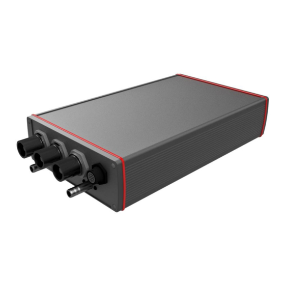
Page 8: Physical Description
HV-500 TECHNICAL DESCRIPTION (BETA VERSION) PHYSICAL DESCRIPTION Dimensions are shown in mm Revision 1.31... -
Page 9: Mounting Options
HV-500 TECHNICAL DESCRIPTION (BETA VERSION) Mounting options 4 X M4 screws Revision 1.31... -
Page 10: Connections
HV-500 TECHNICAL DESCRIPTION (BETA VERSION) CONNECTIONS Harness connector pinout (H) Connector type: TE CONNECTIVITY AMPSEAL 776228-1 Harness side connector type: TE CONNECTIVITY AMPSEAL 770680-1 16-20 AWG crimp pin type: TE CONNECTIVITY AMPSEAL 770520-1 12_VIN Auxiliary voltage plus, 9 V – 15 V maximum 30 W... -
Page 11: Motor Sensor Connector Pinout (M)
HV-500 TECHNICAL DESCRIPTION (BETA VERSION) Motor sensor connector pinout (M) Connector type: SOURIAU UTS712D14S32 Harness side connector type: SOURIAU UTS6JC12E14P B+ / Hall U ABI encoder „B” differential signal positive or A hall sensor ABI encoder „B” differential signal negative A+ / Hall V ABI encoder „A”... -
Page 12: Hall Sensors
HV-500 TECHNICAL DESCRIPTION (BETA VERSION) HALL SENSORS • Latching type Hall-effect sensors input • Maximum input signal voltage: 5 V • Maximum input frequency: 400 Khz High power connection CP-600 type custom made connector. 600 A peak load capacity. Female connector tightening torque: 5 Nm... -
Page 13: Pc Connection And Control
You can connect the inverter with a USB to RS-232 adapter (for example: ATEN UC232A) to the PC, where the inverter can be parameterized. Use the „H” connector 5. and 13. pins and ground to common potential. The DTI Tool software can be run on the PC. The DTI Tool compatible with windows 10 x86 or x64. -
Page 14: Harness Connector Wiring
HV-500 TECHNICAL DESCRIPTION (BETA VERSION) Harness connector wiring You must use a TE CONNECTIVITY connector parts. The harness side connector type: 770680-1 and the corresponding crimp pins: 770520-1 for 16-20 AWG wire A special hand crimp tool is required for crimping the pins: 58529-1 Try to create the simplest and shortest wiring harness as possible. -
Page 15: Input Supply
HV-500 TECHNICAL DESCRIPTION (BETA VERSION) INPUT SUPPLY ▪ Reverse polarity protection ▪ Overvoltage protection ▪ Resettable overcurrent protection ▪ Power supply: 9-15V ANALOG INPUT ▪ High frequency filter ▪ Overvoltage protection ▪ Maximum 5V input DIGITAL INPUT ▪ Button debounce ▪... -
Page 16: Rs 232 Pheriphery
HV-500 TECHNICAL DESCRIPTION (BETA VERSION) RS 232 PHERIPHERY ▪ ESD protection ▪ Internal serial transceiver Motor sensor connector wiring The motor sensor side connector type: Souriau UTS6JC12E14P. The wires must be soldered to the connector. Use a shrink tube for each wire to prevent a short circuit. -
Page 17: Hall Sensor
HV-500 TECHNICAL DESCRIPTION (BETA VERSION) HALL SENSOR Only connect the wires witch found in the sensor connection diagram. Leave the other pins free on the connector. The internal circuit contains the hall sensor pull up resistors. Hall sensor wiring diagram... -
Page 18: High Voltage Wiring
HV-500 TECHNICAL DESCRIPTION (BETA VERSION) High voltage wiring First of all, read "LIABILITY AND SAFE USE OF THIS UNIT". The wiring of the high voltage must be carried out by a specialist. Keep in mind that DC high voltage is very dangerous and deadly.
Need help?
Do you have a question about the HV-500 and is the answer not in the manual?
Questions and answers