Makita 6836 Technical Information
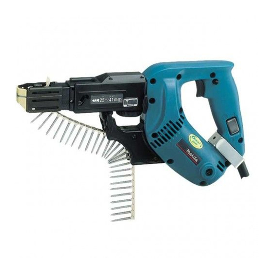
Auto feed screwdriver
Hide thumbs
Also See for 6836:
- Instruction manual (40 pages) ,
- Instruction manual (37 pages) ,
- Instruction manual (25 pages)
Advertisement
T
ECHNICAL INFORMATION
Models No.
Description
C
ONCEPT AND MAIN APPLICATIONS
Model 6836 has been developed as an upgraded sister tool to the current 6833.
Features high rotational speed of 6,000rpm for high operation efficiency while
less pressure is required on the tool to drive screws, reducing operator fatigue.
These two main advantages will allow operator to set more screws for one day
operation with less fatigue.
S
pecification
Voltage (V)
110
220
230
240
Driver bit: mm (")
Capacity: mm (")
[collated drywall screw]
No load speed: min.
Reverse switch
Protection against electric shock
Cord length: m (ft)
Net weight: kg (lbs)
S
tandard equipment
Philips bit 2-132 ......................... 2
Plastic carrying case ................... 1
Note: The standard equipment for the tool shown above may differ by country.
O
ptional accessories
Philips bit 2-132
Extension handle
6836
Auto Feed Screwdriver
Cycle (Hz)
Current (A)
4.3
50 / 60
2.3
50 / 60
2.2
50 / 60
2.1
50 / 60
Shank
Overall length
Diameter
Overall length
= rpm
-1
Continuous Rating (W)
Input
Output
470
220
470
220
470
220
470
220
6.35 (1/4) Hex
132 (5-3/16)
4 (5/32)
25 to 41 (1 to 1-5/8)
6,000
Yes
Double insulation
2.5 (8.2)
1.9 (4.2)
PRODUCT
P 1 / 7
L
W
Dimensions: mm (")
Length (L)
364 (14-3/8)
Width (W)
76 (3)
Height (H)
191 (7-1/2)
Max. Output(W)
400
400
400
400
H
Advertisement
Table of Contents

Related Manuals for Makita 6836


Summary of Contents for Makita 6836
- Page 1 Auto Feed Screwdriver ONCEPT AND MAIN APPLICATIONS Model 6836 has been developed as an upgraded sister tool to the current 6833. Features high rotational speed of 6,000rpm for high operation efficiency while less pressure is required on the tool to drive screws, reducing operator fatigue.
-
Page 2: Necessary Repairing Tools
1R280 Round Bar for Arbor 6-50 Removing Spiral bevel gear 15 [2] LUBRICATION Apply Makita grease to the following portions designated with the black triangle and gray triangle to protect parts and product from unusual abrasion. Item No. Description Portion to apply adhesive... - Page 3 P 3 / 7 epair [3] DISASSEMBLY/ASSEMBLY [3] -1. Disassembling/Assembling Feeder Box Assembly DISASSEMBLY 1) First, separate Casing assembly from Housing and Screw guide by unscrewing two M4x28 Thumb screws then pulling in the direction of the arrow. (Fig. 2) Fig.
- Page 4 P 4 / 7 epair [3] -1. Disassembling/Assembling Feeder Box Assembly (cont.) 2)-5. Remove Wheel together with Dust cover from Feeder box by levering up with a Phillips screwdriver inserted into the through hole of Dust cover. (Fig. 7) 2)-6. Remove Spur gear 16 and Pin 6. Then remove Sleeve 5 by levering up with a Phillips screwdriver inserted in the through hole of Sleeve 5.
- Page 5 P 5 / 7 epair [3] -1. Disassembling/Assembling Feeder Box Assembly (cont.) 2. Notes to Remember When Assembling Casing Assembly When assembling Casing (R) and (L) together, fit the protrusion Fig. 12 on Casing (L) to the groove on the back of Dial 42. (Fig. 12) Dial 42 See Fig.
-
Page 6: Installation
P 6 / 7 epair [3] -2. Removing/Installing Spiral Bevel Gear from/on Armature (cont.) 3) As illustrated in Fig. 14, Remove Spiral bevel gear 15 from Fig. 14 Armature using Bearing plate (No.1R022), Pipe ring (No.1R023), Ram of arbor Press Round bar 50 (No.1R280) and arbor press. -
Page 7: Circuit Diagram
P 7 / 7 ircuit diagram Color index of lead wires' sheath Black White Reversing Orange switch Choke coil Blue Purple Choke coil Brown Clear Noise suppressor Field Power supply Main cord switch Earth terminal iring diagram Main switch Put Noise suppressor here if used. Noise suppressor (if used) Reversing switch...
Need help?
Do you have a question about the 6836 and is the answer not in the manual?
Questions and answers