Table of Contents
Advertisement
Advertisement
Table of Contents

Related Manuals for Logika Technologies LM-SD

Summary of Contents for Logika Technologies LM-SD
- Page 1 Model LM-SD Standard Distance Laser Meter Operator’s Manual Version 11-2010...
-
Page 2: Table Of Contents
5.1 Controls ......................... 12 5.2 Setting Parameters ....................... 13 5.3 Parameter Menus ......................13 6. Maintenance ........................15 6.1 Regular Maintenance ....................15 6.2 Returns of the LM-SD ....................15 7. LM-SD Enclosure Dimensions ..................... 16 Web: www.logikatech.com Phone: 905-829-5841 Fax: 905-829-8787 Email: info@logikatech.com... -
Page 3: Introduction
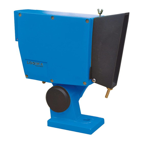
Rev. 11-2010 1. Introduction The LM-SD is a laser based distance measurement tool used to measure distances from 0.2m to more than 100m with pinpoint accuracy. A given target can be clearly identified with the help of a red laser sighting point. The usable range of the sensor is dependent upon target physical properties. -
Page 4: Description
Logika Technologies Inc. Model LM-SD Operator’s Manual Rev. 11-2010 2. Description 2.1 Model Nomenclature Record your Laser Meter’s complete Model Number here: LM-SD - ___________ Base Model Power Input 24: 24VDC 110: 110VAC Serial Number _________________ Figure 2.1: Model Number 2.2 Specifications... -
Page 5: Operating Principle
3. Location and Mounting 3.1 Sensor Location The LM-SD Sensor should be installed so as to give a direct view of the target, unobstructed by dust, steam, hoses or passers-by. The mounting should be vibration free, as any motion of the sensor is magnified many times at the laser spot. This is a Class II laser, it should mounted not to shine directly into the eyes of plant personnel. - Page 6 Logika Technologies Inc. Model LM-SD Operator’s Manual Rev. 11-2010 Figure 3.1 shows the zero point on the LM-SD for calibration purposes. There is a parameter “OF” that allows the Zero Point to be changed to some other meaningful point in space.
-
Page 7: Sensor Mounting
The sensor is fixed to the support with a single 18 mm bolt through the LM-SD’s base mounting stand. The altitude angle may be changed by slightly loosening the three cap screws in the base with a 4mm Allen key, adjusting to the correct angle and retightening the same three screws. -
Page 8: Utility Connections
4. Utility Connections 4.1 Electrical Connections Electrical Overview- All electrical connections (power and signal) to the LM-SD are made via a 15-pin Harting style connector with ground. The sensor is supplied with a mating connector at the back of its enclosure and a standard 2-meter cable with the quick-connect assembly mating to the sensor and bare wire terminals for the junction box connections. - Page 9 Logika Technologies Inc. Model LM-SD Operator’s Manual Rev. 11-2010 Figure 4.1 Connections to LM-SD Harting Connector Cable Specification- Multi-lead cables of 10 x 20 gauge (10 x 0.6 mm²) shielded Teflon insulation for high temperature applications. Outer metallic braid for mechanical protection.
- Page 10 Logika Technologies Inc. Model LM-SD Operator’s Manual Rev. 11-2010 Each lead is color-coded. Junction Box Wiring- Please see Figure 4.1 for the sensor wiring diagram. The supplied cable should be connected directly to the terminals of a junction box. All cables must be shielded all the way to the console with the shield connected to ground to eliminate electrical noise, which may trigger false detection.
-
Page 11: Plumbing Connection
Logika Technologies Inc. Model LM-SD Operator’s Manual Rev. 11-2010 4.2 Plumbing Connection Description- Water cooling is required when the ambient temperature at the sensor’s location is higher than 50 C (120 F). Temperatures above this level require protection for the electronics. - Page 12 Logika Technologies Inc. Model LM-SD Operator’s Manual Rev. 11-2010 Compressed Air Requirements Must be clean, dry air free of contaminants. Poor purge air quality will lead to dirty glass which may decrease sensor performance and increase sensor maintenance. Air filtration prior to the sensor purge inlet fitting is recommended for purge air of questionable quality.
-
Page 13: Operation
Rev. 11-2010 5 Operation 5.1 Controls The LM-SD Sensor’s Control Panel is located under the protective cover plate on the back of the sensor. The following functions are available at the Control Panel. Figure 5.1: Control Panel The five digit display shows the current reading in RUN mode and parameter information in SETUP mode. -
Page 14: Setting Parameters
Logika Technologies Inc. Model LM-SD Operator’s Manual Rev. 11-2010 5.2 Setting Parameters 1. Press and hold the REDUCE button for two seconds until SEL-0 is displayed. 2. Press ADD or RED to select the desired menu (See Section 5.3). In this example we will use SEL-3, Alarm Center. - Page 15 Logika Technologies Inc. Model LM-SD Operator’s Manual Rev. 11-2010 Default Value: 02.500m SEL4 – AH – Alarm Hysteresis: Width of the deadband on either side of the Alarm Center. This prevents flicker of the Alarm Outputs. Minimum Value: 00.000m Maximum Value: 99.999m...
-
Page 16: Maintenance
Lens Cleaning- Routinely check the LM-SD sensor’s glass for dust or oil residue. Open the lens shield board at the front of the sensor by unscrewing the fastening hardware on the shield and clean the glass with alcohol and lens paper or soft cloth. -
Page 17: Lm-Sd Enclosure Dimensions
Logika Technologies Inc. Model LM-SD Operator’s Manual Rev. 11-2010 7. LM-SD Enclosure Dimensions Figure 7.1: LM-SD Enclosure and Mounting Bracket Dimensions Web: www.logikatech.com Phone: 905-829-5841 Fax: 905-829-8787 Email: info@logikatech.com P a g e | 16...
Need help?
Do you have a question about the LM-SD and is the answer not in the manual?
Questions and answers