Table of Contents
Advertisement
OPERATING INSTRUCTIONS
COMMISSIONING / OPERATING / MAINTENANCE
(must be given to the end user in order to complete the operating manual during the equipment service life)
QUIETCO
OL
2
/ PED fluid group : 2
These operating instructions must be read at the delivery of the equipment and prior any operation on it.
Our technical department is at your disposal for any additional information (Tel : + 33 4 42 18 05 00).
This document is a translation of the French original version which prevails in all cases.
Version 9110
Advertisement
Table of Contents

Related Manuals for Profroid QuietCO2OL Series


Summary of Contents for Profroid QuietCO2OL Series
- Page 1 OPERATING INSTRUCTIONS COMMISSIONING / OPERATING / MAINTENANCE (must be given to the end user in order to complete the operating manual during the equipment service life) QUIETCO / PED fluid group : 2 These operating instructions must be read at the delivery of the equipment and prior any operation on it. Our technical department is at your disposal for any additional information (Tel : + 33 4 42 18 05 00).
- Page 2 The following table aggregates all the main modifications since the last version Modifications since the version N° 051217 Pages Instruction on the refrigerant charge Clarification on the system pressure (all the Addition of the water cooled units document) P 14 Addition of some remarks on transportation P 16 Warning concerning the mounting of the liquid lines...
-
Page 3: Table Of Contents
TABLE OF CONTENTS SAFETY GENERAL STARTUP INSTRUCTIONS CAUTION FOR SAFETY COMPONENTS SCOPE OF APPLICATION DIMENSIONS HANDLING OF THE UNIT SELECTION OF INSTALLATION LOCATION 13-14 REFRIGERANT PIPING WORK 15-16 COMMISSIONING 17-19 OPERATING REFRIGERANT CIRCUIT DIAGRAM 21-22 ELECTRICAL CONNECTIONS 23-24 USER INTERFACE 25-27 DESCRIPTION OF THE DISPLAY 28-29... -
Page 4: Safety
The contractor or the company in charge of the installation shall be responsible for carrying out the required instructions. Profroid disclaims any responsibility for change(s) or repair(s) on its devices made without its prior agreement. The devices are exclusively intended for professionals, for refrigeration purposes and for their limits of use. - Page 5 When operating, surface temperatures above 60°C and /or below 0°C may be reached. During any servicing operation, the personnel should be extremely careful while working on the device. Profroid is not informed to real use of partly completed machines ; their integrations and use must comply to Machines Directive and recommendations of this operating instructions.
-
Page 6: Safety
If there is modification of type and /or brand, then the professional in charge of the replacement will do a calculation sheet following EN 13136 and /or ask Profroid some elements. Handle regularly the device valves in view to avoid theirs blocking on. -
Page 7: General Startup Instructions
GENERAL STARTUP INSTRUCTIONS Vacuum To avoid inclusion of air or moisture in the refrigerant circuit, be sure to execute vacuum drying of the entire circuit before charging refrigerant by using a vacuum pump. Vacuum the circuit after securely carrying out airtight/pressure testing. >... - Page 8 GENERAL STARTUP INSTRUCTIONS Method of Charging – Use Manifold Gauges and charging hoses for CO only. – Use only refrigeration quality R744. – When charging the refrigerant fix the flexible to the frame to avoid any risks – Use a refrigerant scale to measure correct quantity charged into the system from the R744 cylinders.
-
Page 9: Caution For Safety
– If the installation, the commissioning, the operating, the maintenance are not realised according to this operating instructions, the responsibility of Profroid cannot be involved. – Completely inform the customer on the control, maintenance and follow-up of the refrigeration equipment. -
Page 10: Caution For Safety
CAUTION FOR SAFETY – Do not use other than the designated refrigerant (for charging, adding or recharging) – Refrigerant gas leak may cause suffocation. – Piping, equipment components and tools should be appropriate for use with R744 (CO2 refrigerant). – Use of unsuitable components or those designed for HFC refrigerant may cause serious incidents such as equipment failure and rupture of the refrigerant cycle. -
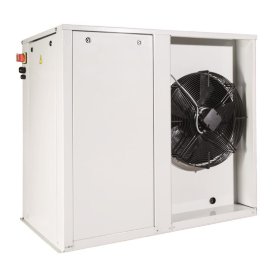
Page 11: Components
COMPONENTS QUIETCO OL air cooled : Electrical compartment MT Version Gas cooler EC3 Control valve intermediate pressure EC1 HP Control valve HP safety pressure switch LP/HP Pressure Shut-off valves liquid line transducer Compressor Service valve Suction line Service valve Filter drier liquid line Sight glass HP service valve... -
Page 12: Components
COMPONENTS QUIETCO OL water cooled : MT Version 3-ways valve EC3 Control valve By-pass valve (gas cooler) intermediate pressure Plate Heat Exchanger EC1 HP Control valve Sight glass Filter drier LP/HP Pressure transducer Compressor HP service valve Service valve liquid line Service valve suction line LT Versions Regulating thermostatic... -
Page 13: Scope Of Application
SCOPE OF APPLICATION Produit QUIETCO OL serie GMCC Toshiba Compressor model 50MT 30MT 67MT 100MT 75LT 167LT Refrigerant R744 PAG VG100 Oil(Supplier) PZ100S Alternative oil PAG100 FUCHS Evaporating -18°C à +5°C -32°C à -18°C temperature Suction 20K or below superheating Circuit du fluide Discharge... -
Page 14: Dimensions
DIMENSIONS Fig 1 Fig 2 Fig 3 Fig 4 Fig 5 Fig 6 QUIETCO2OL MT serie QUIETCO2OL LT QUIETCO2OL serie Air cooled Serie Air cooled Water cooled QC LT75 QC LT167 QC MT QC LT MT30 MT50 MT67 MT100 Fig 1 Fig 3 Fig 2 Fig 4... -
Page 15: Handling Of The Unit
HANDLING OF THE UNIT Carry-in Operation Make sure that the equipment or its accessories have not been damaged during shipping and no parts are missing. Carry the refrigeration unit gently by keeping the vertical position as much as possible. Absolutely avoid a lay-down position of the refrigeration unit. -
Page 16: Selection Of Installation Location
SELECTION OF INSTALLATION LOCATION The QUIETCO2OL Air Cooled is intended for outdoor installation 500 mm – The refrigeration unit must be installed with an inclination angle 1°or below. If devices are used in a seismic area, then the installer must apply all necessary rules. - Page 17 SELECTION OF INSTALLATION LOCATION NO air from a second unit shall be directed towards the gas cooler of another one! case face-to-face installation, keep a minimum of 2000mm distance between the units. 2000 mm Important: For transportation purpose the cable glands have been placed in reverse position.
-
Page 18: Refrigerant Piping Work
REFRIGERANT PIPING WORK Selection of Refrigerant Piping Size The connection piping size for refrigeration unit is, in principle, as shown below, but each installation should be determined by calculating pressure loss of the piping and refrigerant flow speed and making sure no problem occurs in the cooling capacity and oil return. -
Page 19: Refrigerant Piping Work
REFRIGERANT PIPING WORK Before any work is done on the refrigeration circuit, the holding charge must be removed. The piping used must be of copper refrigeration quality in accordance with PED 2014/68/EC and EN12735-1. All piping must be correctly supported and fixed and should in no case be allowed to restrict the operation of the gas cooler unit. -
Page 20: Commissioning
COMMISSIONING – Do not use other than the designated refrigerant (for charging, adding or recharging). – Prior to electrically connect the facility, make sure that the AC power line voltage and frequency ratings correspond to the indications on the identification plate and the power voltage is within a tolerance of + 10 % with respect to the rated value. - Page 21 COMMISSIONING The 3-ways valves on the water cooled version (WCO) are set from the factory. In case of replacement follow the procedure below: 1- Complete set Disassembly of the engine Unscrew the engine with the dedicated tool (control handle) 2- Check the valve position as indicated 3- Disengage the engine if necessary...
- Page 22 COMMISSIONING Thermostatic valve (water cooled version) After replacing it make sure to set the thermostatic valve according to the factory settings. Graduation 2.5T which correspond to a temperature of 45°C (CO...
-
Page 23: Operating
During any servicing operation, the personnel should be extremely careful while working on the device. – Profroid is not informed to real use of partly completed machines; their integrations and use must comply with Machines Directive and recommendations of these operating instructions. -
Page 24: Refrigerant Circuit Diagram
REFRIGERANT CIRCUIT DIAGRAM QUIETCO OL AIR COOLED : MT Version LT Version... - Page 25 REFRIGERANT CIRCUIT DIAGRAM QUIETCO2OL WATER COOLED VERSION : MT Version LT Version...
-
Page 26: Electrical Connections
ELECTRICAL CONNECTIONS Caution Electrical compartment contains live terminals, please ensure supply is isolated before removing the cover. Any person accessing this part of the unit should be suitably trained and competent. Before carrying out any maintenance work, disconnect the drive and the external control circuits from the power supply by moving the main system switch to “off”. - Page 27 ELECTRICAL CONNECTIONS Recommendation In order to ensure the optimal operation of the installation, we recommend the use of controller and expansion valves from Carel connected to the unit through a Modbus connection. When using other brands of controller or expansion valve, a special attention must be paid on the settings on site. Bad settings of these components can lead to an instability of the system, short cycling the compressor and oil return issue, endangering the condensing unit operation.
-
Page 28: User Interface
USER INTERFACE Types of display There are three fundamental types of display shown to the user: – Main display – Menu display – Screen for display/setting the parameters Remark : All images below are for reference only; the user interface can be changed without prior notice. Main display USER PASSWORD: 1502 The software on board pRack Hecu automatically returns to the main mask 5... - Page 29 USER INTERFACE Screen for displaying/setting the parameters An example of visual for displaying/setting the parameters is shown in the figure, also highlighting the fields and icons used: 1. Parameters 2. Screen identifier 3. Menu The display identifier details the menu branch and the mask: the first character indicates the menu branch, while the two alphanumeric digits identify the order of the mask inside the menu.
-
Page 30: User Interface
USER INTERFACE Navigation To navigate inside the menu tree, use the following buttons. -
Page 31: Description Of The Display
DESCRIPTION OF THE DISPLAY Menu tree Level 1 Level 2 Level 3 Description a. Main info Information of the different operational states A. Unit Status b. Setpoint Setpoint modification c. On/Off Regulation on/off a. Digital Inputs Configuration and status of the digital inputs b. -
Page 32: Description Of The Display
DESCRIPTION OF THE DISPLAY Menu tree Level 1 Level 2 Level 3 Description a. Thermostats Configuration up to 5 thermostats (digital outlets) b. Modulations Configuation up to 2 modulating thermostats (analog outlets) f. Generic c. Alarms Digital inlets alarms configuration functions d. -
Page 33: Manual Mode For The Vacuum Procedure
MANUAL MODE FOR VACUUM PROCEDURE Remark: All images below are for reference only; the user interface can be changed without prior notice. Main display Password management Insert password: user = 1502 Press enter to continue. Main menu Use arrows up/down to access the necessary masks. -
Page 34: Control Functions
CONTROL FUNCTIONS Protective functions – Compressors stops when: – High pressure exceeds 108 bar. – Restarts with manual reset. – Low pressure is below 15 bar. – Automatic reset. – BLDC Power + Alarm. See display information. Compressor auto reset. –... -
Page 35: Maintenance
If you clean up the unit with water a special attention must be paid on the electrical parts and on the gas cooler fins. Replacement parts The spare parts list is available on the QuietCO OL product page on www.profroid.com under the rubric "Associated documentation"... - Page 37 MAINTENANCE Défaut Cause probable Action requise Examine and adjust the thermostatic Too much suction gas superheat 1. Suction temperature too expansion valve in the evaportors (above 20 K) high Liquid in the suction line Adjust the thermostatic expansion valve 2. Suction Temperature too Check if the sensor is in contact with Sensor is loose or incorrectly the suction line and replace if...
- Page 38 MAINTENANCE Défaut Cause probable Action requise Bolts loose Tighten bolts Check and re-set the expansion valves. Check that the liquid solenoid Fluid in the suction 11. Abnormal noise in valves do not remain open when line the compressor machine stops The Discharge temperature sensor is not stable or badly Check sensor position...
-
Page 39: Warranty Conditions
WARRANTY CONDITIONS OF THE REFRIGERATION UNIT No charge warranty period is 1 year from the date of installation of the refrigeration unit. However, the coverage of the no-charge warranty is the failed component by supplying a replacement component. Any failure caused by the following reason is considered chargeable even during the warranty period. - Page 40 Manufactured in France by PROFROID CARRIER S.C.S 178, rue du Fauge - ZI Les Paluds - B.P. 1152 - 13782 Aubagne Cedex - France...
-
Page 41: Ecodesign
ECODESIGN Air cooled Version : Rated P SEPR Annual MT Evap. Temp. =-10°C SEPR Seasonal energy COP Validity electric. Rated COP LT Evap. Temp. =-32°C VALIDITY perfom. ratio consum. Amb. Temp. Ta= +32°C (kW) (kWh/a) MT30PK 2,71 6 974 1,76 MT50PK 4,10 10 608... -
Page 42: Appendix 1: Refrigerant And Oil Charge
APPENDIX 1 : REFRIGERANT AND OIL CHARGE This appendix gives the instructions for charging the unit with R744 and additional oil. The following assumptions have been made in order to calculate both charges: 90% filling factor for gascooler in partload. Min/Max level in receiver: 10% / 80%. - Page 43 APPENDIX 1 : REFRIGERANT AND OIL CHARGE AIR COOLED VERSION...
- Page 44 APPENDIX 1 : REFRIGERANT AND OIL CHARGE AIR COOLED VERSION...
- Page 45 APPENDIX 1 : REFRIGERANT AND OIL CHARGE WATER COOLED VERSION Evaporator volume (based on filling factor of 20%) Oil charge in kg Pipe length CO2 Charge in kg Evaporator volume (based on filling factor of 20%) Oil charge in kg Pipe length CO2 Charge in kg...
- Page 46 APPENDIX 1 : REFRIGERANT AND OIL CHARGE WATER COOLED VERSION Evaporator volume (based on filling factor of 20%) Oil charge in kg Pipe length CO2 Charge in kg Charge CO2 en kg Evaporator volume (based on filling factor of 20%) Oil charge in kg Pipe length CO2 Charge in kg...
-
Page 47: Appendix 2 : Alarm List
APPENDIX 2 : ALARM LIST Description écran Code Reset Delay Action ALU02 Regulation probe(s) missing Automatic Not present Shutdown unit ALA01 Discharge temperature probe broken or disconnected Automatic 60 s Related functions disabled ALA02 Gascooler pressure probe broken or disconnected Automatic 60 s Related functions disabled... - Page 48 APPENDIX 2 : ALARM LIST Not present ALW27 Envelope alarm Zone Semiautomatic Shutdown compressor ALW28 High discharge gas temperature Automatic 10 s ALW29 Low pressure differential (insuff. lubrication) Automatic Config. Shutdown compressor Not present ALW30 Inverter model not compatible (Power+ only allowed) Automatic Not present ALW35...
- Page 49 PROFROID CARRIER S.C.S 178, rue du Fauge - ZI Les Paluds - B.P. 1152 - 13782 Aubagne Cedex - France International : Tel. (33) 4 42 18 05 00 - Fax (33) 4 42 18 05 02...
Need help?
Do you have a question about the QuietCO2OL Series and is the answer not in the manual?
Questions and answers