Table of Contents
Advertisement
control –
motion
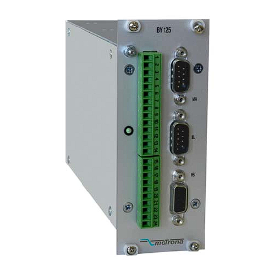
Low Cost Synchronous-Controller
Operating Instructions for Operator Software OS3.x
• 80 kHz counting frequency
• Highly dynamic response (120 μsec)
• Positional synchronization and ratio control
• Marker pulse and print mark registration
• Speed transitions by S-shape profile
• TTL encoder inputs
• Easy PC setting via serial link, data loading on the fly
• Simple to mount (rack or DIN rail)
• Standard version suitable for all 4-quadrant type drives with +/-10 V speed input
• Option UP125 especially suitable for 1-quadrant type inverter drives with positive
speed input only and digital direction select inputs
BY12512d_e.doc / Mai-08
– interface
BY 125
)
(
A, A, B, B, Z, Z
Operating Instructions
ELEKTRO-TRADING sp. z o.o
Tel.
+48 (0-32) 734-55-72
Tel/Fax +48 (0-32) 734-55-70
E-Mail et@elektro-trading.com.pl
http://www.elektro-trading.com.pl
Page 1 / 52
Advertisement
Table of Contents

Subscribe to Our Youtube Channel
Related Manuals for Motrona BY 125

Summary of Contents for Motrona BY 125
- Page 1 Tel/Fax +48 (0-32) 734-55-70 E-Mail et@elektro-trading.com.pl http://www.elektro-trading.com.pl control – motion – interface BY 125 Low Cost Synchronous-Controller Operating Instructions for Operator Software OS3.x • 80 kHz counting frequency • Highly dynamic response (120 μsec) • Positional synchronization and ratio control •...
- Page 2 Safety Instructions • This manual is an essential part of the unit and contains important hints about function, correct handling and commissioning. Non-observance can result in damage to the unit or the machine or even in injury to persons using the equipment! •...
-
Page 3: Table Of Contents
Table of Contents Introduction........................4 Principle of operation..................... 6 Impulse Scaling......................9 Ratio Change during Operation..................12 Change of Phase and Relative Position.................13 5.1. Timer Trimming (Modes 1 - 4 and 8)..................13 5.2. Impulse Trimming (Modes 5 and 6)....................13 5.3. Phase Offset Operation (Mode3)....................13 Index Control (Modes 2, 6 and 8) ..................14 Connections and Hardware Settings................16 7.1. -
Page 4: Introduction
Rack mounting of the cassette therefore does not require use of a swivel frame. Use of our SM 150 back plane (option) also allows easy DIN rail mounting. The BY 125 operates from an unstabilized 24 VDC supply (18 V... 30V). BY12512d_e.doc / Mai-08... - Page 5 Master Slave BT348 RS232/485 Miniterminal (Up to 32 axis) TX720 Operator terminal Possibilities for remote control PROFIBUS of a BY125 synchronizer When on the slave site you intend to use a 1-quadrant-type drive (speed reference always with positive polarity 0...+10 volts and digital forward/reverse select inputs), please refer to “Option UP125”...
-
Page 6: Principle Of Operation
2. Principle of operation All operation is based on setting an "analogue synchronization" between the drives first. This can be achieved by feeding a common speed reference voltage to the drives and tuning the drive speeds in order to get them into an approximate synchronism. A ratio adaptation may be necessary for the Slave drive, as shown in figure 1. - Page 7 The synchronizer continuously checks the two shaft positions and immediately responds by an analogue correction signal when an angular error starts to appear. This analogue correction, added to the slave’s reference with the correct polarity, will keep the shaft positions of Master and Slave in line.
- Page 8 The feed forward signal now is generated internally from the frequency of the master encoder and no external voltage must be applied to the analogue input. This allows the master drive to use internal ramps, because the encoder frequency always represents the real actual speed of the master.
-
Page 9: Impulse Scaling
3. Impulse Scaling Both, Master and Slave impulses can be scaled separately, for easy adaptation of the synchronizer to existing conditions (gear ratios, encoder resolution, roll diameters etc.). The scaling factor "Factor 1" provides impulse scaling for the Master channel and the scaling factor "Factor 2"... - Page 10 The following example should explain the calculations for Factor 1 and Factor 2 with a feed roll system, where the tension of the material should be varied remotely by adapting the slave speed: d=300 d=100 tension control Master Slave 1024 Imp./rev. 500 Imp./rev.
- Page 11 Hint 1: It is best, whenever possible, to have Factor 1 and Factor 2 in a numeric range of 0.1000 - 2.0000. This allows the BY to use the full 12 Bit resolution of all D/A converters. When, for example, the factor calculation results in figures like 4.5000 and 7.8000, it is better to set 0.4500 and 0.7800 (or 0.9000 and 1.5600 or any other proportional values within the recommended range) to ensure best operation.
-
Page 12: Ratio Change During Operation
4. Ratio Change during Operation The speed ratio can be changed at any time by changing Factor 1 via serial link. Changing Factor 1 from 1.0000 to 2.0000 will result in double slave speed. The speed transition can be sudden or soft. The slave approaches its new speed via an adjustable sin² ramp. See parameter "Ramp1". -
Page 13: Change Of Phase And Relative Position
5. Change of Phase and Relative Position The relative phase situation between Master and Slave is normally set by the state upon power-up or with the last Reset signal (with index modes, the index edges and the programmed phase displacement define the relative position, see chapter 6.) During all the operation, this initial phase condition is held without any errors, unless the operator uses one of the following facilities to change this condition 5.1. -
Page 14: Index Control (Modes 2, 6 And 8)
6. Index Control (Modes 2, 6 and 8) Index or marker pulses are used to automatically set the drives or the material into a correct relative position. It is possible to either use the zero pulse inputs on the encoder terminals (Z and /Z, 5 VTTL) or the index inputs on the screw terminals (10...30 V), and the parameter ”Index Mode”... - Page 15 As a special, the BY 125 can even operate with different number of marker pulses on both sides. This is possible due to the following features: a. The master index input is equipped with a programmable index divider, which, for example, allows sampling of only each fifth marker pulse.
-
Page 16: Connections And Hardware Settings
7. Connections and Hardware Settings Screw S1 (encoder settings) Master encoder 1 2 3 4 terminal (9-pos. male) strip Slave encoder (9-pos. male) S2 (RS 485 setting) (optional) Serial port (9-pos. female) Fig 8 Fig. 8 shows the connectors available on the front plate, Fig. 9 shows the block diagram of the unit with its minimum peripheral configuration and Fig. -
Page 17: Power Supply
The BY 125 operates from an unstabilized 24 VDC supply (+/- 25%); however, the voltage including ripple should not exceed the following limits (18 V...30 V). The supply of the BY 125 is electrically protected against wrong polarity misconnection by protection diodes. - Page 18 The 4-position DIL switch S1 allows the desired encoder voltages to be set. Correct switch settings are essential for proper function. See Fig. 8. • With encoders, supplied by the BY 125: Set positions 1 and 3 to "ON" (Master) Set positions 2 and 4 to "ON"...
-
Page 19: Analogue Input And Output
• For fully differential operation (RS422): Set positions 1 and 3 OFF (Master) Set positions 2 and 4 OFF (Slave) The inputs then operate in differential mode, which is best in terms of noise immunity. However, the impulse source must be of line driver type with external supply, when this input mode is used. - Page 20 It can be used for on-line operation with a master computer, a PLC or an operator terminal (e.g. BT348 or TX720 or other), accessing all registers and control functions. The serial communication protocol uses the Drivecom standard (ISO 1745), which is wide- spread in drive industry.
-
Page 21: Control Inputs And Outputs
1 2 3 4 5 6 7 8 Computer • When using RS485 transmission, the BY 125 needs time to switch from "transmit" to "receive" and the computer must provide a delay like shown in table 14 prior to the next serial access. - Page 22 (terminal 10) The BY 125 is out of operation for a time of 30 ms after activation of the store command and the Ready output will be low while storage is in progress.
- Page 23 Control Outputs: Ready This announces that the unit is ready to run. On power up, this output is (terminal 21) "Low" for about one second to allow the power supply to settle, and then switches to "High". The output goes low also for the duration of parameter storage to the EEPROM.
-
Page 24: Register List And Clarification
8. Register List and Clarification The register set is held on an EEPROM. The registers can only be programmed via serial link, using the RS232 or RS485 interface. The Software OS3.2 (included with delivery) allows easy downloading of complete register sets, reading, copying and editing the parameters. -
Page 25: General Parameters
8.1. General Parameters Menu Description Factor 1 Impulse scaling factor for the master encoder. Range 0.0001 - 9.9999 Factor 2 Impulse scaling factor for the slave encoder. Range 0.0001 - 9.9999. In modes 2, 6 and 8, this setting is automatically replaced by a fixed 1.0000 scaling Trim Time Rate of change of phase trimming, entered as number of software cycles (1 cycle = 100 μsec), when the +/- trim inputs are activated, or for Factor 1... - Page 26 Menu Description Ramp Ramp time for changes of speed ratio. Range 0 – 99.99 s. Setting Ramp to zero results in abrupt change of the slave speed. All other settings provide a sin² transition from one ratio to next within the preset time, independent of the difference between initial and final speed.
- Page 27 Menu Description Phase Adjust* Clarification: The setting depends on the dynamics of the drive and the maximum speed. If a marker pulse arrives every 20 ms but the drive cannot correct the largest error in 20msec, then it will lead to instability, if the next correction is performed before the previous is completed.
- Page 28 Menu Description Sampling Sets the internal f/V converter (digital feed forward control) with respect to Time dynamics and resolution. Setting is uncritical. Lower set values result in faster response, but less accuracy of the feed forward signal. Higher set values result in better accuracy, but slower response with sudden speed changes.
-
Page 29: Setup Registers
8.2. Setup Registers Menu Description Mode The mode setting determines the function of the Trim inputs and the Index inputs. There are 8 modes available like shown in the table below. Mode Trim inputs Index inputs Impulse scaling Phase trim by internal No Function Fact 1 : Fact 2 timer (additional speed) - Page 30 Menu Description LV- Calculation This parameter determines the relationship between the factor settings and the resulting slave speed. Also it selects analogue or digital feed forward operation. With settings 1 - 4, an analogue signal proportional to the master speed must be applied to terminal 16.
- Page 31 Menu Description Parameter LV-Calculation: Speed Ref Ref out (Master) (Slave) Setting 1-4 need analogue input proportional to master speed. Setting 5-8 generate VE by internal f/V converter Clarification: When LV - Calc is set to 1, the output voltage will be equal to the input voltage with Fact 1 = 1.0000 and Gain Tot = 1000.
- Page 32 Menu Description Ser- Form The following formats of serial data can be selected: Ser-Form Data bits Parity Stop bits even even None None Even None none Factory setting: = 0 Fig. 21 Mast Dir Direction of phase A/B of the master encoder. Setting 0 or 1. See commissioning.
-
Page 33: The Front Led
Menu Description Offset Total Not used. Set to 00 at any time. Gain Total Digital setting of multiplication of analogue voltage signal. Range 0 - 99999. With analogue feed forward, the output voltage is With digital feed forward, the output voltage is approximately where f r is the frequency of the master encoder in kHz. -
Page 34: Remarks About Drives, Encoders, Cables Etc
This ensures that the unit can use full analogue resolution. The BY 125 loads each encoder channel with a current of 6 mA. Though some encoder types are able to supply the impulse inputs of several synchronizers at a time, we recommend using an appropriate impulse splitter (e.g. -
Page 35: Screening
Where you use one common encoder for feedback of the drive and feedback for the BY125 at the same time, there may come up interference problems. You can use an impulse splitter to eliminate any kind of problems. In some applications, the common encoder would also work fine when it is supplied by the drive and the BY125 operates in fully differential mode like shown. - Page 36 The cross section of encoder cables must be chosen with consideration of voltage drop on the line. The BY 125 provides a 5.5 V encoder supply and at the other end the encoder must at least receive its minimum supply voltage! (See encoder specifications).
-
Page 37: Cables
10.4. Cables All cables should be installed separately from motor cables and other power lines. Use normal filtering methods for all inductive equipment installed close to the synchronizer (i.e. RC filters for AC contactors and diodes for DC inductive circuits). Take all standard precautions with respect to wiring and environment conditions that are usual for industrial electronic equipment. -
Page 38: Steps For Commissioning
11. Steps for Commissioning Make sure that the drives are properly adjusted to run the speeds needed for later synchronization. When using analogue feed forward, the internal acceleration ramps of Master and Slave must be set to minimum. With digital feed forward, the Master may use internal ramps, but the Slave ramps must be set to zero or minimum. - Page 39 • Start the OS3.0 operator software. You must see the following main screen now. Where you find an empty mask with the indication ”OFFLINE”. click to the Comms menu and verify the serial settings. Ex factory, the BY125 is set like shown below and you must set the COM number of your PC which you use for communication.
- Page 40 Where you do not know the actual settings of your BY125 unit, you can use the SCAN function in the Tools menu to find out. • When serial communication is o.k., enter all variables according to your application. The following registers must be set to fixed values for the first steps of commissioning, like shown in table.
- Page 41 Where you find letters undersigned, you can get the same function also by keypad, pressing Alt and the corresponding key (ex. Alt + S = Store EEprom • It is recommendable to check the correct function of the external control signals you have connected to the unit.
- Page 42 Select the Test function of the Tools menu • Click to the ”Master Direction” box and you will find an up/down counter for the master encoder. This counter must count up (increment) when you rotate the master encoder forward. When we count down, click ”Change direction” to reverse the counting sense. When we count up, change over to the ”Direction Slave”...
- Page 43 When, in final operation, we do not use one of the Index operation modes, we can exit the Test Menu now. Where Index functions will be needed later, click to the ”Master Index” and the ”Slave Index” boxes to execute the following tests: •...
- Page 44 • Enable both, Master and Slave drive and run the Master forward at slow speed (e.g. 10-20% of max. speed). The Slave will follow the Master. • Set the DIFFERENTIAL COUNTER to zero and the Color bar graph to the green centre by switching Reset to ON.
-
Page 45: Hints For Final Operation
12. Hints for Final Operation 12.1. Integrator When, for stability reasons, you needed to keep your ”Gain Correction” value low, any important non linearity in your drive system could cause changing phase errors* with changing speed (e.g. color bar deviates to right at low speed, stays in centre at medium speed and deviates to left at maximum, speed). -
Page 46: Other Settings
12.4. Other settings Up to now we have been operating in mode 1 with a couple of initial settings, in order to make commissioning easier. You are free now to set all variables to their final values, like required for your application. 12.5. -
Page 47: Serial Codes
13. Serial Codes Beside the serial access codes shown in this manual, the subsequent codes are available to execute the same commands that can be activated by the hardware inputs also: Ser. Code Bit of control word(C86) Function Type Reset Index Slave Index Master Trim -... -
Page 48: Master Reset And Eeprom Erasure
14. Master Reset and EEPROM Erasure The unit carefully checks all entry data for validity and correctness within their permitted numeric range. If, as an extreme exception, invalid data should intrude into the register range, bad function or even a full hang-up could be the result. If this should ever happen •... -
Page 49: Dimensions And Specifications
15. Dimensions and Specifications 122,5 30,5 Rear view 50,5 Front view Side view 50,5 Top view Power supply 18...30 V unstabilized Consumption approx. 200 mA (plus 25 % of the encoder supply currents, if internal encoder supply used) Encoder Supply Aux. -
Page 50: Appendix: Option Up125
16. Appendix: Option UP125 All previous remarks and hints are valid for drives accepting a +/- 10 volts speed input signal, where the direction of rotation depends on the polarity of the input voltage. However, many of the standard AC inverter drives offer only a positive input range, and the direction of rotation is selected by means of two digital inputs (“Forward enable”... - Page 51 Digital GND* Dotted connections are valid when the internal 24 volts of the BY 125 are used to drive the direction outputs In the menu, instead of register “Index Window” you will find the register “Dead Band”. This register provides proper control of the Forward and Reverse direction outputs as follows: •...
- Page 52 Hint: Most of the inverter drives would have an analogue dead zone near zero. This means they would not start to move with small voltage, but only break off when we overpass a certain minimum threshold (e.g. 100 mV) Speed (RPM) Analogue signal ”dead zone”...
Need help?
Do you have a question about the BY 125 and is the answer not in the manual?
Questions and answers