Table of Contents
Advertisement
Getting Started with the LX-1000 Series
MRV Communications, Inc. Corporate Center
MRV America Sales
295 Foster Street
Littleton, MA 01460
Tel: 800-338-5316 (U.S.)
Email: sales@mrv.com
Corporate Headquarters
20415 Nordhoff Street
Chatsworth, CA 91311
Tel: 818-773-0900
Fax: 818-773-0906
www.mrv.com
(Internet)
MRV Americas Service and Support
295 Foster Street
Littleton, MA 01460
Tel: 800-435-7997
Tel: +001 978-952-4888 (Outside U.S.)
Email: service@mrv.com
MRV International Sales
Business Park Moerfelden
Waldeckerstrasse 13
64546 Moerfelden-Walldorf
Germany
Tel: (49) 6105/2070
Fax: (49) 6105/207-100
Email: sales@mrv.com
451-0320H
Advertisement
Table of Contents

Related Manuals for MRV LX-1000 Series

Summary of Contents for MRV LX-1000 Series
- Page 1 Getting Started with the LX-1000 Series Corporate Headquarters MRV Communications, Inc. Corporate Center 20415 Nordhoff Street Chatsworth, CA 91311 Tel: 818-773-0900 Fax: 818-773-0906 www.mrv.com (Internet) MRV Americas Service and Support 295 Foster Street Littleton, MA 01460 Tel: 800-435-7997 Tel: +001 978-952-4888 (Outside U.S.) Email: service@mrv.com...
- Page 2 All rights reserved. No part of this publication may be reproduced without the prior written consent of MRV Communications, Inc. The information in this document is subject to change without notice and should not be construed as a commitment by MRV Communications, Inc. MRV Communications, Inc.
- Page 3 3 dBi for 1900 MHz operations and -0.5 dB for 850 MHz operations. EXPORT NOTICE MRV models contain 128-bit encryption software. Export of this product is restricted under U.S. law. Information is available from the U.S. Department of Commerce, Bureau of Export Administration at www.bxa.doc.gov.
- Page 4 451-0320 MRV Communications, Inc. www.mrv.com...
-
Page 5: Table Of Contents
Configure Mode ..........................37 Menu Mode ............................ 38 Software Upgrades..........................39 IP Configuration Menu ........................39 Booting from Defaults ........................39 Accessing and Configuring Additional Features ................39 Connecting to the LX-1000 Series via Telnet or SSH ..............39 451-0320 MRV Communications, Inc. www.mrv.com... - Page 6 Accessing from a Terminal Attached to an LX-1000 Series Serial Port ........40 Additional Considerations .........................40 Command Line Interface (CLI) Tree Structure................41 Additional Considerations for an Internet Environment ..............42 Autobauding Feature .........................42 Reinitializing/Powering Off the Unit ....................42 Alternative Port Capabilities ....................43 Sensor (Temperature/Humidity) Ports .....................43...
- Page 7 10/100 Connector Assignments ....................60 Adapter Wiring, LX-1000 Series to DTE ................... 62 Adapter Wiring, RJ-45 to DB-9, LX-1000 Series to DTE............63 Adapter Wiring, LX-1000 Series to DCE ................... 64 Modular Cables for RTS/CTS Flow Control (Eight-Wire), Concurrent with Modem Control Sig- nalling ............................
- Page 8 451-0320 MRV Communications, Inc. www.mrv.com...
- Page 9 Tables LX-1000 Series Specifications ....................51 Temperature/Humidity Sensor Specifications ................53 LX-1000 Series Factory Defaults ....................55 POST Test Error Codes ......................57 451-0320 MRV Communications, Inc. www.mrv.com...
- Page 10 451-0320 MRV Communications, Inc. www.mrv.com...
-
Page 11: Preface
Chapter 1 – Provides an overview of the LX-1000 Series, including supported communication speeds, software requirements, and conventions. • Chapter 2 – Describes how to install and connect the LX-1000 Series, as well as the unit’s LEDs and connectors. •... -
Page 12: Other Documentation
Management Information Base (MIB) structure (as pointers to objects in the devices) to manage these units. • Software Release Notes - Cites supported features as well as any notes and restrictions for the current software version. 451-0320 MRV Communications, Inc. www.mrv.com... -
Page 13: Overview Of The Lx-1000 Series
The LX-1000 Series includes the most comprehensive security features, such as per port access protection, TACACS+, SecurID, RADIUS, Secure Shell v2.0, PPP PAP/CHAP, PPP dial-back, on- board database, menus, and others. -
Page 14: Conventions
Overview of the LX-1000 Series Conventions The following conventions are used throughout this guide: • User prompt – The user prompt is (for example) InReach:0> for Non-superusers or InReach:0>> for superusers. The prompt will change based on a login user profile, as configured by the Superuser. -
Page 15: System Specifications
Overview of the LX-1000 Series System Specifications The following table lists important system specifications: Item Description Interface DTE RS-232 - RJ-45 Serial Line Speed 134.5 bps to 230 Kbps Ethernet Interface 10/100 Auto Sensing Default Serial Line Speed 9600 bps 451-0320 MRV Communications, Inc. - Page 16 Overview of the LX-1000 Series 451-0320 MRV Communications, Inc. www.mrv.com...
-
Page 17: Installing The Lx-1000 Series
Chapter 2 Installing the LX-1000 Series Hardware Installation This section explains how to install an LX-1000 Series Communications server and place it into operation. Unpack and Inspect the Unit Place all packing materials back into the shipping carton and save the carton. (If you need to return the unit to MRV or your distributor, you should return it in the original carton.) -
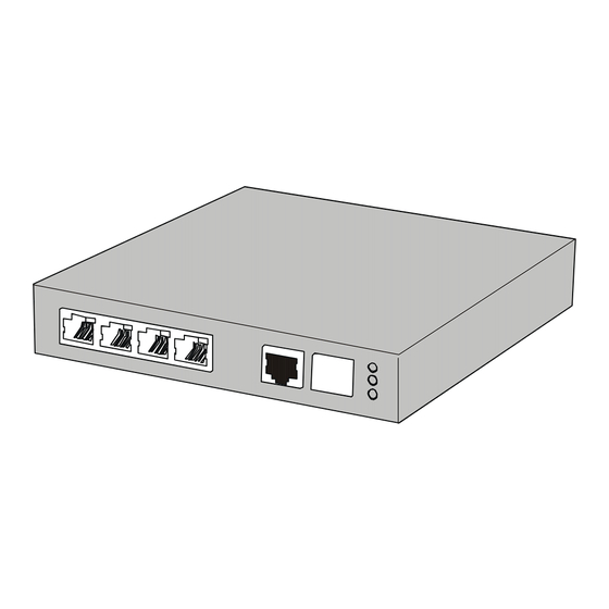
Page 18: Lx Indicators And Interfaces
LINK FLT LED (Fault) Port Status LEDs OK LED (System OK) 100 Mbps LED Port 1/ AUX Port 10/100 TX Figure 1 - LX-1000 Series 1- and 2-Port Front Panel MODEM Port LINK STATUS (optional) LEDs FLT LED (Fault) OK LED (System OK) -
Page 19: Lx-1000 Front Panel With Cellular Dual Band Antenna Interface
Installing the LX-1000 Series GSM/GPRS Cellular Dual Band Antenna Interface STATUS LINK LEDs FLT LED (Fault) OK LED (System OK) 100 Mbps LED DIAG/MGMT 10/100 TX Serial Port Ports 1-4 Figure 4 - LX-1000 Front Panel with Cellular Dual Band Antenna Interface... -
Page 20: Rear Panel
Installing the LX-1000 Series Rear Panel This section explains the rear panel and shows you a rear view of the LX-1000 series (see Figure 5 and Figure 6). DIAG/MGMT Port (Port 0) Power Connector 1A +5V DC Only (Center Pin Positive) -
Page 21: Rack Mount
You can rack mount the LX-1000 to the side of the rack or to the front of the rack. Attach the brackets to the unit, and then mount the unit in the rack. Refer to Figure 7 and Figure 8 for further information. Figure 7 - Side-Mounting an LX-1000 Series in a Rack 451-0320 MRV Communications, Inc. -
Page 22: Front-Mounting An Lx-1000 Series In A Rack
Installing the LX-1000 Series Figure 8 - Front-Mounting an LX-1000 Series in a Rack 451-0320 MRV Communications, Inc. www.mrv.com... -
Page 23: Wall Mount
Attach the brackets to the unit, and then mount the unit on the wall. Refer to Figure 9 for further information. Figure 9 - Mounting the LX-1000 Series on a Wall Desk Top Mount Attach the four rubber feet to the bottom of the unit, and then place the unit on a flat surface. -
Page 24: Cable Connections
Installing the LX-1000 Series Cable Connections This section explains the cable connections for the LX unit. Connect the Power Cable Connect the supplied power supply cable to the DC power connector on the rear of the LX unit and plug the other end into a wall outlet. The outlet type depends on which adapter cable you have. The North American adapter cable is a standard 2-prong connector (see Figure 10). -
Page 25: International Adapter Cable
Installing the LX-1000 Series Figure 11 - International Adapter Cable To remove a plug-in connector, press the push-down tab and slide the connector up and out of the slot. 451-0320 MRV Communications, Inc. www.mrv.com... -
Page 26: Connecting The Ethernet Interface
Connect a category 3 (CAT 3) cable for 10 Mbps operation, or a category 5 (CAT 5) cable for 10/100 Mbps operation to the 10/100 connector on the rear of the LX-1000 Series (see Figure 5) and the other end to your network. The LINK LED comes on steady green if the cable is properly connected. -
Page 27: Connecting Sfp Cabling
V.90/K56flex Kbps Modem Port The modem port is a V.90/K56flex Kbps optional factory installed modem on the LX-1000 Series. The modem port allows you to dial back from, or dial in to or out of the LX-1000. If the modem is present, connect your phone line to the modem’s RJ11 connector. -
Page 28: Connecting The Cellular Dual Band Antenna
Installing the LX-1000 Series Global System for Mobile Communications (GSM) is a voice service that can provide Circuit Switched Data connections with a maximum bit rate of 14.4 Kbps. General Packet Radio Service (GPRS) is a non-voice service that can provide data connections with a maximum bit rate of 115 Kbps. The actual data rates vary depending on the type of agreement you enter with your service provider and local RF related conditions. -
Page 29: Gsm/Gprs Signal Strength
Powering On The Power On Self Test (POST) starts when you apply power to the LX-1000 Series unit. At any time, POST status and failures are displayed on the management station. The POST test also detects whether you have a V.90 or GSM/GPRS Modem, or no modem at all. -
Page 30: Restarting The Unit
You can restart the LX-1000 Series using the following methods: Locate the power strip that the LX-1000 Series AC adapter is connected to and use the power strip On/Off switch to toggle the power to the LX-1000 Series device off. Wait at least 10 seconds before repowering the unit. -
Page 31: Configuring The Lx-1000 Series For The First Time
Chapter 3 Configuring the LX-1000 Series for the First Time Configuring the LX Unit for the First Time You can choose from five options to configure the unit for the first time: • First Time Configuration Utility - The first time an LX unit boots up at default parameters, you are presented with the option to run the Initial Connectivity setup. - Page 32 Configuring the LX-1000 Series for the First Time 1. Plug in the terminal at the DIAG/MGMT port (port 0 - port values are 9600 bps, eight data bits, one stop bit, no parity, and Xon/Xoff flow control). The Main Menu appears.
-
Page 33: Assigning An Ip Address Via The Network
Commands Reference Guide for information on specific commands. • To use Telnet, refer to “Connecting to the LX-1000 Series via Telnet or SSH” on page 39. • To use the web browser, refer to “Accessing and Configuring the Graphical User Interface (GUI)”... -
Page 34: Manually Setting The Ip Address Via The Cli
PC with Java Runtime Environment (JRE) release 1.4.2 or later installed. NOTE: For optimum GUI performance, MRV recommends that your PC run at 500 MHz or better. The minimum requirement for desktop color settings is 256. The GUI has two modes: Configuration and Menu. The one you can access depends on what privileges the administrator has given you. - Page 35 Configuring the LX-1000 Series for the First Time 1. At your browser, type the IP address of your LX unit. The LX Series Console page appears. NOTE: Make sure that your PC has access to the World Wide Web. You may need to download the latest release of the Java plug in to your PC.
- Page 36 Configuring the LX-1000 Series for the First Time 5. When your browser connects to the LX, the Java Security Warning window appears. NOTE: Your Java Security Warning window may vary, depending on your PC operating system. 6. Click on Grant this session. The Java Security Warning window closes. The LX Series Console page reappears, now with the green console selection visible.
-
Page 37: Configure Mode
Configuring the LX-1000 Series for the First Time NOTE: By default, authentication is done against the LX local user database. To start, use the known username InReach and password access. When you login, the next screen that appears depends on which mode you are authorized to configure and monitor. -
Page 38: Menu Mode
Configuring the LX-1000 Series for the First Time 3. Click on the menus on the left side of the window. For example, selecting Ports: Async opens the Async ports window: Menu Mode If you have access to the Menu Mode, the following screen appears when you login. Click on the various menu items on the left side of the window to perform preconfigured menu option tasks. -
Page 39: Software Upgrades
Series Configuration Guide. Accessing and Configuring Additional Features The following sections describe additional LX features you can access and configure. Connecting to the LX-1000 Series via Telnet or SSH Telnet Directly into the Communication Server NOTE: The default telnet port is 23. The default SSH port is 22. -
Page 40: Accessing From A Terminal Attached To An Lx-1000 Series Serial Port
Use the following procedure to access the command line interface port from a dumb terminal attached to an LX-1000 Series serial port, which is set for access local, or dynamic: 1. Hit the return key several times to autobaud (if autobaud is enabled) the port and get the Login: prompt. -
Page 41: Command Line Interface (Cli) Tree Structure
Configuring the LX-1000 Series for the First Time Command Line Interface (CLI) Tree Structure The command line interface structure is designed to be as intuitive as possible. Refer to “Navigating the LX Command Line Interface (CLI)” in the LX-Series Commands Reference Guide for detailed information on the command structure modes. -
Page 42: Additional Considerations For An Internet Environment
Configuring the LX-1000 Series for the First Time Additional Considerations for an Internet Environment If you plan to use the unit in an Internet environment, you must define addressing and identification characteristics to enable Internet hosts to recognize the unit as a member of the network. Using ppciboot, an LX-Series unit can be configured to obtain an IP address and other parameter values from the network when the unit boots. -
Page 43: Alternative Port Capabilities
Sensor provides accurate measurement of the temperature/humidity in the area in which your LX-1000 Series unit is placed. The following section explains how to connect and install the sensor. Connecting the Temperature/Humidity Sensor A 10-foot Male RJ-45 to Male RJ-45 straight-through cable (P/N MX-151-3027) connects the temperature/humidity sensor to the LX-1000 1/AUX port on the one or two port models, and ports 1-4 on the 4-port LX. -
Page 44: Ir-5150 Power Strip Management
30A, and for 208-240VAC up to 30A (Continental Europe). An IR-5150 Series offers individual remote control over the power on/off status to a maximum of 16 devices. The following section explains how to connect and install the IR-5150. 451-0320 MRV Communications, Inc. www.mrv.com... -
Page 45: Connecting The Ir-5150
RJ45 to RJ45 crossover cable and RJ45 to DB9F serial port adapter as required. See the Technical Specifications in Getting Started with the MRV Communications 5150 Power Control Series for more information on the RS-232 serial port. -
Page 46: Ir-4800 Power Strip Management
RJ45 to RJ45 crossover cable and RJ45 to DB9F serial port adapter as required. See the Technical Specifications in Getting Started with the MRV Communications 4800 Power Control Series for more information on the RS-232 serial port. -
Page 47: Using Lx Ports As Alarm Inputs And Control Outputs
Alarm Inputs - LX-Series port input signals DSR and CTS used in conjunction with the Signal- Notice software feature to monitor real world events. • Alarm Points - High impedance, low current, isolated inputs available in the MRV Corporation IR-7104 product. •... -
Page 48: Control Output Setup And Usage
An example circuit is shown in Figure 19. Important design issues to remember are: • Special design attention is required when using Control Outputs in a control subsystem. 451-0320 MRV Communications, Inc. www.mrv.com... -
Page 49: Typical Interface Design For Control Output Signals
• A common Signal Ground is required. • The MRV Corporation IR-7104 family can provide true Form C SPDT Relay outputs rated to 30VDC/1A per contact if higher capacity and stable contacts are required through restart and power cycles. Figure 19 - Typical Interface Design for Control Output Signals You must change the LX-Series port access type to control to utilize DTR and RTS as the Control Outputs. - Page 50 Alternative Port Capabilities 451-0320 MRV Communications, Inc. www.mrv.com...
-
Page 51: Appendix A -Technical Specifications
Appendix A -Technical Specifications The following table provides the specifications for the LX-1000 Series. Table 1 - LX-1000 Series Specifications Item Description Terminal Signals Transmit Data, Receive Data, Signal Ground, Data Set Ready/Data Car- rier Detect (DSR/DCD), Data Terminal Ready (DTR), Clear-to-Send (CTS), and Request-to-Send (RTS). - Page 52 Appendix A -Technical Specifications Dimensions LX-1000 Series 2-Port: LX-1000 Series 4-Port: Height 2.54 cm (1 in) 2.79 cm (1.1 in) Depth 15.8 cm (6.25 in) 15.8 cm (6.25 in) Width 10.7 cm (4.25 in) 15.01 cm (5.91 in) Weight LX 1000 2-Port - 0.4082 kg (0.9 lbs.) LX-1000 4-port - 0.66 kg (1.45 lbs)
- Page 53 0 to 70 deg. C (+32 to 158 deg. F) 5 to 90% humidity non-condensing ment Dimensions Height: 0.8 inches Length: 3.15 inches Width: 1.57 inches Weight 1.2 oz Accuracy Temp: +/-3 deg C Humidity: +/- 5% 451-0320 MRV Communications, Inc. www.mrv.com...
- Page 54 Appendix A -Technical Specifications 451-0320 MRV Communications, Inc. www.mrv.com...
-
Page 55: Appendix B - Factory Defaults
Appendix B - Factory Defaults The following table provides the factory defaults for the LX-1000 Series. Table 3 - LX-1000 Series Factory Defaults Item Description DIAG/MGMT Port/local management port The DIAG/MGMT port (port 0) is the console (default settings) management port. -
Page 56: Ppciboot Factory Default Settings
For defaults on specific commands, refer to the LX-Series Commands Reference Guide. Each LX-1000 Series unit is configured at the factory to use a default set of initialization parameters that sets all ports to operate with asynchronous ASCII terminal devices. -
Page 57: Appendix C - Post Test Error Codes
To view the error codes, connect a terminal to the DIAG/MGMT port. The error codes appear on the screen during a reboot. Error Code Definitions The following table provides the definitions for the LX-1000 Series POST test error codes. Table 4 - POST Test Error Codes Error Definition... - Page 58 Fast Ethernet Controller (FEC) Reception Failed Timeout 3030 Fast Ethernet Controller (FEC) Invalid Data Received 3040 Memory Error at (printing address) 5010 Memory Data Bus Failed 5020 Memory Address Bus Failed High 5030 Memory Address Bus Failed Low 5040 451-0320 MRV Communications, Inc. www.mrv.com...
-
Page 59: Appendix D - Cabling The Lx-1000 Series
Appendix D - Cabling the LX-1000 Series Cabling Considerations Standard cabling items available from MRV allow you to connect to any serial device that uses male or female DB-25 or DB-9 connectors. All you need is the appropriate cable (crossover cable for... -
Page 60: 10/100 Connector
- Voltage Figure 21 - 10/100 Connector Assignments Ordering Cables MRV also supplies crossover cables and modular adapters for use with all LX-1000 Series units. To order cables, adapters or other cabling accessories from MRV, contact your Sales representative or distributor. -
Page 61: Modem Control/Hardware Flow Control
Figure 24 illustrates RTS/CTS flow control for a DB-25 connector on a DCE device like a modem. LX-1000 Series serial ports can also be set up to support modem control (except for the DIAG/ MGMT port (port 0)). Figure 22, Figure 23, and Figure 24 support modem control as needed. Only Figure 23 and Figure 24 support concurrent modem control and RTS/CTS flow control between the LX Serial Port and the attached device. -
Page 62: Modular Adapters (Rj-45 To Db-25)
Appendix D - Cabling the LX-1000 Series Modular Adapters (RJ-45 to DB-25) You can obtain adapters with male and female DB-25 connectors from MRV. These adapters direct signals from the RJ-45 connector on the cable to the correct pin on the DB-25 connector. Figure 22, Figure 23, and Figure 24 show how devices are cabled when you use these adapters. -
Page 63: Adapter Wiring, Rj-45 To Db-9, Lx-1000 Series To Dte
XMTGND RCVGND DSR * Crossover Cable MX-151-3028 Adaptor Wiring - MX-350-0181 0308 (See Note, Page 5.) (Female RJ-45 to female DB-25) Male DB-9) Figure 23 - Adapter Wiring, RJ-45 to DB-9, LX-1000 Series to DTE 451-0320 MRV Communications, Inc. www.mrv.com... -
Page 64: Adapter Wiring, Lx-1000 Series To Dce
When a DTE device is connected to an LX-1000 Series serial port, the device's DTR output is connected to pin 7 of the LX-1000 Series. In this case, the signal at pin 7 is referred to as DSR. (This cabling scheme also provides DECconnect compatibility, since DECconnect does not support the DCD signal.) -
Page 65: Mrv 8-Wire Cabling
Appendix D - Cabling the LX-1000 Series MRV 8-Wire Cabling This cabling scheme provides XMT, RCV, DCD/DSR, DTR, RTS, CTS, and two signal ground wires. This cabling is provided through RJ-45 connectors. Using this cabling scheme you can concurrently use modem control and RTS/CTS hardware flow control, since there are four control signals. This scheme is useful with relatively high speed devices, complex modem control applications. - Page 66 Appendix D - Cabling the LX-1000 Series 451-0320 MRV Communications, Inc. www.mrv.com...
-
Page 67: Appendix E - Installing Sim Cards
1. Unplug the LX-1000 if you have not already done so. It is not necessary to remove the serial cables and Ethernet cable. If the LX-1000 is mounted in a rack, remove it from the rack. 2. Set the LX-1000 on a grounded workbench or other flat, stable surface. 451-0320 MRV Communications, Inc. www.mrv.com... -
Page 68: Removing The Cover
LX-1000 after you remove the cover. 4. Remove the screws that secure the cover on the LX-1000, using a Phillips-head screwdriver. Put the screws in a safe place. Then, lift and remove the cover. Figure 26 - Removing the Cover 451-0320 MRV Communications, Inc. www.mrv.com... -
Page 69: Installing A Sim Card
Set up the software per your Internet Service Provider’s requirements. NOTE: You need to configure the internal modem for dial-out. Refer to the “Internal Modem” chapter in the LX-Series Configuration Guide for further information. 451-0320 MRV Communications, Inc. www.mrv.com... - Page 70 Appendix E - Installing SIM Cards 451-0320 MRV Communications, Inc. www.mrv.com...
- Page 71 DB-25 connectors 62 DB-25 pin assignments 64 desk-mounting the unit 23 Java diagnostic port connector 59 installing 35 DTE devices connecting to LX-1000 Series 64 DTE wiring 62 fault 19 link 19 environment 20 OK 19 environmental considerations 20 receive 19...
- Page 72 LX-1000 Series 2-port rear panel 20 RJ-45 jacks 26 LX-1000 Series 4-port rear panel 20 RJ-45 wiring 61 LX-1000 Series 4-port rear panel with SFP slot 18 LX-1000 Series serial ports sensor ports 43 number of 51 serial device cables...
- Page 73 INDEX interface 53 weight 53 viewing error codes 57 tie-wrap strain relief 26 typographical conventions 14 wall-mounting the unit 23 wiring schemes Unpacking and inspecting the unit 17 for RJ-45 61 451-0320 MRV Communications, Inc. www.mrv.com...
Need help?
Do you have a question about the LX-1000 Series and is the answer not in the manual?
Questions and answers