Table of Contents
Advertisement
Quick Links
I
IMPORTAR
The ORION Fixed Network Gateway Installation Form (ORI-FM-03106-EN) must be completed for each
installation and returned to Badger Meter. The form is available in the Resource Library at www.badgermeter.com.
POI-UI-02543-EA-02 (June 2019)
POIPA® Fixed Aetwork (SE)
Gateway Rransceiver with Cellular LRE Backhaul
Installation Ianual
Advertisement
Table of Contents

Related Manuals for Badger Meter ORION Fixed Network


Summary of Contents for Badger Meter ORION Fixed Network
- Page 1 Gateway Rransceiver with Cellular LRE Backhaul IMPORTAR The ORION Fixed Network Gateway Installation Form (ORI-FM-03106-EN) must be completed for each installation and returned to Badger Meter. The form is available in the Resource Library at www.badgermeter.com. Installation Ianual POI-UI-02543-EA-02 (June 2019)
-
Page 2: Table Of Contents
ORION® Fixed Network (SE), Gateway Transceiver with Cellular LTE Backhaul CPAREARS OVERVIEW . . . . . . . . . . . . . . . . . . . . . . . . . . . . . . . . . . . . . . . . . . . . . . . . . . . . . . . . . . . . . 3 SPECIFICATIONS . -
Page 3: Overview
(uncontrolled exposure), a 20-centimeter distance between the transmitter and the body of the user must be maintained during testing . No FCC license is required by a utility to operate an ORION Fixed Network meter reading system . This device complies with Industry Canada license-exempt RSS standard(s) . Operation is subject to the following two conditions: (1) this device may not cause interference, and (2) this device must accept any interference, including interference that may cause undesired operation of the device . -
Page 4: Specifications
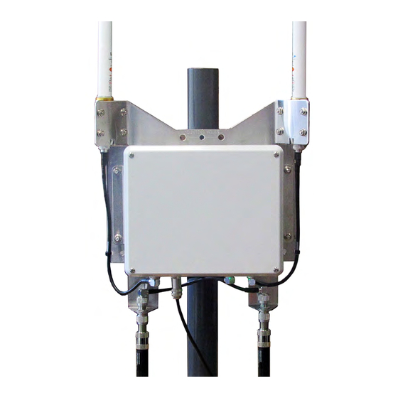
Specifications SMECIFICTRIPAS Size/Weight/Wind Loading Trea Direct Mount Antennas Height Width Depth Weight Wind Loading Area Assembly (includes network gateway 45 .5 in . 15 .5 in . 6 .5 in . 24 .3 lb 1 .7 ft transceiver enclosure, TX/RX (116 cm) (39 cm) (17 cm) - Page 5 The gateway is shipped with the TX/RX antennas and all cables attached . A packing list is shipped with the NOTE: gateway . The complete Parts List for the gateway is available in the Resource Library on the Badger Meter website, www.badgermeter.com .
-
Page 6: Tools And Materials (Customer-Supplied)
Tools and Materials (Customer-supplied) RPPLS TAD ITREOITLS (CUSRPIEO-SUMMLIED) • Phillips #2 screwdriver • Two 9/16 inch or adjustable wrenches for mounting V-block clamps (standard mounting) • BAND-IT® tool (see"Banding Mounting" on page 13) and instructions, a 1/2 inch wrench and a hammer for large diameter pole mounting •... -
Page 7: Required Pre-Installation Steps
Required Pre-Installation Steps OEQUIOED MOE-IASRTLLTRIPA SREMS Before installing the gateway, connect the battery and attach the backhaul antennas . Connect the Battery IMPORTAR The gateway contains an onboard battery backup. The battery must be connected before the gateway is installed and powered. Using a #2 slotted or Phillips screwdriver, remove the Battery connection enclosure cover by unscrewing the four corner screws . -
Page 8: Mounting The Gateway
IPUARIAG RHE GTREWTY IMPORTAR Professional installation of the ORION Fixed Network gateway transceiver per Badger Meter installation instructions is required. Installation, mounting and disposal shall be in accordance with all local, state and federal regulations. When installing the network gateway transceiver, the customer is responsible for complying with local, state and federal codes and guidelines as well as applicable industry standards, such as ANSI/TIA/EIA 222 (structural standards for steel antenna towers and antenna supporting structures) and the National Electrical Code (NEC). -
Page 9: Gateway Backplate With Brackets
Mounting the Gateway Gateway Backplate with Brackets The backplate of the gateway transceiver has a modular design consisting of four brackets joined together . The antenna brackets can be removed to provide additional mounting options . A description of each bracket starts on the next page . TX/RX Antenna Bracket TX/RX Antenna Cable Mounting Bracket... - Page 10 Mounting the Gateway Iounting Bracket The mounting bracket is machined with multiple holes to accommodate different mounting options . Mounting holes and the V-Block, banding and wall mounting options are labeled on the bracket . The bracket also has 1/4 inch and 3/8 inch grounding points (see Figure 6) which can be used if needed .
- Page 11 Mounting the Gateway Backhaul Tntenna Brackets (2) When shipped, the backhaul antenna brackets are mounted to the bottom of the mounting bracket, each with two locknuts (67810-001) . The mounting holes are shown Figure Other holes on the bracket can be used to accommodate remote installation .
-
Page 12: Using V-Block Mounting Clamps
Mounting the Gateway Using V-block Iounting Clamps The V-block mounting clamps are sized to mount the gateway on a vertical or horizontal pole with outer diameters ranging from 1-1/4… 2-1/2 inches (32…64 mm) . For mounting on poles larger than 2-1/2 inches (64 mm), see"Banding Mounting"... -
Page 13: Banding Mounting
Mounting the Gateway Place a lock washer and nut on each bolt and tighten the nuts 100…150 inch-pounds to ensure the gateway is sufficiently secured to the pole . Repeat Steps 7 and 8 for attaching the V-block clamp mounting hardware to the bottom bolts of the mounting backplate . - Page 14 Mounting the Gateway Installation of banding mounting requires the use of the BAND-IT tool shown below (66042-006) or equivalent NOTE: BAND-IT tool as recommended by BAND-IT . Figure 14: BAND-IT tool Locate the BAND-IT tool and supplied installation instructions . Follow the BAND-IT-supplied installation instructions enclosed with the BAND-IT tool for attaching the gateway transceiver to a pole .
-
Page 15: Power Source Configurations
Power Source Configurations MPWEO SPUOCE CPAFIGUOTRIPAS Tccess to Mower • The gateway transceiver requires access to power . The gateway can use a 120V AC grounded outlet for use with the AC-to-DC power supply and power cord (66528-004), or a DC power source for use with the DC power source cable with 308 in-line connector (66233-020) . -
Page 16: Lte Or Lan With 120V Ac Power Source
Power Source Configurations LRE or LTA with 120V TC Mower Source Configurations for a 120V AC grounded outlet with LTE and LAN are shown here . LRE Connection with 120V TC Mower Source ORION SE Power Cable with 308 In-line Connector (supplied) AC to DC Power Supply with 308 In-line Connector End and... - Page 17 Power Source Configurations LTA with 120V TC Mower Source Consult the manufacturer's installation and usage recommendations as well as appropriate codes, regulations and NOTE: standards for the LAN RJ45 Ethernet connection . Outdoor-rated ORION SE Power Cable with CAT5e Ethernet 308 In-line Connector Cable (customer (supplied)
- Page 18 Power Source Configurations LRE or LTA with DC Mower Source The gateway transceiver can be ordered with a 10-foot DC power source cable (66233-020) for direct connection with a customer-supplied DC power source . The gateway requires about 6W average power and 12W peak power . When connecting an AC-to-DC power supply, the recommendation is to use a power supply rated at 1A (minimum) at 24V DC .
- Page 19 Power Source Configurations LRE Connection with DC Mower Source ORION SE Power Cable with 308 In-line Connector (supplied) DC Power Source (customer supplied) 10-foot DC Power Source Cable with 308 In-line Connector End (supplied) Figure 19: LTE connection with DC power source (*Shown with NEMA 4 enclosure) LTA Connection with DC Mower Source Consult the manufacturer's installation and usage recommendations as well as appropriate codes, regulations and NOTE:...
-
Page 20: Lan With Power Over Ethernet (Poe) Power Source
Power Source Configurations LTA with Mower Pver Ethernet (MoE) Mower Source Consult the manufacturer's installation and usage recommendations as well as appropriate codes, regulations and/ NOTE: or standards for the LAN RJ45 Ethernet connection . CAT5e Outdoor-rated Ethernet Cable (customer supplied) PoE LAN RJ45 Ethernet Connection... -
Page 21: Electrical Connections
Rools and Iaterials Included with gateway: • M12 plug, 8-conductor connector (PN: 66525-002) • Badger Meter power cable, 100-foot (30 m) or 300-foot (91 m), with 308 in-line connector end • 308 in-line connector anti-tamper collar Customer-supplied: • Coax stripper (customer-supplied) •... - Page 22 Electrical Connections Strip the ends of the six (6) colored wires to a length of 1/8 inch (3 mm) . Twist the conductors on each wire . Shorten the drain/bare wire (no insulation) to 11/16 inch (17 mm) . Loosen each screw (about 2…3 turns) on the female insert and attach the wires to the female insert using the chart below .
- Page 23 Electrical Connections Remove the cap from the M12 receptacle on the bottom of the gateway transceiver . Save the cap so it can be replaced if the power cable is removed later . M12 Receptacle with Cap Removed RJ45 Receptacle Figure 25: Bottom of gateway transceiver Connect the M12 plug connector assembly to the M12 receptacle and tighten the locking ring in a clockwise direction until finger tight .
-
Page 24: Ac Power
Electrical Connections TC Mower Badger Meter provides an AC-to-DC power supply with cord (66528-004) that plugs into a standard three-prong 120V AC outlet . If you are powering the gateway directly via DC power, see "LTE or LAN with DC Power Source" on page 18 . -
Page 25: Rj45 Plug Assembly For Lan Connectivity
Electrical Connections OJ45 Mlug Tssembly for LTA Connectivity Use this procedure to connect an Ethernet cable to the gateway for a LAN backhaul or any PoE connection . Oequired Supplies: • RJ45 Plug Assembly (66527-001) as shown in Figure 29 •... - Page 26 Electrical Connections Attach the metal housing to the RJ45 receptacle on the gateway: • Remove the RJ45 receptacle RJ45 Receptacle Bayonet bayonet lock cap from the Lock Cap gateway by turning the cap 1/4 turn counter clockwise . The RJ45 receptacle cap NOTE: should be saved so it can be replaced if the Ethernet...
- Page 27 Electrical Connections Insert the Ethernet cable connector into the RJ45 receptacle (Figure 37) . Push the connector in firmly . The plug latch of the connector fits into the recessed key section of the RJ45 receptacle . A close-up view of the receptacle is shown in Figure 38 .
-
Page 28: Dual Backhaul Configuration
LAN using the RJ45 plug assembly included with the transceiver . "LAN with 120V AC Power Source" on page 17 for the LAN installation diagram . You must contact Badger Meter Technical Support to deactivate cellular backhaul service . NOTE: MOPGOTIIIAG RHE GTREWTY The gateway is programmed using a 7-pin serial programming harness (PN: 66529-002) . -
Page 29: Battery Backup Replacement
Battery Backup Replacement BTRREOY BTCKUM OEMLTCEIEAR If a battery replacement is required, complete the installation steps as detailed below in the order presented . It is not necessary to disconnect AC power from the gateway before removing the cover and replacing the battery . NOTE: Rools and Iaterials •... - Page 30 The battery contains lead and should be handled and disposed of in accordance with local, state and federal regulations . Refer to the Badger Meter Battery Handling Safety Guide, available at www.badgermeter.com . FAILURE TO PROPERLY DISPOSE OF A LEAD ACID BATTERY MAY RESULT IN BODILY HARM AND/OR PROPERTY DAMAGE FROM ACID BURNS.
-
Page 31: Remote Antenna Installation
Badger Meter specifications . Antenna cables and cable connectors are to be installed and mounted per cable and connector manufacturer instructions . -
Page 32: Assembly Size, Weight, Wind Loading
(0 .5 kg) Weatherproofing for Connector/Cable Connections Weatherproofing material should be provided by the installation contractor . Badger Meter recommends weatherproofing for all connections according to cable and connector manufacturer recommendations . Weatherproofing provides additional moisture protection and will prevent the connections from loosening due to vibrations . -
Page 33: Installation Considerations
All installation cables and devices (for example, lightning arrestor) must be included for the VSWR measurement . NOTE: Report the VSWR reading to Badger Meter for each installation using the ORION Fixed Network Gateway Installation Form. See IIMPORTAR note on document cover . -
Page 34: Required Installation Pictures
Pictures showing any other antennas in the proximity of the gateway antennas as well as potential obstructions Refer to the ORION Fixed Network Gateway Installation Form for a complete list of photos . See IIMPORTAR note on document cover . -
Page 35: Remote Antenna Installation Instructions
FCC regulations . FAILURE TO READ AND FOLLOW THE INSTRUCTIONS PROVIDED CAN LEAD TO MISAPPLICATION OR MISUSE OF THE ORION FIXED NETWORK GATEWAY TRANSCEIVER, RESULTING IN PERSONAL INJURY AND DAMAGE TO THE EQUIPMENT. Unpack the gateway assembly from the box . Locate and retain any accessories packaged with the gateway . - Page 36 Remote Antenna Installation Disconnect the enclosure bracket from the backplate by removing the two (2) locknuts from each side of the enclosure (Figure 48) . Retain the locknuts as they will be used later to reattach the enclosure bracket to the backplate . Carefully lift the enclosure (with enclosure bracket) off the backplate using caution to not damage the backhaul antenna cables .
- Page 37 11 . Collect the required VSWR readings after the antennas are installed in their final locations . Record the information on the form provided by Badger Meter . See"Required Antenna Tests" on page 33. 12 . After the antenna tests are completed, connect...
- Page 38 Figure 55: Gateway on battery backup Figure 54: Powered gateway 17 . Complete the ORION Fixed Network Gateway Installation Form and send the completed form to Badger Meter with any attachments . See IIMPORTAR note on document cover . The remote TX/RX antenna connection is complete .
- Page 39 Figure 58: Backhaul Antenna connector connector on the enclosure . Complete the ORION Fixed Network Gateway Installation Form and send the completed form to Badger Meter with any attachments . See IIMPORTAR note on document cover . The remote backhaul antenna connection is complete .
- Page 40 The Americas | Badger Meter | 4545 West Brown Deer Rd | PO Box 245036 | Milwaukee, WI 53224-9536 | 800-876-3837 | 414-355-0400 México | Badger Meter de las Americas, S.A. de C.V. | Pedro Luis Ogazón N°32 | Esq. Angelina N°24 | Colonia Guadalupe Inn | CP 01050 | México, DF | México | +52-55-5662-0882 Europe, Eastern Europe Branch Office (for Poland, Latvia, Lithuania, Estonia, Ukraine, Belarus) | Badger Meter Europe | ul.
Need help?
Do you have a question about the ORION Fixed Network and is the answer not in the manual?
Questions and answers