Table of Contents
Advertisement
MANUAL
For operation and maintenance
VERDEGRO Blade
READ BEFORE USE!
ONLY AUTHORIZED PERSONS ARE ALLOWED TO OPERATE THE MACHINE!
IMPROPER USE CAN CAUSE SERIOUS INJURIES!
All maintenance and repair should be done by the manufacturer or under
their supervision by an official distributor.
Each Blade should be delivered with original certificate to guarantee the
right performance.
US Pat. Pending No 15/043,232
Advertisement
Table of Contents

Summary of Contents for VERDEGRO Blade
- Page 1 IMPROPER USE CAN CAUSE SERIOUS INJURIES! All maintenance and repair should be done by the manufacturer or under their supervision by an official distributor. Each Blade should be delivered with original certificate to guarantee the right performance. US Pat. Pending No 15/043,232...
-
Page 2: Table Of Contents
Photos of a Blade TMA and Arrow board bracket ..........16 Cushion details extended & retracted ..............18 Blade bracket and outer dimensions ..............20 Blade with optional frame for VMS- or arrow board sign: ........21 Transport dimensions ................... 22 Operational dimensions ..................23 Typical Blade after full impact: ................ - Page 3 Cabin controller ....................44 Speed limits with mounted Blade: ............... 45 8.3.1 Truck suspension type .................. 45 8.3.2 Maximum speed table: ................. 45 Jockey wheels Operation (Optional) ..............46 8.4.1 Location jockey wheels: ................46 8.4.2 Main use jockey wheels: ................46 Supporting vehicle adjustment ..................
- Page 4 17.2 Chassis registration sticker ................... 65 CE certification ......................66 Example of a warranty request form ................67 Maintenance and repair history .................. 68 Page 4 of 68 Operation and maintenance manual Verdegro Blade...
-
Page 5: Data Producer And Specific Machine
Miami FL 33132 +1 (786)-408-5709 +1 (786)-431-3097 www.blade-tma.com sales@verdegro.com Machine number : _____________________ DLADE release date : _____________________ Company stamp: Note: This document is only valid with an original producers company stamp. Page 5 of 68 Operation and maintenance manual Verdegro Blade... -
Page 6: Introduction
The Manual for Assessing Safety Hardware (MASH) specifically addresses the performance requirements of TMA’s. The recommended tests to evaluate TMA crash performance are defined for different Test Levels. BLADE is tested according the highest test level TL-3 and is conducted at 100 kph (62 mph). -
Page 7: Keep In Mind
Keep in mind: The Blade TMA must be properly installed to a support truck. The truck including the TMA should have a minimum weight of 16.010 lbs. (7.262 kg ) and a maximum weight of 22.120 lbs. (10.033 kg ) for the best performance results. -
Page 8: Recognition And Dimensions
Recognition and dimensions 4.1 Common used terms Image Page 8 of 68 Operation and maintenance manual Verdegro Blade... - Page 9 Page 9 of 68 Operation and maintenance manual Verdegro Blade...
- Page 10 Page 10 of 68 Operation and maintenance manual Verdegro Blade...
- Page 11 Page 11 of 68 Operation and maintenance manual Verdegro Blade...
- Page 12 Page 12 of 68 Operation and maintenance manual Verdegro Blade...
- Page 13 Page 13 of 68 Operation and maintenance manual Verdegro Blade...
- Page 14 Page 14 of 68 Operation and maintenance manual Verdegro Blade...
-
Page 15: Official Blade Options
4.2 Official BLADE options Figure 1 Figure 2 Page 15 of 68 Operation and maintenance manual Verdegro Blade... -
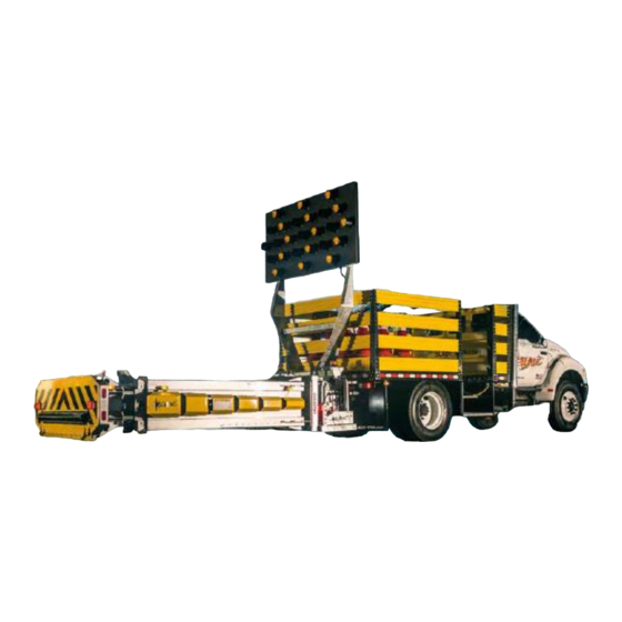
Page 16: Photos Of A Blade Tma And Arrow Board Bracket
4.3 Photos of a Blade TMA and Arrow board bracket Figure 3: Typical blade isometric view rear, cushion lowered Figure 4 Typical BLADE Attenuator truck Page 16 of 68 Operation and maintenance manual Verdegro Blade... - Page 17 Figure 5 Typical blade isometric view rear, cushion up Figure 6 Typical BLADE Attenuator truck Page 17 of 68 Operation and maintenance manual Verdegro Blade...
-
Page 18: Cushion Details Extended & Retracted
4.4 Cushion details extended & retracted Figure 7: Assembly BLADE extended cushion Page 18 of 68 Operation and maintenance manual Verdegro Blade... - Page 19 Figure 8 BLADE assembly retracted cushion Page 19 of 68 Operation and maintenance manual Verdegro Blade...
-
Page 20: Blade Bracket And Outer Dimensions
4.5 Blade bracket and outer dimensions Figure 9 Page 20 of 68 Operation and maintenance manual Verdegro Blade... -
Page 21: Blade With Optional Frame For Vms- Or Arrow Board Sign
4.6 Blade with optional frame for VMS- or arrow board sign: Figure 10 Page 21 of 68 Operation and maintenance manual Verdegro Blade... -
Page 22: Transport Dimensions
4.7 Transport dimensions Figure 11 Page 22 of 68 Operation and maintenance manual Verdegro Blade... -
Page 23: Operational Dimensions
4.8 Operational dimensions Figure 12 Page 23 of 68 Operation and maintenance manual Verdegro Blade... -
Page 24: Typical Blade After Full Impact
4.9 Typical Blade after full impact: Page 24 of 68 Operation and maintenance manual Verdegro Blade... -
Page 25: Technical Data
Battery Bank Not equipped Safety fuse hydraulics 200A Safety fuse at electric controller 12V: 50 A or 24V:25A Cable from truck to Blade Min. 2x25mm² Table 1. Dimensions and values Page 25 of 68 Operation and maintenance manual Verdegro Blade... -
Page 26: Electrical Cabinets
(four M6 bolts) and releasing the painted cover the main electric cabinet will appear. Figure 13 By removing the elastic holders it will give access to the main control cabinet (Figure 14 ). Figure 14 Page 26 of 68 Operation and maintenance manual Verdegro Blade... - Page 27 Fuses for motor control (30Amps Yellow rectangle in figure 15 ) • Optional arrow board (20Amps red rectangle in figure 15 ) • Extra sign face lights (15Amps red rectangle in figure 15 ). Figure 15 Page 27 of 68 Operation and maintenance manual Verdegro Blade...
-
Page 28: Side Guards Junction Boxes
The side guards junction boxes can be found under the fourth side guard from the main chassis. Unlock the screws holding the side guards to remove the side guards, the cover can be taken off by a screwdriver. Figure 16 Figure 17 Page 28 of 68 Operation and maintenance manual Verdegro Blade... - Page 29 The left hand side junction box (Figure 19) contains cables for: • Left hand side sensors • Left hand side extend/retract mechanism • Side markers let hand side. Figure 19 Page 29 of 68 Operation and maintenance manual Verdegro Blade...
-
Page 30: Electric Data Sheets
Connector L3 = Turn signal passenger side Connector L4 = Driving lights Connector L5 = Driving lights Connector L6 = Minus driving lights Connector L7 = Brake light Connector L8 = Reverse light Page 30 of 68 Operation and maintenance manual Verdegro Blade... -
Page 31: Junction Box Left Hand Side
5.1.2 Junction box left hand side: Figure 21 Connector 1 = Minus for driving lights driver side. Connector 2 = Plus for driving lights driver side. Page 31 of 68 Operation and maintenance manual Verdegro Blade... -
Page 32: Junction Box Right Hand Side
Connector LR = Turn signal driver side Connector LL = Turn signal passenger side Connector 1 = Minus for driving lights passenger side Connector 2 = Plus for driving lights passenger side Page 32 of 68 Operation and maintenance manual Verdegro Blade... -
Page 33: Fuse Board
Voltage Selector Fuse: F4, 2A, Fast Acting 24V Only Voltage SelectorFuse: F3, 4A, Fast Acting 12V Only Voltage Selector Fuses: Always double check before placing. Never use two fuses at once! Page 33 of 68 Operation and maintenance manual Verdegro Blade... -
Page 34: Hydraulic Data Sheet
5.3 Hydraulic Data Sheet Figure 23 Page 34 of 68 Operation and maintenance manual Verdegro Blade... -
Page 35: Warning Signs On Tma
5.4 Warning signs on TMA Note: without these stickers, it is prohibited to use BLADE! 5.4.1 Location : At the back (impact hood) Figure 24 Figure 25 Figure 26 Page 35 of 68 Operation and maintenance manual Verdegro Blade... -
Page 36: Location: On / Near The Guards Each Side Of The Tma
5.4.2 Location: On / Near the Guards each side of the TMA Figure 27 Figure 28 Page 36 of 68 Operation and maintenance manual Verdegro Blade... -
Page 37: General Specifications And Instructions
D. All Verdegro Truck Mounted Attenuators (BLADE TMA) shall be designed and manufactured by the BLADE BV, in accordance with the specifications. E. The Verdegro Blade is an attenuator system designed for installation at the back of trucks with gross vehicle weight (GVW) ranges between minimum weight of 16.010 lbs. -
Page 38: Description Of System
B. The Verdegro Blade shall have a standard LED trailer lighting system. This system shall include brake lights, taillights and turn signals. The wiring for the rear lights shall be routed and secured on the articulating frame. - Page 39 E. All welding is done by, or under the direction of a certified welder. Metal work shall only be done by Blade BV. F. All exposed steel surfaces on the Blade TMA shall be powder coated or galvanized. G. The Blade shall be assembled with original Quality bolts.
-
Page 40: Performance Criteria
4) Vehicles with a mass of 2270 kg impacting at 10 degrees into the rear of the Blade at 100 kph (62 mph) and an offset of W/4 at an angle of 10 degrees with respect to the Blade centerline, shall remain upright with the theoretical occupant impact velocity of 12 m/s or less and the occupant ride down acceleration of 20,49 g's or less per MASH, Test 3-53 evaluation criteria. -
Page 41: Safety
3. The operator of the Blade must be at least 18 years old and experienced and trained in serving Truck Mounted Attenuators. 4. The owner/holder of the Blade must ensure that all users are trained in the use of the machine, have read this manual and have taken notice on all warning signs at the machine. - Page 42 24. If you leave the Blade, put it somewhere where it does not preclude others. Keep the whole machine in transport position. Close all hatches well for unauthorized persons, turn the cabin controller off, and take your keys with you.
-
Page 43: Operation
Operation 8.1 How to use your BLADE The operation of the machine must be done using the Blade wired cabin controller. Operating the BLADE TMA is only been done using this 2 buttons shown below: Rotate down and extend the cushion: To retract and rotate the cushion up: Always Complete The Full Cycle “Up”... -
Page 44: Cabin Controller
8.2 Cabin controller Picture with short description from cabin controller; Figure 30 Page 44 of 68 Operation and maintenance manual Verdegro Blade... -
Page 45: Speed Limits With Mounted Blade
8.3.1 Truck suspension type We advise to use Trucks equipped with Air suspension. If a spring suspension truck is used; this can decrease the expected life time of the BLADE TMA and extra frequently TMA inspection will be necessary ! 8.3.2 Maximum speed table:... -
Page 46: Jockey Wheels Operation (Optional)
To raise the Jockey wheel: Rotate the handle on top of the Jockey wheel clockwise to raise its wheel. Figure 34 Never use the Jockey wheel when the TMA is extended! Forbidden to extend the Jockey wheel beyond its limit. Page 46 of 68 Operation and maintenance manual Verdegro Blade... -
Page 47: Supporting Vehicle Adjustment
The supporting vehicle, also known as an attenuator truck or impact protection vehicle, must be adjusted correct for your BLADE. It is important that the Blade is mounted correctly behind the supporting vehicle like it has been tested. Mounting the Blade to the Truck chassis can be easily done using the available TRUCK BRACKET. -
Page 48: Specifications For Truck Mounting
9.2 Specifications for truck mounting The Blade Truck bracket is full scale crash tested ( one Truck Bracket survived all required tests without necessary exchange or repair !). We require it to use this standard bracket. Other connections are available on request and have to be reviewed by Blade B.V. or it will be responsibility of the installation company. -
Page 49: Center Of Gravity
660mm from center middle hitch pin to horizontal center of the gravity point • 1035mm from center middle hitch pin to vertical center of the gravity point Figure 40 Figure 39 Page 49 of 68 Operation and maintenance manual Verdegro Blade... -
Page 50: Extended
1940mm from center middle hitch pin to horizontal center of the gravity point. • 74mm from center middle hitch pin to vertical center of the gravity point Figure 41 Figure 42 Page 50 of 68 Operation and maintenance manual Verdegro Blade... -
Page 51: Bracket Dimension
Bracket dimension The dimension from the back of truck chassis to the center of the hitch pins is 145mm horizontal. Figure 43 Page 51 of 68 Operation and maintenance manual Verdegro Blade... -
Page 52: Levelling Your Blade
10.1 Levelling your BLADE Your BLADE is delivered with a unique levelling device to adjust the horizontal position of the cushion). When the TMA is connected to the correctly installed truck bracket you can adjust the cushion position using the level device. How to do this: •... -
Page 53: Arrow Board Frame To Tma
10.2 Arrow Board Frame to TMA: We advise to install the Blade Arrow board Frame to the TMA at a vertically stored TMA (before its connected to the truck). It’s also possible to do it when TMA is already connected to the truck. -
Page 54: Post Impact Protocol
Couple off your blade by using the jacks • Wait at your BLADE until it is picked up with a crane. If you are not able to wait, set a marker on it to aware other people of the sharp edges! •... -
Page 55: Inspection
(opened and closed) Visual inspection of both racks, no damage or were out is shown Operate the Blade fully down & extend, fully retract and up, check all functions and check all led’s on cabin controller are working well... -
Page 56: Inspection Table Tma Installed To Spring Suspension Trucks
(opened and closed) Visual inspection of both racks, no damage or were out is shown Operate the Blade fully down & extend, fully retract and up, check all functions and check all led’s on cabin controller are working well... -
Page 57: Control Position Crash Cushion
12.3 Control position Crash Cushion Verify proper operation / adjustment of the cushion on a straight road surface without any height differences. After unfolding the cushion, the Blade cushion tubes and beams should be horizontal. If the machine is not leveled horizontal, directly contact the installer or manufacturer;... -
Page 58: Maintenance
Read for the maintenance of the Blade the entire manual carefully!. If in doubt about the maintenance work, it is better that it is carried out by the manufacturer. -
Page 59: Maintenance Details
ISO Nm Hex bolt Hex bolt Hex bolt Class 8.8 Class 10.9 Class 12.9 13,7 16,2 23,5 33,3 39,2 47,1 65,7 79,4 81,4 114,7 1118 1324 1863 2236 Table 5 Page 59 of 68 Operation and maintenance manual Verdegro Blade... -
Page 60: General Blade Control Points
Condition and suspension of cables o Condition of cable carrier/ chain and inside wiring o Condition of connectors o Operation of end position detectors o Installation and wiring of Gearbox motors Page 60 of 68 Operation and maintenance manual Verdegro Blade... - Page 61 Set up the entire machine as defined o Try all labor movements, which are not allowed to shock. After the test it must be properly monitored or stressed parts do not exhibit cracks or permanent deformation. Page 61 of 68 Operation and maintenance manual Verdegro Blade...
-
Page 62: Repairs (By Manufacturer Or Official Distributor)
Repairs (by manufacturer or official distributor) 15.1 Welding If parts of the Blade are repaired with welding, it should be noted in the report under "Remarks’’ and it has to be registered by certified repair body ( Certified by Blade BV ). -
Page 63: Warranty
The guarantee is effective up to 12 months from the date of delivery invoice of the machine to the consumer on all Blade TMA components and parts. The guarantee applies only to a new Blade sold in possession of the first owner, and officially delivered by Verdegro or an official distributor. -
Page 64: Documents Delivered With Your Blade
Documents delivered with your BLADE 17.1 BLADE TMA MASH certificate Figure 48 Page 64 of 68 Operation and maintenance manual Verdegro Blade... -
Page 65: Chassis Registration Sticker
17.2 Chassis registration sticker Note: Without this sticker, the Blade is not allowed to use! Sticker can be found at Left hand side on galvanized part of the TMA. Figure 49 Pictured Serial No. will be different from the delivered No. -
Page 66: Ce Certification
Machinerichtlijnen / CE- markering 2006/42/EG NEN-EN-IEC 60068-2 NEN-EN 12966-1/2/3 2002/49/EG IEC-EN 60529 NEN-12899-1 IEC-60950-1:2006 (2006/95/EG) CROW 96a/96b NEN 60068-2-47 NEN 72/245/EEG (EMC) ISO 2813 NEN-3381 NEN-EN-ISO 3506-1/2 NEN-1010 Arbo-wet NEN-EN 1050 ARAB/CODEX/AREI Page 66 of 68 Operation and maintenance manual Verdegro Blade... -
Page 67: Example Of A Warranty Request Form
Example of a warranty request form The digital warranty form can be provided by VERDEGRO GROUP. Page 67 of 68 Operation and maintenance manual Verdegro Blade... -
Page 68: Maintenance And Repair History
Stamp: Stamp: Date:……………………………………… Date:……………………………………… Blade / Truck:………………………………….. Blade / Truck:………………………………….. Remarks :……………………………………… Remarks :……………………………………… Stamp: Stamp: Date:……………………………………… Date:……………………………………… Blade / Truck:………………………………….. Blade / Truck:………………………………….. Remarks :……………………………………… Remarks :……………………………………… Stamp: Stamp: Page 68 of 68 Operation and maintenance manual Verdegro Blade...
Need help?
Do you have a question about the Blade and is the answer not in the manual?
Questions and answers