
Related Manuals for Toshiba RAV-DXC010


Summary of Contents for Toshiba RAV-DXC010
- Page 1 LC DX Interface Installation manual For commercial use Model name: RAV-DXC010 LC DX Interface ENGLISH...
-
Page 2: Table Of Contents
Please read this Installation Manual carefully before installing the LC DX interface. • This Manual describes the installation method of the LC DX interface. • You must also refer to the Installation Manual attached to the Toshiba outdoor unit. • Please follow the manual(s) for your Air Handling Unit (local supply). -
Page 3: Supplied Parts
The LC DX Interface is designed to allow the connection of a third party air handling unit (with R410A DX Coil) to a Toshiba LC outdoor unit (DI / SDI / DI-Big). The Interface consists of a LC DX Controller, including sensors (TC, TCJ and TA), and accessories that include parts which the installer needs to assemble (including brazing). -
Page 4: Installation
LC DX Interface Installation Manual INSTALLATION Use the following information to specify the appropriate AHU and DX Coil for each outdoor unit. The DX Coil design should be optimised for Cooling (Rated) Condition:- • The DX Coil must be suitable for R410A. •... - Page 5 LC DX Interface Installation Manual Design Conditions for customers DX Coil • The DX-Coil MUST be operated within the following limits to ensure reliability:- Cooling mode DX coil “air on” temp: Min: 15°CWB (18°CDB) ~ Max: 24°CWB (32°CDB) Heating mode DX coil “air on” temp: Min: 15°CDB ~ Max: 28°CDB •...
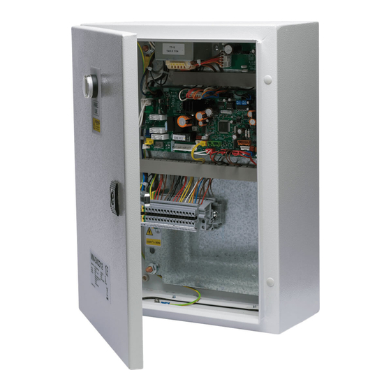
- Page 6 LC DX Interface Installation Manual LC DX INTERFACE The DX controller must not be installed outside. To avoid damage, when making holes for cables glands, please first remove the Gland Plate from the LC DX Interface. To maintain waterproof integrity IP65 glands must be used through the gland plate.
- Page 7 LC DX Interface Installation Manual DX COIL PREPARATION Sensor Holders MUST be brazed on to the DX Coil pipe work to ensure reliable temperature sensing. There are two coil sensors, these are inserted into the Sensor Holders, and secured with the sensor-fix-plate. The sensor holders should be brazed at the 6 o’clock position.
-
Page 8: Electrical Work
LC DX Interface Installation Manual ELECTRICAL WORK • Do not turn on the power of the indoor unit until WARNING vacuuming of the refrigerant pipes is completed. 1. Using the specified wires, ensure to connect Remote controller wiring the wires, and fix wires securely so that the external tension to the wires do not affect the 2-core non polarity wire is used for the remote connecting part of the terminals. - Page 9 LC DX Interface Installation Manual Remote controller wiring • 2-core with non-polarity wire is used for wiring of the remote controller wiring and group remote controllers wiring (0.75mm to 2.5mm • Strip off approx. 9mm the wire to be connected. Remote controller wiring.
- Page 10 LC DX Interface Installation Manual LC DX Interface wiring ⊗ ⊗ ⊗ ⊗ ⊗ ⊗ ⊗ ⊗ ⊗ ⊗ ⊗ ⊗ ⊗ ⊗ ⊗ ⊗ ⊗ ⊗ ⊗ ⊗ ⊗ ⊗ ⊗ ⊗ ⊗ ⊗ ⊗ ⊗ ⊗ ⊗ ⊗ ⊗...
- Page 11 LC DX Interface Installation Manual WIRING DIAGRAM...
-
Page 12: Applicable Controls
LC DX Interface Installation Manual APPLICABLE CONTROLS REQUIREMENT Changing of settings for applicable controls • When you use this air conditioner for the first time, it takes approx. 5 minutes until the remote Basic procedure for changing settings controller becomes available after power-on. This Change the settings while the air conditioner is not is normal. - Page 13 LC DX Interface Installation Manual Procedure 2 Procedure 5 Push button. When the display changes from Each time you push button, indoor unit flashing to lit, the setup is completed. numbers in the control group change cyclically. • To change settings of another indoor unit, repeat Select the indoor unit you want to change settings for.
- Page 14 LC DX Interface Installation Manual To secure better effect of Group Control heating In case of group control for system of multiple units. When it is difficult to obtain satisfactory heating One remote controller can control maximum 8 indoor units due to installation place of the indoor unit or as a group.
- Page 15 LC DX Interface Installation Manual Procedure example Indoor unit No. before setup change is displayed. Manual address setup procedure While the operation stops, change the setup. (Be sure to stop operation of the unit). Procedure 4 1. Using temp. setup buttons, specify CODE No.
- Page 16 LC DX Interface Installation Manual Procedure 6 If there is other indoor unit to be changed, repeat procedure 2 to 5 to change the setup. When the above setup has finished, push select the indoor unit No. before change of setup, specify CODE No.
- Page 17 LC DX Interface Installation Manual Remote controller switch monitoring function This function is available to call the service monitor mode from the remote controller during a test run to acquire temperatures of sensors of the remote controller, indoor unit and outdoor unit. 1.
-
Page 18: Test Run
LC DX Interface Installation Manual TEST RUN In case of wired remote controller. Before test run • Before turning on the power supply, carry out the following procedure. 1) Using 500V-Megger, check that the resistance of 1MΩ or more exists between the terminal block of the power supply and the earth (grounding). -
Page 19: Trouble Shooting
LC DX Interface Installation Manual TROUBLE SHOOTING Procedure 1 Confirmation and check When pushing buttons at the same time When a trouble occurred in the air conditioner, the for 4 seconds or more, the following display check code and the indoor unit No. appear on the appears. - Page 20 LC DX Interface Installation Manual Check codes and parts to be checked Judging Indication Main defective parts Parts to be checked / error description conditioner device status No header remote Incorrect remote controller setting --- The header remote controller has not controller been set (including two remote controllers).
- Page 21 LC DX Interface Installation Manual Judging Indication Main defective parts Parts to be checked / error description conditioner device status Outdoor unit low- Current, high-pressure switch circuit, outdoor P.C. board --- Ps pressure sensor pressure system Outdoor Entire stop error was detected or low-pressure protective operation was activated. error Duplicated header Indoor address setting error --- There are two or more header units in the...
-
Page 22: Optional Parts
LC DX Interface Installation Manual OPTIONAL PARTS ▼ Remote controllers RBC-AMT32E Wired remote controller (recommended for LC DX Interface) TCB-EXS21TLE Schedule and Weekly Timer accessory RBC-AS21E2 Simplified wired remote controller for domestic and hotel application RBC-AMS41E Wired remote controller with weekly timer RBC-AMS51E Lite-Vision plus remote controller TCB-AX32E2... -
Page 23: Declaration Of Conformity
LC DX Interface Installation Manual DECLARATION OF CONFORMITY... -
Page 24: Service Parts
LC DX Interface Installation Manual SERVICE PARTS LC DX Interface - RAV-DXC010 009, 010, 011 Location No. Part No. Description 43158187 Transformer 4316V247 Sub PCB MCC-1520-01 4316V418 Control PCB MCC-1403-05 43DX0004 KP1/KP2 Relay & Base 43DX0002 KP3 Relay (R2-230A) 43DX0003... - Page 28 Toshiba Carrier (UK) Ltd Porsham Close Belliver Industrial Estate Plymouth Devon United Kingdom PL6 7DB +44 (0) 1752 753200 +44 (0) 1752 753222 1402285701R03-EN...
Need help?
Do you have a question about the RAV-DXC010 and is the answer not in the manual?
Questions and answers