
Related Manuals for Sony WRR-850A


Summary of Contents for Sony WRR-850A
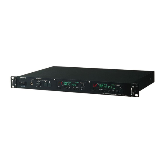
- Page 1 3-800-445-11(1) ® UHF Synthesized Diversity Tuner Operating Instructions Before operating the unit, please read this manual thoroughly and retain it for future reference. WRR-850A © 1996 by Sony Corporation...
- Page 2 Owner’s Record Notice for customers in Canada: Use of Sony wireless devices is regulated by Industry Canada as described in their The model and serial numbers are located at the Telecommunication Regulatory Circular RSS-123. rear. Record the serial number in the space A licence is normally required.
-
Page 3: Table Of Contents
Table of Contents Features ...................... 4 Channel Plan ....................5 Groups, Channels and Frequencies ............5 42 Channel System Plan ................. 9 Precautions ....................10 Location of Parts and Controls .............. 11 Front Panel ................... 11 Display....................12 Rear Panel ..................... 13 Connections .................... -
Page 4: Features
There is also a channel plan for 42 channel simultaneous operation using the 6 TV bands on UHF TV channels 64 to Twin tuners The WRR-850A has two tuner units. You can set the tuners to different channels and still operate both at the same time. Versatile display... -
Page 5: Channel Plan
125-kHz intervals in a frequency band assigned • The number of wireless microphone channels actually to a WRR-850A combination. usable in a multi-channel system may be smaller than the Note normal capacity of that system if there is interference from When using more than one channel from group 00 TV broadcasting or other RF signals. - Page 6 This group is used to simultaneously receive up to 11 In a place where an 11-channel system composed of a wireless microphone channels selected in the frequency particular WRR-850A combination is used, you cannot band assigned to a WRR-850A combination. simultaneously use another 11-channel system composed of a different WRR-850A combination.
- Page 7 This group is used to simultaneously receive up to 19 channels selected in the overall frequency band of 6 TV channels receivable by three types of tuner combinations: WRR-850A (64), WRR-850A (66) and WRR-850A (68). Frequency (in MHz) WRR-850A (64)
- Page 8 Channel Plan Group L1 (for a 7-channel system using even-numbered TV channels) This group is used to simultaniously receive up to 7 wireless microphones. Frequency (in MHz) WRR-850A (64) WRR-850A (66) WRR-850A (68) Channel Frequency Channel Frequency Channel Frequency 64-09 771.125...
-
Page 9: 42 Channel System Plan
By combining groups L1 or L2 and H1 or H2 for models 64, 66 and 68 it is possible to operate 42 channels simultaniously. When operating 42 channels simulaniously, you will need both the WD-820A and the WD- 880A antenna dividers. WRR-850A (64) WRR-850A (66) WRR-850A (68) TV Channel... -
Page 10: Precautions
Precautions • The tuner must be used within a temperature range of 0°C to +50°C (+32°F to +122°F). Avoid using the unit for extended periods at extremely high temperatures or placing it in direct sunlight, as this may damage the finish of the case. Never install the tuner on or near a heat source, such as lighting equipment or power amplifiers. -
Page 11: Location Of Parts And Controls
Location of Parts and Controls Front Panel 1 POWER switch 2 MONITOR jack 3 MONITOR LEVEL control 4 MONITOR switches and indicators 5 Display 6 FREQ +/– buttons MONITOR FREQ FREQ LEVEL POWER OUTPUT OUTPUT MUTING MUTING LEVEL LEVEL ØON øOFF UHF SYNTHESIZED DIVERSITY TUNER WRR-850 7 OUTPUT LEVEL button 8 CH button... -
Page 12: Display
Location of Parts and Controls Display 1 Number indicator 2 RF lamp 3 RF indicator 4 AF indicator 5 Battery indicator 6 Output level indicator –20 dBm –58 dBm 11 1 888. 8 888 7 GP/CH indicator 8 MUTING indicator 9 AF lamp 1 Number indicator Note... -
Page 13: Rear Panel
Rear Panel 1 ANTENNA A, B IN / DC 9 V OUT connectors 2 TUNER OUTPUT connectors 3 REMOTE connector 4 AC power output connector ⁄ AC IN DO 9V OUT DO 9V OUT ANTENNA B ANTENNA A TUNER OUTPUT REMOTE (15PIN) 5 AC IN connector 1 ANTENNA A, B IN / DC 9 V OUT (antenna A, B... -
Page 14: Connections
Connections Basic Connections AN-820A UHF antenna Antenna B Antenna A WRR-850A ⁄ AC IN DO 12V OUT DO 12V OUT ANTENNA B ANTENNA A TUNER OUTPUT REMOTE (15PIN) to AC power to input connector of a mixer, amplifier, etc. Note Make sure to use a pair of antennas. -
Page 15: Multichannel Mode
In addition to the connections below, you can combine the WRR-850A tuner with tuners WRR-820A or WRR-840A. Example of using... -
Page 16: Installation
Installation Installation of Receivers and Antennas • Small hall with a stage width of 10 meters (33 feet): Install an antenna on both sides of the stage. • Large hall with a stage width of 15 meters (50 feet) or larger: Install two antennas parallelly (1 to 2 meters [3 to 6 feet] apart) on the side of the stage closest to the sound control room. -
Page 17: Notes On Antenna Installation
Setup in halls where the sound control room is at the side of the stage Sound control room Receiver unit Antenna Notes on Antenna Installation • Use a pair of antennas. Separate them by 1 to 2 • The recommended coaxial cable for connecting the meters (3 to 6 feet). -
Page 18: System Setup
42 channels become channel. available. When using two channels When using four channels AN-820A AN-820A for four antennas WRR-850A WD-820A WRR-850A When using six channels AN-820A for four antennas When using 19 channels AN-820A... - Page 19 Example of 11-channel receiving system (using Group 11) AN-820A AN-820A Cascade connection WD-820A WD-820A WRR-850A WRR-850A Example of 8-channel receiving system (using Group 12 or 13) AN-820A AN-820A WD-820A WRR-850A...
- Page 20 Example of 13-channel receiving system (using Group A2 or A3) AN-820A AN-820A Cascade WD-820A WD-820A WRR-850A (64) WRR-850A (68) WRR-850A (66) TV Channel 64: 3 channels + TV Channel 68: 7 channels TV Channel 66: 3 channels TV Channel 64: 3 channels...
- Page 21 This setup requires both the WD-820A and the WD-880A antenna dividers. AN-820A AN-820A WD-880A TV64 TV65 TV66 WD-820A WD-820A WD-820A WRR-850A WRR-850A WRR-850A (64) (64) (66) TV Channel 64: 7 Channels TV Channel 65: 7 Channels TV Channel 66: 7 Channels Group L1 or L2...
-
Page 22: Settings
Settings You can select the reception channel and set the muting level, the reference level, etc., by following the instructions below. Selecting the Reception Channel Take the following precautions to prevent interference and noise. • Do not simultaneously use two or more microphones and transmitters that are set to the same channel. - Page 23 While holding down the GP button, press the plus (+) or minus (–) button to select a group. Pressing the plus (+) button scrolls through the groups in numerical order. (See “Groups, Channels and Frequencies” on page 5.) If “00” is displayed and you press the plus (+) button, the display returns to show “11”.
- Page 24 Settings While holding down the CH button, press the plus (+) or minus (–) button to select a channel. Similar to step 3 above, pressing the plus (+) button scrolls through the groups in the order shown in the group and reception channel list (See “Groups, Channels and Frequencies”...
-
Page 25: Setting The Muting Level
The RF lamp lights up whenever signals above 15dB µ are detected in the frequencies within the wireless channels receivable on Sony receivers. The scanning will also stop on any frequency containing a tone signal of 32.768kHz, provided the RF signal is stronger than the set muting level. - Page 26 Sony wireless microphone system. The moment a transmitter is turned on or off, it does not transmit the tone signal on the RF carrier, and this function enables the WRR-850A to squelch noise caused when a transmitter is switched on or off. It is possible to operate the WRR- 850A together with a transmitter which has no tone signal if the tone signal squelch circuit is turned off.
-
Page 27: Setting The Output Level
Setting the Output Level Press and hold down the OUTPUT LEVEL button. When you hold down this button, the tuner changes to the output level setting mode, and the output level flashes. –20 dBm –58 dBm While holding down the OUTPUT LEVEL button, press the plus (+) or minus (–) button to select the output level. -
Page 28: Operation
Operation MONITOR FREQ FREQ LEVEL POWER OUTPUT OUTPUT MUTING MUTING LEVEL LEVEL ØON øOFF UHF SYNTHESIZED DIVERSITY TUNER WRR-850 to the input connector of a mixer, amplifier, etc. UHF synthesized wireless UHF synthesized microphone transmitter Press the POWER switch. The power is turned on. Note Press the POWER switch after reducing the volume of equipment connected to the TUNER OUTPUT as noise will be heard if the power... - Page 29 For better reception The RF lamp remains on when reception is good. If the RF lamp is off, check that there are no interfering objects between the wireless microphones/transmitters and the antenna, and that they are within range of reception. •...
-
Page 30: Rack Mounting
Bottom panel WRR-850A Mount the equipment on the rack using screws that are at least 10 mm in.) long and that match the diameter of the screw holes on the rack. Rack... -
Page 31: Removing The Mounting Brackets
Removing the Mounting Brackets You can remove the rack mounting brackets from the unit if you do not intend to mount it in a rack. Dimensions Front view Rack mounting bracket WRR-850A Rack mounting bracket Side view Rack mounting bracket (Unit: mm) -
Page 32: Error Messages
The memory data is cleared. Reset the group, channel and backup memory data. muting settings. Error 02 The PLL-synthesized circuit Contact your nearest Sony dealer. has a malfunction. Error 03 The circuit has a malfunction. Contact your nearest Sony dealer. -
Page 33: Specifications
Power requirements Circuit system Dual-conversion super heterodyne 120 V AC, 60 Hz Reception frequencies Power consumption WRR-850A (64): 770.125 – 781.875 30 W + outlet 300 W max. Operating temperature WRR-850A (66): 782.125 – 793.875 0°C to +50°C (+32°F to +122°F) Storage temperature WRR-850A (68): 794.125 –... - Page 36 Sony Corporation Printed in Japan...
Need help?
Do you have a question about the WRR-850A and is the answer not in the manual?
Questions and answers