
Related Manuals for Kromschroder E8.5064 V1


Summary of Contents for Kromschroder E8.5064 V1
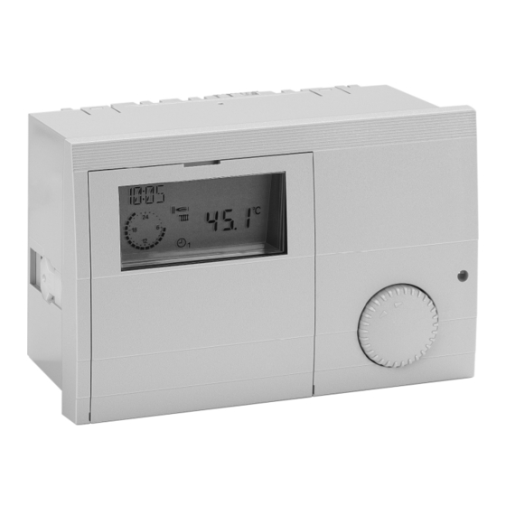
- Page 1 E8.5064 V1 System Manager Operating instructions Please observe the safety instructions and read through this manual carefully before commissioning the equipment.
-
Page 2: General Information
Safety information General information General information Description Safety information Declaration of conformity Power connection regulations Please note the connection conditions specified by your local electrical power supply company and the VDE regulations. Your heating control system may only be installed and serviced by appropriately authorised specialists. -
Page 3: Table Of Contents
Contents General information Installation Contents General information Hot water Safety information Heating circuit I / II Power connection regulations Solar/MF Warranty conditions Important text passages Note Part 2: Overview of display values and settings General area Description Date/Time/Holiday Declaration of conformity Service Function Code number Entry... - Page 4 Contents General information T-DHW L (storage tank lower temperature) ROOM INFL (Room sensor influence) T-ROOM DES A T-ROOM ADJ (room sensor adaptation) (current value for set room temperature) OPT HEAT UP (Heating optimisation) T-ROOM (room temperature) MAX OPT-TIME (Maximum bring-forward) Solar/MF OPT REDUCED (Reduction optimisation) Solar integration...
- Page 5 Contents General information HYSTERESIS HS 2 TYPE (Dyn. switching hysteresis stage 1) (secondary heat generator type HS => A7) with HYST TIME (Hysteresis time) STORAGE HS2 (heat accumulator for HS2) DETECTED HSS (number of heat generators) 37 BUFFER (heater buffer storage type) CAP/STAGE (boiler output for each stage) Screed program NEW CONFIG (new BUS configuration)
- Page 6 Contents General information Auxiliary relay functions Part 4:Appendix FUNC RELAY 1 (function selection relay MF1) 52 Remote controls T-MF1 SETP Operation-control module Merlin BM, BM 8, (switching temperature relay MF1) Lago FB MF 1 HYST (hysteresis relay MF1) Remote control FBR2 F15 FUNCTION (sensor function F15) DCF receiver Telephone switch...
- Page 7 Contents General information...
-
Page 8: Part 1: Operation
Operation in normal mode Part 1: Operation Part 1: Operation Part 1: Operation Ç Operating mode selection For initial start-up or the "level Installation" please read the installation manual. Turn the knob to select the operating mode required. The operating mode selected is indicated by a symbol at the bottom of the display. -
Page 9: Effect Of The Operating Mode
Operation in normal mode Part 1: Operation Service (automatic reset after 15 min) Boiler regulated at Boiler temperature = max. boiler temperature= see page 34 ; when the boiler temperature has reached 65°C, the consumers are regulated to their flow temperature to dissipate heat (cooling function). The cooling function must be explicitly enabled in the consumer circuits by means of a set value. -
Page 10: Display In Normal Operation
Operation in normal mode Part 1: Operation Explanations Display in normal operation Current time Freely selectable display (refer to "DISPLAY SEL" parameter) DCF reception OK (only if receiver is connected via eBUS) Bus icon (if this icon does not appear, check data line to connected CAN controllers =>... -
Page 11: Changing The Settings
Changing the settings Part 1: Operation Changing the settings Operating elements The operating flap must be opened first in order to change or request set values. Ç A => Shaft encoder => Controller switches to Operation mode Search for value/level or adjust value Ä... -
Page 12: Operating Level
Changing the settings Part 1: Operation Operating level Operation is divided into different areas: General - Display - User - Time programs – Expert - General SERVICE Expert FA. DATE/TIME/HOLIDAY Opening the hinged control panel cover automatically Open Ç Turn anticlockwise takes you to the display and indicator area. -
Page 13: Areas
Changing the settings Part 1: Operation Areas Levels General The settings in the different areas are sorted into operating levels Value selection summary • INSTALLATION Service => for service engineers • HOT WATER Date/Time/Holiday => for users • HEATING CIRCUIT I Display •... -
Page 14: Part 2: Overview Of Display Values And Settings
General area Part 2: Overview of display values and settings Part 2: Overview of display values and settings Part 2: Overview of display values and settings Ç ~ Hinged cover OPEN search for level to the left with General area Ä... - Page 15 General area Part 2: Overview of display values and settings Please do not enter the day of travel as the start Holiday => Value group date, but the first day of the holiday (no more (General -> Date/Time/Holiday level) heating from this day). All the values in this level are set in sequence =>...
-
Page 16: Service
General area Part 2: Overview of display values and settings Service Ç ~ Hinged cover OPEN search for level to the left with This area contains values for the customer service Ä open with engineers in order to provide rapid access. (Select operating level using Ç... -
Page 17: Sensor Test
General area Part 2: Overview of display values and settings SENSOR TEST Start sensor test with Ä, use Ç to select sensor => temperature is displayed; Use Ä to stop sensor test Sensor test => Value group (General -> Service level) Select sensor using Ç... -
Page 18: Sw No Xxx-Xx
General area Part 2: Overview of display values and settings SW NO XXX-XX Other entries (General -> Service level) Display software number with index (please specify if you experience problems / have questions about the controller) Select value using Ç => value is displayed CASC MANUAL (only with code no.) SW NO XXX-XX Software number with index... -
Page 19: Service
General area Part 2: Overview of display values and settings SERVICE Input of values for the yearly service message or operating hours. Delete active maintenance display: Open control panel cover, press prog. button ÄÄ, set repeat value to "00" using Ç and confirm with Ä. Delete programmed annual message: In the General/Service level, set value for SERVICE=>DAY or... -
Page 20: Display Range
Display Range Part 2: Overview of display values and settings T-OUTSIDE Display Range Display only - no adjustment possible. Display only appears if the sensor is connected and the value is The measured outside temperature is smoothed for control present in the system, otherwise "----" or no display. purposes. -
Page 21: Hot Water
Display Range Part 2: Overview of display values and settings Display only appears if the sensor is connected and Hot water the value is present in the system. T-DHW DES Current hot water set temperature If the set value is not present it is masked out, or according to heating program and hyphens appear in the display (- - - -). -
Page 22: Solar/Mf
Display Range Part 2: Overview of display values and settings This page only displays those parameters where the Solar integration corresponding functions have been implemented See the description for multifunction 1-4 under Expert. and activated. T-MF(1-4) A sensor is assigned to the four available multifunction Solar/MF relays respectively. -
Page 23: User Area
User Area Part 2: Overview of display values and settings User Area All the settings that can be made by the operator of the Ç ~ Hinged cover OPEN search for level to the right with system. Ä open with GERMAN =>... -
Page 24: Hot Water
User Area Part 2: Overview of display values and settings T-DHW 1-3 DES (Hot water temperature setting) Hot water Required hot water temperature setting Designation Value range Default T-DHW 1 DES => used in first enable time, T-DHW 2 DES => used in second enable time , 1X DHW 00, 01 (OFF/ON) 00 = OFF... -
Page 25: Heating Circuit I / Ii
User Area Part 2: Overview of display values and settings MODE Heating circuit I / II - - - - => The controller programming switch applies in this Designation Value range Default case. MODE - - - - ----, ,F1,F2, When setting an alternative operating mode this only T-ROOM DES 1*) 5°C - 40°C... -
Page 26: T-Limit Day/T-Limit N (Day/Night)
User Area Part 2: Overview of display values and settings T-LIMIT DAY/T-LIMIT N (Day/Night) Flow temperature [°C] Only valid if the function is activated => Set value "Expert/Heating circuit/PUMP MODE= 01=> Pump switching according to heating limit" If the outside temperature that is measured and calculated by the controller exceeds the heating limit specified here, heating is disabled, the pumps switch off and the mixers are closed. -
Page 27: Adaption (Heat Slope Adaptation)
User Area Part 2: Overview of display values and settings ADAPTION (Heat slope adaptation) ROOM INFL (Room sensor influence) Only active if an FBR analogue room device is connected Only active if an FBR analogue room device is connected (room sensor + operating mode selection) and an outdoor (room sensor + operating mode selection). -
Page 28: Opt Heat Up (Heating Optimisation)
User Area Part 2: Overview of display values and settings The burner is not restarted before the end of the heating OPT HEAT UP (Heating optimisation) period during the set time period (last heating time only) if Activation of function for automatically bringing forward the it not already in operation. -
Page 29: Timer Program Area
Timer Program Area Part 2: Overview of display values and settings Timer Program Area All the time programs can be set in this area. Ç ~ Hinged cover OPEN search for level to the right with Ä open with List of available time programs With maximum controller configuration Selecting a timer program Select timer program using Ç... -
Page 30: Timer/Heating Program Adjustment
Timer Program Area Part 2: Overview of display values and settings Timer/heating program adjustment Ç Select weekday (Mo-Su) or block (MO-FR => Monday-Friday, SA-SU => Saturday-Sunday, MO-SU => Monday-Sunday) Ä Open weekday/block (see left) => "I ON 20°C" First switch-on time – set value I = 20°C Ç... - Page 31 Timer Program Area Part 2: Overview of display values and settings Heat circuit 1 Heat circuit 2 Heating program 1 => factory setting: Heating program 1 => factory setting: Mo. to Fr.: 06:00 to 22.00 Mo. to Fr.: 06:00 to 22.00 Sa.
- Page 32 Timer Program Area Part 2: Overview of display values and settings Hot water Circulation Factory setting: Factory setting: Mo. to Fr.: 05:00 to 21.00 Mo. to Fr.: 05:00 to 21.00 Sa. and So.: 06:00 to 22:00 Sa. and So.: 06:00 to 22:00 Heating time 1 Heating time 2 Heating time 3 Heating time 1 Heating time 2 Heating time 3...
-
Page 33: Expert Area
Expert area Part 2: Overview of display values and settings Expert area CODE-NO These settings can only be changed if the code no. is Entering the code number (see page 16) allows all of the entered (see page 16). expert settings to be modified => including the code E If these values are set incorrectly, they may cause number itself (first parameter) malfunctions or damage to the system. -
Page 34: Ebus Supply (Supply For Ebus)
Expert area Part 2: Overview of display values and settings 00 = OFF => The resistor is not set MIN T-HS1/2 (min temperature HS) 01 = ON => The resistor is set Decreased condensation build-up in HS with low heat EBUS SUPPLY (supply for eBUS) requirements. -
Page 35: 0-10 V Function
Expert area Part 2: Overview of display values and settings 0-10 V Function Installation If the controller assigns the HS with the set temperature Designation Value range Default through a voltage input, the 0-10V output on the controller can be adjusted using the following parameters on the V-CURVE 00 - 11 voltage input of the HS. -
Page 36: T-Warm Up (Warm-Up Relief)
Expert area Part 2: Overview of display values and settings 01 = Minimum delimiter with heat requirement Installation The HS holds at least the set minimum temperature Designation Value range Default MIN T-HS. at heating requirements (Pump release). T-WARM UP 10°C - 85°C 35°C 02 = Permanent minimum delimiter (24) The HS holds 24h... -
Page 37: Detected Hss (Number Of Heat Generators)
Expert area Part 2: Overview of display values and settings DETECTED HSS (number of heat generators) Installation (only for cascades via BUS) Display of heat generators automatically reported via BUS Designation Value range Default with bus id (boiler no.) DETECTED HSS Display only CAP/STAGE (boiler output for each stage) CAP/STAGE... -
Page 38: New Config (New Bus Configuration)
Expert area Part 2: Overview of display values and settings If a boiler, which had been configured previously, is no CONTROL DEV (header control variance) longer found after a restart, or after updating the parameter Display of the header control variance CONFIG NEW, an error message is put out. -
Page 39: Reset Time (Resetting Time For I-Controller)
Expert area Part 2: Overview of display values and settings E Values set to high can lead to overheating and MAX HS-T (maximum temperature of the heat generator) triggering the STB Protects individual heat generators in the cascade from Calculation: If the cumulative system deviation in Kelvin overheating / reaches the set value A, this results in deactivation of all prevents triggering LIMITER (limiter value). -
Page 40: Modulat Dhw (Only For Hw-Boiler)
Expert area Part 2: Overview of display values and settings MODULAT DHW (only for HW-boiler) SEQU CHANGE (sequence change mode) Entry of the set modulation degree for the heat generators 01 = Only boiler sequence 1 in hot water operation (see HW-boiler). 02 = Only boiler sequence 2 03 = Change between sequence 1 and 2 according to SEQUENCE 1 (boiler sequence 1) -
Page 41: Seq Sw Time(Time To Sequence Change)
Expert area Part 2: Overview of display values and settings HYST BURNER2 (for solid fuel / 2. burner) Installation (only for cascades or two-stage operation) (only for 2-stage burners or solid fuel integration) Solid fuel integration: Hysteresis for the charging pump Designation Value range Default... -
Page 42: Switching Pattern For 2-Stage Burners
Expert area Part 2: Overview of display values and settings Switching pattern for 2-stage burners This switching patterns is also effective for operating two switching heat generators via the burner relays 57°C A6 and A7. 55°C Switch on the 1st Burner stage when temperature drops 50°C below set temperature of the heat generator. -
Page 43: Hs 1 Type (Primary Heat Generator Type)
Expert area Part 2: Overview of display values and settings 04 = 0-10V Preset Boiler set temperature Installation (configuring the installation) only for HS 1 TYPE = 01, 02 or 03 Designation Value range Default Burner relays are controlled in parallel HS 1 TYPE 00 –... -
Page 44: Buffer (Heater Buffer Storage Type)
Expert area Part 2: Overview of display values and settings 01 = Heating vis-à-vis buffer storage tank => F1, F3 Blocking HS1 HS2-T > [F3 + HYST BURNER2 + 5K] T-HS2 > HS set temperature + 5K and OFF: HS2-T < [F1 + HYST BURNER2] pump HS2 = ON 02 = Heating vis-à-vis HW tank =>... -
Page 45: Screed Program
Expert area Part 2: Overview of display values and settings Installation Screed program SCREED (activation of screed drying process) Designation Value range Default The screed program can be used for function heating in SCREED 00, 01 (OFF/ON) 00 = OFF accordance and for heating freshly laid screed ready for SCREED PROGR See explanation! -
Page 46: Hot Water
Expert area Part 2: Overview of display values and settings PARALLEL DHW (Pump parallel running) Hot water 00 => Hot water priority operation: The heating circuits are Designation Value range Default blocked during hot water preparation. The mixers close DHW RELIEF 00, 01 01 = ON and the heating circuit pumps switch off. -
Page 47: T-Hs Dhw (Increase During Hw Operation)
Expert area Part 2: Overview of display values and settings T-HS DHW (increase during HW operation) THERM INPUT (storage tank with thermostat) Boiler temperature setting with hot water preparation = 00 => Hot water preparation via storage tank sensor hot water temperature setting + T-HS DHW 01 =>... -
Page 48: Heating Circuit I / Ii
Expert area Part 2: Overview of display values and settings 02 => Swimming pool control (only for heating circuit II) The parameters in this level change in accordance with the This function can be used to heat a swimming pool. The heating circuit function that has been selected mixer controls the flow temperature for the swimming pool [HC FUNCTION]... -
Page 49: Pump Mode (Pump Operating Mode)
Expert area Part 2: Overview of display values and settings 04 => Return flow temperature increase via mixer motor ROOM INFL ="--": • The heating circuit flow sensor is used as a boiler return Flow temperature setting < 20°C. flow sensor. The mixer motor controls to the heating circuit 01 =>... -
Page 50: Mixer Close (Close Mixer Dynamic)
Expert area Part 2: Overview of display values and settings E The pump of the direct heating circuit is not switched MIXER CLOSE (close mixer dynamic) off until the boiler temperature exceeds the set Speed setting at which the mixer motor closes when a maximum flow temperature by 8K. -
Page 51: Slope Offset (Heating Slope Distance)
Expert area Part 2: Overview of display values and settings SLOPE OFFSET (heating slope distance) The boiler temperature that is required for a mixer circuit is calculated by adding the calculated temperature setting for the heating circuit flow to the heating curve distance. The heating curve distance compensates for sensor tolerances and heat loss up to the mixer. -
Page 52: Auxiliary Relay Functions
Expert area Part 2: Overview of display values and settings FUNC RELAY 1 (function selection relay MF1) Solar/MF Designation Value range Default T-MF1 SETP (switching temperature relay MF1) FUNC RELAY (1-4) 00 - 26 00,00,01,02 MF 1 HYST (hysteresis relay MF1) T-MF(1-4) SETP 30°C - 90°C 30°C... - Page 53 Expert area Part 2: Overview of display values and settings 06 = Pump HS2 22 = Solid fuel boiler integration When using the controller to control two heat generators (e.g. in connection with 2-stage HS) the relay may be used to control the pump for HS 2. T-MF1 or 1-4 = Temperature of the solid fuel boiler (Relay switches with burner relay 2;...
- Page 54 Expert area Part 2: Overview of display values and settings OFF: T-RETURN 1 > [T-MF1 SETP +MF 1 HYST] 23 = Solar integration (to MF4 because of PT1000 sensor) The return flow temperature increase pump is switched on T-SOL PANEL [T-MF4] = Temperature of the solar if the return flow temperature drops below the temperature collector setting limit (T-MF1 SETP).
-
Page 55: F15 Function (Sensor Function F15)
Expert area Part 2: Overview of display values and settings F15 FUNCTION (sensor function F15) 00 = Room sensor for heating circuit 2. If a further sensor at the pulse input [IMP] is detected at this position an FBR is evaluated. 01 = 0-10V input =>... -
Page 56: Part 3: General Function Description
Expert area Part 3: General function description Part 3: General function description Hot water generation Part 3: General function description Heat circuit control The programmed hot water temperature is stabilised by Weather-dependent control switching the hot-water cylinder charging pump and the The boiler or flow temperature is determined via the set burner. -
Page 57: Ebus Burner Controls
Expert area Part 3: General function description The function stops when the outside temperature eBUS burner controls increases to 1K above the frost protection temperature The controller supports the operation of burner controls via setting. the implemented eBUS. The unit is connected by means of the connector VII (FA eBUS). -
Page 58: Circulation Pump Control
Expert area Part 3: General function description In this case, the user should check the important settings are closed. The heating is enabled again when the outside of the controller. The warning symbol is cleared after the temperature drops below the set heating limit by 1K unit is restarted (RESET). -
Page 59: Part 4:Appendix
Remote controls Part 4:Appendix Part 4:Appendix Remote control FBR2 Remote controls Operation-control module Merlin BM, BM 8, Lago FB Connection for HC1: Connector I; (2+collective ground+3) (Only for controller models with CAN-Bus connection) Connection for HC2: Connector III; (1-3) Electrical connection: Connector IX; 1-4 The controller permits connection of an operation-control module BM for each heating circuit via a bus line. -
Page 60: Dcf Receiver
Remote controls Part 4:Appendix DCF receiver Telephone switch Electrical connection: Connector VII; Terminal 1,2 The controller can evaluate a eBUS DCF receiver on the eBUS FA-Terminals. If the DCF receiver is connected, the controller time is updated as soon as the DCF transmits a valid time on the BUS. -
Page 61: System Bus
System bus Part 4:Appendix System bus The heating system This controller can be expanded in a modular fashion using additional modules that are connected via the integrated bus. In its maximum configuration, the system can be used to control the following heating system components Boiler (modulating or switching) 1-15 Mixed weather-dependent heating circuits... -
Page 62: Error Messages
System bus Part 4:Appendix Error messages Error Error description E 78 F8: Boiler sensor / Collector sensor (cascade) E 80 Room sensor HC1, F2: F2 Buffer storage tank low Communication error sensor E 90 Adr. 0 and 1 on bus. Bus IDs 0 and 1 may not be E 83 Room sensor HC2, used simultaneously. -
Page 63: Troubleshooting
Troubleshooting Part 4:Appendix Control unit => Room temperature displayed and current Troubleshooting General room temperature setting blanked out "----" (see If your system malfunctions you should first check that the "Display/Heating circuit") controller and the control components are correctly wired. In case of communication problems Sensors: Check connecting cables: Bus lines and sensor lines must... -
Page 64: Technical Data
Technical data Technical data 230 V AC ± 10% Supply voltage to IEC 38 Burner does not switch of Power consumption Max. 8 VA at correct time Switching capacity of the relays 250 V 2(2) A Check minimum boiler Maximum current on terminal L1' 10 A temperature and type of minimum delimiter =>...
Need help?
Do you have a question about the E8.5064 V1 and is the answer not in the manual?
Questions and answers